1
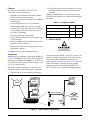
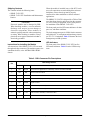
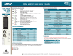
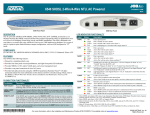
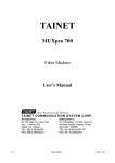
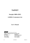
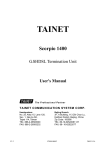
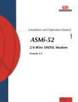
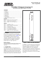
Section 61225236L1-5A
Issue 1, August 2003
T200 SHDSL T1/E1 Network Terminating Unit
Installation and Maintenance Practice
CONTENTS
1.
2.
3.
4.
5.
6.
7.
8.
General ................................................................... 1
Description ............................................................. 1
Installation .............................................................. 2
Provisioning ........................................................... 4
Operation ................................................................ 5
Maintenance ........................................................... 9
Specifications ......................................................... 9
Warranty and Customer Service ............................ 9
SHDSL
NTU
1225236L1
PWR
SHDSL
T1/E1
FIGURES
TEST
Figure 1. SHDSL T1/E1 NTU Front Panel................ 1
Figure 2. Typical System Application ....................... 2
Figure 3. SHDSL T1/E1 NTU Menu Tree................. 6
ALM
TABLES
Table 1.
Table 2.
Table 3.
Table 4.
Table 5.
Table 6.
Table 7.
Compliance Codes ...................................... 2
DB-9 Connector Pin Descriptions .............. 3
Front Panel LEDs ....................................... 4
Configuration Options List ......................... 7
E1 Port Statistics Definitions...................... 8
T1 Port Statistics Definitions...................... 9
SHDSL T1/E1 NTU Specifications............ 9
1. GENERAL
This document is an installation and maintenance
practice for the ADTRAN Total Access® SHDSL T1/
E1 Network Terminating Unit (NTU). Figure 1 illustrates the SHDSL T1/E1 NTU front panel, P/N
1225236L1.The SHDSL T1/E1 NTU is a network
terminating module using Single-Pair High Speed
Digital Subscriber Line (SHDSL) technology to
transport data over a single copper loop.
Revision History
This is the initial issue of this practice. Future changes
to this documentation will be explained in this
subsection.
2. DESCRIPTION
The SHDSL T1/E1 NTU was designed for use as a
remote unit to the Total Access 3000. The Total Access
SHDSL T1/E1 NTU provides an interface between the
SHDSL network and the customer’s Data Terminal
Equipment (DTE) for applications such as LAN to LAN
bridging, Frame Relay circuit, and PABX termination.
61225236L1-5A
V.
2
4
Figure 1. SHDSL T1/E1 NTU Front Panel
The SHDSL T1/E1 NTU is span powered with local DC
power auto-switchover. No adjustments, strapping, or
configuration changes are necessary to power the
module. The SHDSL T1/E1 NTU configuration,
testing, and performance monitoring is managed by the
VT100 local management screen menus, remotely by an
EOC terminal session, or also remotely by EOC
message protocol initiated by the Total Access SHDSL
T1/E1 LTU.
Trademarks: Any brand names and product names included in this document are
trademarks, registered trademarks, or trade names of their respective holders.
1
Features
The features of the SHDSL T1/E1 NTU, P/N
1225236L1, include the following:
• Responds to an Embedded Operations Channel
(EOC) inventory response message
• Timing source is derived from the received SHDSL
network signal
• Local management access via VT100 menus
• Remote management access via EOC message
• Operates in T1 mode with a data rate of 200 kbps
to 1.544 Mbps and E1 mode with a data rate of
192 kbps to 2.048 Mbps
• Non-volatile memory configuration
• Factory default restoration via VT100 menu screens
or EOC messages
• Firmware upgrade using local management port or
remotely via EOC messages
• Password protection for local management access
and firmware upgrade
2. This device must accept any interference received,
including interference that may cause undesired
operation.
Changes or modifications not expressly approved by
ADTRAN could void the user’s authority to operate this
equipment.
Table 1. Compliance Codes
Code
Input
Output
Power Code (PC)
F
C
Telecommunication Code (TC)
–
X
Installation Code (IC)
A
–
3. INSTALLATION
C A U T I O N !
SUBJECT TO ELECTROSTATIC DAMAGE
OR DECREASE IN RELIABILITY.
See Figure 2 for a typical configuration setup.
HANDLING PRECAUTIONS REQUIRED.
Compliance
Table 1 shows the compliance codes for the SHDSL T1/
E1 NTU. The SHDSL T1/E1 NTU is NRTL listed to the
applicable UL standards. The SHDSL T1/E1 NTU is to
be installed in a restricted access location and in a Type
“B” or “E” enclosure only.
This device complies with Part 15 of the FCC rules.
Operation is subject to the following two conditions:
After unpacking the SHDSL T1/E1 NTU, inspect it for
damage. If damage has occurred, file a claim with the
carrier, then contact ADTRAN Customer Service.
Refer to the Warranty and Customer Service section for
further information. If possible, keep the original
shipping container for returning the SHDSL T1/E1
NTU for repair or for verification of shipping damage.
1. This device may not cause harmful interference.
VT100
Management
System
Network
VT100
2-Wire Twisted Pair
LTU
1181308L1
PWR
1
2
3
SHDSL
NTU
1225236L1
PWR
SHDSL
P
O
R
T
T1/E1
TEST
ALM
4
OPT
SCU
LTU
1181018L1
1181308L1
PWR
LTU
1181308L1
PWR
1
SELECT
ALM
2
3
LTU
LTU
1181308L1
PWR
1
P
O
R
T
2
3
MODE
FSE
1181308L1
PWR
1
P
O
R
T
2
3
2
3
LTU
LTU
1181308L1
PWR
1
P
O
R
T
1181308L1
PWR
1
P
O
R
T
2
3
2
3
LTU
LTU
1181308L1
PWR
1
P
O
R
T
1181308L1
PWR
1
P
O
R
T
2
3
2
3
LTU
LTU
1181308L1
PWR
1
P
O
R
T
1181308L1
PWR
1
P
O
R
T
2
3
2
3
LTU
LTU
1181308L1
PWR
1
P
O
R
T
1181308L1
PWR
1
P
O
R
T
2
3
2
3
LTU
LTU
1181308L1
PWR
1
P
O
R
T
1181308L1
PWR
1
P
O
R
T
2
3
2
3
LTU
LTU
1181308L1
PWR
1
P
O
R
T
1181308L1
PWR
1
P
O
R
T
2
3
2
3
LTU
LTU
1181308L1
PWR
1
P
O
R
T
1181308L1
PWR
1
P
O
R
T
2
3
2
3
LTU
LTU
1181308L1
PWR
1
P
O
R
T
1181308L1
PWR
1
P
O
R
T
2
3
2
3
LTU
LTU
1181308L1
PWR
1
P
O
R
T
1181308L1
PWR
1
P
O
R
T
2
3
2
3
LTU
LTU
1181308L1
PWR
1
P
O
R
T
1181308L1
PWR
1
P
O
R
T
2
3
2
3
LTU
LTU
1181308L1
PWR
1
P
O
R
T
1181308L1
PWR
1
P
O
R
T
2
3
LTU
LTU
1181308L1
PWR
1
P
O
R
T
2
3
1181308L1
PWR
1
P
O
R
T
2
3
1
P
O
R
T
2
3
4
4
4
4
4
4
4
4
4
4
4
4
4
4
4
4
4
4
4
4
4
4
4
4
4
4
4
4
OPT
OPT
OPT
OPT
OPT
OPT
OPT
OPT
OPT
OPT
OPT
OPT
OPT
OPT
OPT
OPT
OPT
OPT
OPT
OPT
OPT
OPT
OPT
OPT
OPT
OPT
OPT
OPT
HST
ACO
ACO
C
R
A
F
T
SCU
A
B
1
2
3
4
5
6
7
8
9
10
11
12
13
14
15
16
17
18
19
20
21
22
23
24
Total Access 3000
25
26
27
28
P
O
R
T
SHDSL
T1/E1
LTU
SHDSL
T1/E1
NTU
Customer T1 or E1
Equipment
(e.g., PABX)
Figure 2. Typical System Application
2
Issue 1, August 2003
61225236L1-5A
Shipping Contents
The contents include the following items:
• SHDSL T1/E1 NTU
• SHDSL T1/E1 NTU Installation and Maintenance
Practice
CAUTION
Electronic modules can be damaged by ESD.
When handling modules, wear an antistatic
discharge wrist strap to prevent damage to
electronic components. Place modules in
antistatic packing material when transporting
or storing. When working on modules, always
place them on an approved antistatic mat that is
electrically grounded.
When the module is installed in any of the NTU enclosures, all connections are made through the enclosure
backplanes. Ensure chassis ground is properly
connected for either standalone or chassis-mounted
applications.
The SHDSL T1/E1 NTU is designed for a T200 or T400
type form factor housing and inserts into the customer
T1 or E1 T200 type equipment. Follow local practice
for installation of the SHDSL T1/E1 NTU.
The front panel provides LED status indicators for data
port, test, and alarm conditions.
The local management port is a DB-9 female connector
and is labeled V.24, with pinout and interchange circuits
per ITU-T V.24 standards. Table 2 illustrates the local
management port DB-9 pinouts.
Instructions for Installing the Module
All connections of the SHDSL T1/E1 NTU are made
through card edge connectors. The module operates in a
standalone chassis, or the ADTRAN HR12 HDSL
chassis.
LED Indicators
The front panel of the SHDSL T1/E1 NTU has five
LED status indicators. Table 3 lists the LED descriptions.
Table 2. DB-9 Connector Pin Descriptions
Pin
Interchange Circuit
No.
Name
Function
1
109
RLSD
2
104
RD
Receive Data from DCE
3
103
TD
Transmit Data to DCE
4
108/2
DTR
5
102
SGND
6
107
DSR
Data Set Ready - Internally connected to RLSD and DTR
7
105
RTS
Ready to Send - Internally connected to CTS
8
106
CTS
Clear to Send - Internally connected to RTS
9
---
NC
Not Connected
61225236L1-5A
Received Line Signal Detect - Internally connected to DTR and DSR
Data Terminal Ready - Internally connected to RLSD and DSR
Signal Ground
Issue 1, August 2003
3
Table 3. Front Panel LEDs
LED
Indication
Description
PWR
Off
Green
The module is powered off
The module is In Service
SHDSL
Green
Yellow
Red
T1/E1
Off
Green
TEST
Off
Green
Yellow
Red
Module is not in loopback or BERT
Local loopback is active or BERT is running with no errors
BERT is running with bit errors
BERT is running with no pattern sync
ALM
Off
Yellow
Red
No alarm condition detected
Alarm condition detected remotely
Alarm condition detected locally
SHDSL loop is trained with good signal quality
SHDSL loop is trained with poor signal quality
SHDSL loop is not trained
Port is active with alarms
Port is active with no alarms
4. PROVISIONING
The SHDSL T1/E1 NTU menus are accessed via the
DB-9 front panel female connector which supports
VT100 emulation by PC based application programs or
by a virtual terminal session over the EOC.
The parameters of the VT100 terminal should be set as
follows:
•
•
•
•
•
NOTE
9600 Baud
No parity
8 Data bits
1 Stop bits
No Flow Control
To ensure proper display background, select
VT100 terminal emulation under Settings.
Once these steps have been completed, the following
options will appear in the SHDSL T1/E1 NTU Main
Menu:
1.
2.
3.
4.
5.
4
Unit Information
Provisioning
Status
Test
Performance History
Windows HyperTerminal
Windows HyperTerminal can be used as a VT100
terminal emulation program. Open HyperTerminal by
selecting Programs/Accessories/HyperTerminal. Refer
to the Help section of HyperTerminal for additional
information.
The menu tree in Figure 3 illustrates the path to every
provisioning, performance, and test access point in the
SHDSL T1/E1 menu system.
Table 4 lists the complete set of configurable options
with settings and factory default values.
NOTE
When the NTU is in T1 mode, all related E1
options will be non-applicable. A non-applicable option setting is still changeable, but will
not take affect until the option become applicable.
Issue 1, August 2003
61225236L1-5A
5. OPERATION
Test Capabilities
The SHDSL T1/E1 NTU has the following test capabilities:
•
•
•
•
•
Self diagnostics
Local loopbacks
EOC initiated remote loopbacks
Inband remote loopback detection (E1 mode only)
Internal bit error rate tester (BERT)
Self Diagnostics
The SHDSL T1/E1 NTU performs self diagnostic tests
of its Read Only Memory (ROM), Random Access
Memory (RAM), LEDs, and non-volatile configuration
setting upon power-up.
Local and Remote Loopbacks
For troubleshooting purposes, the SHDSL T1/E1 NTU
provides three types of loopback tests.
1. Dual sided
2. Network
3. Customer
Inband Loopback Detection
Inband remote loopback response is supported on the
E1 port. The SHDSL T1/E1 NTU supports V.54 and
PN127 inband signalling protocols.
BERT
The SHDSL T1/E1 NTU contains a built-in Bit Error
Rate Test (BERT). The BERT involves injecting and
detecting a Pseudorandom Binary Sequence (PRBS)
toward the network on the selected payload (i.e. G.703
or entire SHDSL payload). The PRBS used in the
SHDSL T1/E1 NTU is PRS15 as defined in ITU-T
0.150 and 0.151. It is also known as 2e15 – 1 pattern.
61225236L1-5A
Customer Port
The SHDSL T1/E1 NTU operates in either E1 mode or
T1 mode.
E1 Mode
In E1 mode the port features are as follows:
• Carries information at the rate of 2.048 Mbps
• Uses CCS framed format with or without CRC-4
• Operates in either Alternate Mark Inversion (AMI)
or High-Density Bipolar 3 (HDB3) line code
• Provides programmable timeslot idle pattern
• Supports ISDN-PRA V3 service
• Displays additional status information via a local
VT100 management screen
See Table 5 for E1 port statistics definitions.
T1 Mode
In T1 mode the port features are as follows:
• Carries information at the rate of 1.544 Mbps
• Uses Superframe Format (SF) or Extended Superframe Format (ESF)
• Operates in either Alternate Mark Inversion (AMI)
or Bipolar w/8-Zero Substitution (B8ZS) line code
• Provides programmable timeslot idle pattern
• Monitors the Facility Data Link (FDL) for loopback
commands
• Displays additional status information via a local
VT100 management screen
See Table 6 for T1 port statistics definitions.
Issue 1, August 2003
5
6
PRELIMINARY
Main
Menu
SHDSL Version
Vendor List Number
Vendor Issue Number
Vendor Software Version
Unit Identification Code (CLEI)
Vendor ID
Vendor Model Number
Vendor Serial Number
Other Vendor Information
1. LTU
1. Unit Information
2. NTU
1. Unit Options
1. Data Mode = T1/E1, Timeslots
2. Local Management = Enabled
3. Restore Factory Defaults
4. Upgrade Firmware
1. Disabled
1. Data Type = E1
2. Data Rate = 3
2. Enabled
3. Apply Settings
5. Change Password
1. SES Count Threshold = 50 CVCs
1.-255. CVCs to cause a SES
0. Disabled
2. SNR Margin Alarm Threshold = Disabled
2. Provisioning
2. SHDSL Options
1-15. Threshold in dB
0. Disabled
3. Loop Attenuation Alarm Threshold = Disabled
1-127. Threshold in dB
0. Disabled
4. ES 15 Minute Alarm Threshold = Disabled
1-900. Seconds
5. SES 15 Minute Alarm Threshold = Disabled
1. Line Coding = HDB3*
6. UAS 15 Minute Alarm Threshold = Disabled
Issue 1, August 2003
7. CVC 15 Minute Alarm Threshold = Disabled
8. LOSWS 15 Minute Alarm Threshold = Disabled
3.
2. T1 Options
2. Line Coding*
1-65535. Errors
1. 0 db
2. -7.5 db
3. -15 db
3. ISDN-PRA V3 = Disabled*
2. B8ZS
4. Idle Pattern*
5. FDL Monitoring*
4. Test Options
1. Disabled
2. SF
3. ESF
2. BERT Pattern = 2e15-1
4. Test
61225236L1-5A
1. SHDSL
2. E1
0. Disabled
1-999. Timeout in Minutes
1. Loopback Time Out = Disabled
1. SHDSL = ALARMS
2. E1 = ALARMS
1. Local Loopback
2. Remote Loopback
3. BERT
5. Performance History
1. Unframed
2. Enabled
3. BERT Pattern Polarity = Normal
1. AMI
2. HDB3
1. Disabled
1. Unframed
2. CCS
3. CCS w/CRCA
2. Enabled
4. Idle Pattern = FFh*
1. AMI
3. Framing Mode*
6. Terminal Mode
0. Disabled
2. Framing Mode = CCS*
1. E1 Options
1. DS1 Tx Level
3. Status
SHDSL Version
Vendor List Number
Vendor Issue Number
Vendor Software Version
Unit Identification Code (CLEI)
Vendor ID
Vendor Model Number
Vendor Serial Number
Manufacture Date
PROM Check Sum
1. Normal
2. Inverted
1. ALT
2. 2047
3. 2e15-1
4. QRSS
1. Dual Sided
2. Customer
3. Network
4. Off
* Option must be changed by the LTU
Figure 3. SHDSL T1/E1 NTU Menu Tree
General Status
Aggregate Rate (kbps)
SNR Margin (dB) (Cur/Min/Max)
Loop Attenuation (dB) (Cur/Min/Max)
Errored Seconds (ES)
Severely Errored Seconds (SES)
Unavailable Seconds (UAS)
Code Violations Count (CVC)
LOSW Seconds (LOSWS)
Loopback Status
BERT Status
General Status
Data Rate
Framing Mode
Errored Seconds (ES)
Severely Errored Seconds (SES)
Unavailable Seconds (UAS)
Code Violations Count (CVC)
Transmit Network Alarm Indication Signal (Tx Net AIS)
Transmit Customer Alarm Indication Signal (Tx Cust AIS)
Network Source Address Bits (Net SAS-Bits)
Customer Source Address Bits (Cust SA -Bits)
Network Address Bit (Cust A-Bit)
Table 4. Configuration Options List
Category
Unit Options
Option
Setting
Default
For Data Type = T1, Data Rate can
be from 3 to 24 time slots
(i.e. 200 kbps to 1.544 Mbps)
Data Type = T1
For Data Type = E1, Data Rate can
be from 3 to 32 time slots
(i.e., 192 kbps to 2.048 Mbps)
Data Rate = 24
1 = Disabled
2 = Enabled
Enabled
SES CVC Threshold
0 to 255 CVC’s
50
SNR Margin Alarm
Threshold
0 = Disabled
1 to 15db = Alarm Threshold
Disabled
Loop Attenuation Alarm
Threshold
0 = Disabled
1 to 127db = Alarm Threshold
Disabled
ES 15 Minute Alarm
Threshold
0 = Disabled
1 to 900 Seconds = Alarm Threshold
Disabled
SES 15 Minute Alarm
Threshold
0 = Disabled
1 to 900 Seconds = Alarm Threshold
Disabled
UAS 15 Minute Alarm
Threshold
0 = Disabled
1 to 900 Seconds = Alarm Threshold
Disabled
CVC 15 Minute Alarm
Threshold
0 = Disabled
1 to 65535 Errors = Alarm threshold
Disabled
LOSWS 15 Minute Alarm
Threshold
0 = Disabled
1 to 900 Seconds = Alarm Threshold
Disabled
Line Coding
1 = AMI
2 = B8ZS
B8ZS
Framing Mode
1 = Unframed
2 = SF
3 = ESF
ESF
Idle Pattern
00h to FFh
7Fh
FDL Monitoring (ESF Mode
Only)
1 = Disabled
2 = Enabled
Disabled
Data Mode
Local Management
Restore Factory Defaults
Firmware Upgrade
Change Password
SHDSL Options
T1 Options (T1 Mode Only)
61225236L1-5A
Issue 1, August 2003
7
Table 4. Configuration Options List (Continued)
Category
E1 Options (E1 Mode Only)
Test options
Option
Setting
Default
Line Coding
1 = AMI
2 = HDB3
HDB3
Framing Mode
1 = Unframed
2 = CCS
3 = CCS w/CRC-4
CCS
Idle Pattern
00h to FFh
FFh
ISDN - PRA V3 (CCS or
CCS w/CRC-4 Mode Only)
1 = Disabled
2 = Enabled
Disabled
Loopback Timeout
0 = Disabled
1 to 999 Minutes = Timeout
Disabled
BERT Pattern
1 = ALT
2 + 2047
3 = 2e15 – 1
4 = QRSS
2e15 – 1
BERT Pattern Polarity
1 = Normal
2 = Inverted
Normal
Inband Loopback Protocol
1 = PN127
PN127
2 = V.54
Inband Loopback Detection
Disabled
1 = Disabled
2 = Enabled
Table 5. E1 Port Statistics Definitions
Statistic
Errored Seconds (ES)
Definition
Unframed
LOS condition or BPV’s > 0
CCS
LOS or LOF condition, or if BPV’s > or FE’s > 0
CCS w/CRC-4
LOS, LOF, or LOMFA condition, or if FE’s > 0 or CRC-4
errors > 0
Unframed
LOS condition
CCS
LOS or LOF condition or if FE’s > 4
CCS w/CRC-4
LOS, LOF, or LOMFA condition, or if FE’s > 4 or CRC-4
errors ≥ 300
Unavailable Seconds (UAS)
N/A
If 10 continuous SES’s, then UAS
If 10 continuous seconds with no SES’s, then no UAS
Code Violations Count (CVC)
Unframed
If BPV’s > 0
CCS
If BPV’s > 0, or FE’s > 0
CCS w/CRC-4
If FE’s > 0 or CRC-4 errors > 0
Severely Errored Seconds (SES)
8
Framing Mode
Issue 1, August 2003
61225236L1-5A
Table 6. T1 Port Statistics Definitions
Statistic
Errored Seconds (ES)
Framing Mode
Definition
Unframed
LOS condition or BPV’s > 0
SF
LOS or LOF condition, or if BPV’s > 0 or FE’s > 0
ESF
LOS or LOF condition, or if BPV’s > 0 or FE’s > 0
Unframed
LOS condition or BPV’s > 1544
SF
LOS or LOF condition, or if BPV’s > 1544 or if FE’s > 8
ESF
LOS or LOF condition, or if BPV’s > 1544 or if FE’s > 8
Unavailable Seconds (UAS)
N/A
If 10 continuous SES’s, then UAS
If 10 continuous seconds with no SES’s, then no UAS
Code Violations Count (CVC)
Unframed
If BPV’s > 0
SF
If BPV’s > 0 or FE’s > 0
ESF
If BPV’s > 0 or FE’s > 0
Severely Errored Seconds (SES)
6. MAINTENANCE
The SHDSL T1/E1 NTU requires no routine maintenance for normal operation.
Table 7. SHDSL T1/E1 NTU Specifications
Environmental
ADTRAN does not recommend that repairs be
attempted in the field. Repair services may be obtained
by returning the defective unit to ADTRAN. Refer to
the Warranty and Customer Service section for further
information.
Operating Temperature:
7. SPECIFICATIONS
Specifications for the SHDSL T1/E1 NTU are detailed
in Table 7.
Maximum Current Draw:
Storage Temperature:
Relative Humidity:
8. WARRANTY AND CUSTOMER SERVICE
ADTRAN will replace or repair this product within the
warranty period if it does not meet its published specifications or fails while in service. Warranty information
can be found at www.adtran.com/warranty.
Maximum Heat
Dissipation:
–0°C to 55°C
–40°C to 85°C
90 percent maximum @
50°C, noncondensing
0.074 A maximum
@ Ð48 VDC
3.55 watts
Physical
Dimensions:
Weight:
5.625 in. H x .625 in. W x
6.0 in. D
< 1 lb.
Part Number
SHDSL T1/E1 NTU
Module:
61225236L1-5A
Issue 1, August 2003
1225236L1
9
10
Issue 1, August 2003
61225236L1-5A