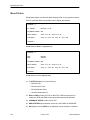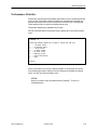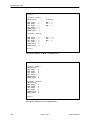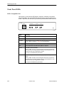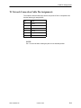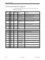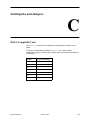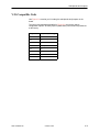
1
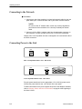
HOTWIRE
MODEL 7924 STANDALONE
T1 HDSL TERMINATION UNIT
USER’S GUIDE
Document No. 7924-A2-GB20-30
October 1997
Copyright 1997 Paradyne Corporation.
All rights reserved.
Printed in U.S.A.
Notice
This publication is protected by federal copyright law. No part of this publication may be copied or distributed,
transmitted, transcribed, stored in a retrieval system, or translated into any human or computer language in any form
or by any means, electronic, mechanical, magnetic, manual or otherwise, or disclosed to third parties without the
express written permission of Paradyne Corporation, 8545 126th Avenue North, P.O. Box 2826, Largo,
Florida 33779-2826.
Paradyne Corporation makes no representation or warranties with respect to the contents hereof and specifically
disclaims any implied warranties of merchantability or fitness for a particular purpose. Further, Paradyne Corporation
reserves the right to revise this publication and to make changes from time to time in the contents hereof without
obligation of Paradyne Corporation to notify any person of such revision or changes.
Changes and enhancements to the product and to the information herein will be documented and issued as a new
release to this manual.
Trademarks
All products and services mentioned herein are the trademarks, service marks, registered trademarks or registered
service marks of their respective owners.
Warranty, Sales, and Service Information
Contact your sales or service representative directly for any help needed. For additional information concerning
warranty, service, repair, spare parts, installation, documentation, or training, use one of the following methods:
Via the Internet: Visit the Paradyne World Wide Web site at http://www.paradyne.com
Via Telephone: Call our automated call system to receive current information via fax or to speak with a
company representative.
— Within the U.S.A., call 1-800-870-2221
— International, call 727-530-2340
Printed on recycled paper
A
October 1997
7924-A2-GB20-30
Important Information
Important Safety Instructions
1. Read and follow all warning notices and instructions marked on the product or included in the manual.
2. Do not allow anything to rest on the power cord and do not locate the product where persons will walk on the
power cord.
3. Do not attempt to service this product yourself, as opening or removing covers may expose you to dangerous
high voltage points or other risks. Refer all servicing to qualified service personnel.
4. General purpose cables are provided with this product. Special cables, which may be required by the regulatory
inspection authority for the installation site, are the responsibility of the customer.
5. When installed in the final configuration, the product must comply with the applicable Safety Standards and
regulatory requirements of the country in which it is installed. If necessary, consult with the appropriate regulatory
agencies and inspection authorities to ensure compliance.
6. A rare phenomenon can create a voltage potential between the earth grounds of two or more buildings. If
products installed in separate buildings are interconnected, the voltage potential may cause a hazardous
condition. Consult a qualified electrical consultant to determine whether or not this phenomenon exists and, if
necessary, implement corrective action prior to interconnecting the products.
7. In addition, if the equipment is to be used with telecommunications circuits, take the following precautions:
— Never install telephone wiring during a lightning storm.
— Never install telephone jacks in wet locations unless the jack is specifically designed for wet locations.
— Never touch uninsulated telephone wires or terminals unless the telephone line has been disconnected at the
network interface.
— Use caution when installing or modifying telephone lines.
— Avoid using a telephone (other than a cordless type) during an electrical storm. There may be a remote risk of
electric shock from lightning.
— Do not use the telephone to report a gas leak in the vicinity of the leak.
7924-A2-GB20-30
October 1997
B
Important Information
EMI Warnings
! WARNING:
This equipment has been tested and found to comply with the limits for a Class A digital device,
pursuant to Part 15 of the FCC rules. These limits are designed to provide reasonable protection against
harmful interference when the equipment is operated in a commercial environment. This equipment
generates, uses, and can radiate radio frequency energy and, if not installed and used in accordance
with the instruction manual, may cause harmful interference to radio communications. Operation of this
equipment in a residential area is likely to cause harmful interference in which case the user will be
required to correct the interference at his own expense.
The authority to operate this equipment is conditioned by the requirements that no modifications will be
made to the equipment unless the changes or modifications are expressly approved by Paradyne
Corporation.
! WARNING:
To Users of Digital Apparatus in Canada:
This Class A digital apparatus meets all requirements of the Canadian interference-causing equipment
regulations.
Cet appareil numérique de la classe A respecte toutes les exigences du règlement sur le matérial
brouilleur du Canada.
C
October 1997
7924-A2-GB20-30
Contents
About This Guide
Document Purpose and Intended Audience . . . . . . . . . . . . . . . . . . . . . . . . . v
Document Summary . . . . . . . . . . . . . . . . . . . . . . . . . . . . . . . . . . . . . . . . . . . . . v
Product-Related Documents . . . . . . . . . . . . . . . . . . . . . . . . . . . . . . . . . . . . . . vi
1
About HotWire Model 7924 Termination Units
HotWire 7924-A1 Models and Features . . . . . . . . . . . . . . . . . . . . . . . . . . . . 1-1
Typical Configurations . . . . . . . . . . . . . . . . . . . . . . . . . . . . . . . . . . . . . . . . . . . 1-3
User Interface Types . . . . . . . . . . . . . . . . . . . . . . . . . . . . . . . . . . . . . . . . . . . . 1-5
2
Installing the Unit
Overview . . . . . . . . . . . . . . . . . . . . . . . . . . . . . . . . . . . . . . . . . . . . . . . . . . . . . . 2-1
Package Checklist for HotWire Model 7924-A1 . . . . . . . . . . . . . . . . . . . . . . 2-1
Connecting to the Network . . . . . . . . . . . . . . . . . . . . . . . . . . . . . . . . . . . . . . . 2-2
Connecting Power to the Unit . . . . . . . . . . . . . . . . . . . . . . . . . . . . . . . . . . . . . 2-2
3
Using Terminal and Switchpack Modes
Choosing an Interface Mode . . . . . . . . . . . . . . . . . . . . . . . . . . . . . . . . . . . . . . 3-1
Connecting to a System Terminal . . . . . . . . . . . . . . . . . . . . . . . . . . . . . . . . . 3-1
Switching Between Terminal and Switchpack Modes . . . . . . . . . . . . . . . . . 3-2
4
Customizing DSX-1-Compatible Units
Accessing Configuration Options . . . . . . . . . . . . . . . . . . . . . . . . . . . . . . . . . . 4-1
Making Changes from the Terminal Interface . . . . . . . . . . . . . . . . . . . . . . . 4-2
Making Changes in Switchpack Mode . . . . . . . . . . . . . . . . . . . . . . . . . . . . . 4-5
Displaying Switchpack Definitions . . . . . . . . . . . . . . . . . . . . . . . . . . . . . 4-5
Displaying Line Build-Out Definitions . . . . . . . . . . . . . . . . . . . . . . . . . . . 4-6
7924-A2-GB20-30
October 1997
i
Contents
5
Customizing V.35-Compatible Units
Accessing Configuration Options . . . . . . . . . . . . . . . . . . . . . . . . . . . . . . . . . . 5-1
Making Changes from the Terminal Interface . . . . . . . . . . . . . . . . . . . . . . . 5-2
Making Changes in Switchpack Mode . . . . . . . . . . . . . . . . . . . . . . . . . . . . . 5-4
Displaying Switchpack Definitions . . . . . . . . . . . . . . . . . . . . . . . . . . . . . 5-5
6
Monitoring the Unit
What to Monitor . . . . . . . . . . . . . . . . . . . . . . . . . . . . . . . . . . . . . . . . . . . . . . . . . 6-1
Board Status . . . . . . . . . . . . . . . . . . . . . . . . . . . . . . . . . . . . . . . . . . . . . . . . . . . 6-2
Performance Statistics . . . . . . . . . . . . . . . . . . . . . . . . . . . . . . . . . . . . . . . . . . . 6-3
Remote Unit Information . . . . . . . . . . . . . . . . . . . . . . . . . . . . . . . . . . . . . . . . . 6-5
Front Panel LEDs . . . . . . . . . . . . . . . . . . . . . . . . . . . . . . . . . . . . . . . . . . . . . . . 6-6
DSX-1-Compatible Unit . . . . . . . . . . . . . . . . . . . . . . . . . . . . . . . . . . . . . . 6-6
V.35-Compatible Unit . . . . . . . . . . . . . . . . . . . . . . . . . . . . . . . . . . . . . . . . 6-7
7
Testing
Detecting a Problem . . . . . . . . . . . . . . . . . . . . . . . . . . . . . . . . . . . . . . . . . . . . . 7-1
Understanding Loopback Tests . . . . . . . . . . . . . . . . . . . . . . . . . . . . . . . . . . . 7-1
Local Loopbacks . . . . . . . . . . . . . . . . . . . . . . . . . . . . . . . . . . . . . . . . . . . . 7-2
Remote Loopbacks . . . . . . . . . . . . . . . . . . . . . . . . . . . . . . . . . . . . . . . . . . 7-3
Starting and Stopping Loopbacks . . . . . . . . . . . . . . . . . . . . . . . . . . . . . . 7-4
Resetting the Unit . . . . . . . . . . . . . . . . . . . . . . . . . . . . . . . . . . . . . . . . . . . . . . . 7-5
A
Worksheets
Overview . . . . . . . . . . . . . . . . . . . . . . . . . . . . . . . . . . . . . . . . . . . . . . . . . . . . . . A-1
DSX-1-to-DSX-1 Configuration . . . . . . . . . . . . . . . . . . . . . . . . . . . . . . . . . . . . A-2
DSX-1-to-V.35 Configuration . . . . . . . . . . . . . . . . . . . . . . . . . . . . . . . . . . . . . A-3
Unframed Operation . . . . . . . . . . . . . . . . . . . . . . . . . . . . . . . . . . . . . . . . . A-4
Time Slot (DS0) Assignments . . . . . . . . . . . . . . . . . . . . . . . . . . . . . . . . . A-4
DSX-1-Compatible Units Configuration Worksheet . . . . . . . . . . . . . . . . . . A-5
V.35-Compatible Units Configuration Worksheet . . . . . . . . . . . . . . . . . . . . A-5
ii
October 1997
7924-A2-GB20-30
Contents
B
Cable Pin Assignments
Terminal Connection Cable Pin Assignments . . . . . . . . . . . . . . . . . . . . . . . B-1
HDSL Loop Connection Cable Pin Assignments . . . . . . . . . . . . . . . . . . . . . B-2
T1 Network Connection Cable Pin Assignments . . . . . . . . . . . . . . . . . . . . . B-3
V.35 Connection Cable Pin Assignments . . . . . . . . . . . . . . . . . . . . . . . . . . . B-4
C
Switchpacks and Jumpers
DSX-1-Compatible Units
. . . . . . . . . . . . . . . . . . . . . . . . . . . . . . . . . . . . . . . . C-1
V.35-Compatible Units . . . . . . . . . . . . . . . . . . . . . . . . . . . . . . . . . . . . . . . . . . . C-3
Glossary
Index
7924-A2-GB20-30
October 1997
iii
About This Guide
Document Purpose and Intended Audience
This guide contains information needed to set up, configure, and operate HotWire
Model 7924-A1 T1 HDSL termination units. It is designed for central office
technicians or network engineers who have an understanding of the deployment
of digital subscriber line systems in a telephone company or private network
environment.
HotWire 7924 may be ordered either as a standalone unit (7924-A1-xxx) or as a
nest-mounted card (7924-B1-xxx) that fits in a HotWire 7900 nest. This guide
describes the installation and maintenance procedures for the standalone
version, Model 7924-A1-xxx.
Document Summary
7924-A2-GB20-30
Section
Description
Chapter 1
About HotWire Model 7924 Termination Units. Describes the
features of each version of the Model 7924, and typical
configurations.
Chapter 2
Installing the Unit. Describes how to install the unit and
make connections.
Chapter 3
Using Terminal and Switchpack Modes. Provides
instructions for connecting a VT100-compatible terminal
user interface. Also describes how to make manual
configuration changes directly on the board hardware.
Chapter 4
Customizing DSX-1-Compatible Units. Provides instructions
for modifying configuration options by using the terminal
interface or DIP switches and jumpers on the board.
Chapter 5
Customizing V.35-Compatible Units. Provides instructions
for modifying configuration options by using the terminal
interface or DIP switches and jumpers on the board.
October 1997
v
About This Guide
Section
Description
Chapter 6
Monitoring the Unit. Describes how to monitor unit status,
LEDs, and network statistics. Also describes how to monitor
the status of the unit on the opposite side of the HDSL
connection.
Chapter 7
Testing. Provides information about available loopback
tests.
Appendix A
Worksheets. Contains all the configuration options, default
settings, and possible settings to use for planning.
Appendix B
Cable Pin Assignments. Contains connector and interface
details.
Appendix C
Switchpacks and Jumpers. Defines the switchpack and
jumper positions on the board hardware. Includes board
layout diagrams.
Glossary
Defines acronyms and terms used in this document.
Index
Lists key terms, acronyms, concepts, and sections in
alphabetical order.
Product-Related Documents
Document Number
Document Title
7900-A2-GB20
HotWire Model 7900 Basic Maintenance Processor
User’s Guide
7900-A2-GB21
HotWire Model 7900 SNMP Maintenance Processor
User’s Guide
7900-A2-GN10
HotWire Model 7900 10-Slot Standalone Shelf
Installation Instructions
7900-A2-GN20
HotWire Model 7900 Nest and Options Installation
Guide
7920-A2-GB20
HotWire Models 7924 and 7925 T1 and E1 HDSL
Nest Card Termination Units User’s Guide
7925-A2-GB20
HotWire Model 7925 Standalone E1 HDSL
Termination Unit User’s Guide
To order additional product documentation, refer to Warranty, Sales, and Service
Information on page A at the beginning of this User’s Guide.
vi
October 1997
7924-A2-GB20-30
About HotWire Model 7924
Termination Units
1
HotWire 7924-A1 Models and Features
Products in the HotWire 7924 family provide “last mile/last kilometer” transport of
T1-compatible circuits between customer facilities and central site equipment
over 2- or 4-wire copper lines. The units can be used over distances substantially
exceeding traditional T1 spans and Canadian Standards Association (CSA) loop
standards.
HotWire 7924 standard features include:
V.35 or DSX-1 interface
Full support for T1 using two twisted-copper pairs
Full support for fractional T1 using one or two twisted-copper pairs
Automatic detection and compensation for inverted pairs and swapped loops,
which simplifies installation
Tolerance of bridged taps
Local and remote alarm surveillance
Local and remote T1 network and HDSL loop performance monitoring
HotWire 7924 may be ordered either as a standalone unit (7924-A1-xxx) or as a
nest-mounted card (7924-B1-xxx) that fits in a HotWire 7900 nest. This guide
describes the installation and maintenance procedures for the standalone
version, Model 7924-A1-xxx.
Up to ten standalone units may be installed in an optional HotWire 7900 10-Slot
Standalone Shelf. This is a convenient way to stack standalone units, using a
single power source.
To order additional product documentation, refer to Warranty, Sales, and Service
Information on page A at the beginning of this User’s Guide.
7924-A2-GB20-30
October 1997
1-1
About HotWire Model 7924 Termination Units
There are several versions of the Model 7924-A1, each supporting a different
interface (DSX-1 or V.35) and power supply (120 Vac, 230 Vac, or – 48 Vdc):
1-2
Model Number
Features
7924-A1-201
1.544 Mb/s DSX-1 compatible.
Connection to 120 Vac power supply.
7924-A1-202
1.544 Mb/s V.35 compatible.
Connection to 120 Vac power supply.
7924-A1-301
1.544 Mb/s DSX-1 compatible.
Connection to 230 Vac power supply.
7924-A1-302
1.544 Mb/s V.35 compatible.
Connection to 230 Vac power supply.
7924-A1-501
1.544 Mb/s DSX-1 compatible.
Direct connection to – 48 Vdc power supply.
For use in a HotWire 7900 10-Slot Standalone Shelf only.
7924-A1-502
1.544 Mb/s V.35 compatible.
Direct connection to – 48 Vdc power supply.
For use in a HotWire 7900 10-Slot Standalone Shelf only.
October 1997
7924-A2-GB20-30
About HotWire Model 7924 Termination Units
Typical Configurations
HotWire Model 7924 standalone units can be used in campus applications where
long loop distances normally require the campus to contract with the local
telephone exchange carrier to deliver private line services across the campus.
Figure 1-1 shows two typical campus applications where remote PBXs or
multiplexers are interconnected across a campus using two HotWire Model 7924
standalone units. In each pair, one unit is configured as a central site or central
office (CO) unit and the other is the remote or customer premises (CP) unit.
The HotWire Model 7924 standalone unit is configured at the factory to operate at
the CP side of a T1 HDSL connection. (Conversely, HotWire Model 7924 nest
cards are configured for CO operation.) The central site unit must be reconfigured
for CO operation in these configurations.
Cross-campus
2- or 4-wire
facility
PBX
DSX-1
DSX-1 Unit
DSX-1 Unit
Central Site
Customer Premises
Cross-campus
2- or 4-wire
facility
Multiplexer
DSX-1
PBX
DSX-1
DSX-1 Unit
Customer Premises
DSX-1
97-15295
Multiplexer
DSX-1 Unit
Central Site
97-15296
Figure 1-1. Campus Network Applications
7924-A2-GB20-30
October 1997
1-3
About HotWire Model 7924 Termination Units
HotWire Model 7924 standalone units are also ideal for delivering T1 services
from a central site to the customer premises over long loop distances without
repeaters.
Figure 1-2 shows a central-site application with a HotWire 7900 Nest containing
HotWire Model 7924 nest cards. The nest cards at the central site each terminate
a single HDSL subscriber line. Each line is then converted to a DSX-1 interface
for connection to other central office equipment, such as a digital cross-connect
system (DCS).
PBX
DSX-1
DSX-1 Unit
Router
Telco 2- or 4-wire
facilities to
customer premises
V.35
Nest
Cards
Mgmt
Station
V.35 Unit
DCS
7900 Nest
Multiplexer
DSX-1
DSX-1 Unit
Customer Premises
Central Site
97-15294
Figure 1-2. T1 Extension to Customer Premises
1-4
October 1997
7924-A2-GB20-30
About HotWire Model 7924 Termination Units
Cellular network providers must lease large numbers of T1 circuits in order to
connect remote cell sites to mobile telephone switching offices (MTSOs).
HotWire Model 7924 products provide an alternative to standard repeatered T1
services. Figure 1-3 depicts a typical cellular network access application.
Cell Site
DSX-1
DSX-1 Unit
Telco 2- or 4-wire
facilities
between Cell Sites
and MTSO
Mobile Telephone
Switching Office (MTSO)
Nest
Cards
Mgmt
Station
Cell Site
7900 Nest
DSX-1
DSX
-1
Switch
Central Site
DSX-1 Unit
Customer Premises
97-15297
Figure 1-3. Cellular Network Access
User Interface Types
There are three types of user interfaces to the standalone units:
7924-A2-GB20-30
VT100-compatible terminal interface (see Chapter 3)
Manual setting of switches and jumpers (see Chapter 3)
Front Panel LED status indicators (see Chapter 6)
October 1997
1-5
Installing the Unit
2
Overview
This chapter describes the procedure for installing a single standalone
termination unit using a 120 Vac or 230 Vac power supply (Model 7924-A1-20x or
7924-A1-30x).
If you have multiple standalone units at the same location, you may want to
consider installing the units in a HotWire Model 7900 10-Slot Standalone Shelf.
The Standalone Shelf is a convenient method for housing up to ten standalone
termination units and uses only a single power source.
HotWire Model 7924-A1-50x units (which use – 48 Vdc direct power) must be
installed in a HotWire 7900 10-Slot Standalone Shelf. Installation instructions for
these models are not provided in this User’s Guide.
To obtain information on the Standalone Shelf, refer to Product-Related
Documents on page vi.
Package Checklist for HotWire Model 7924-A1
Verify that your package contains the following:
HotWire Model 7924-A1 unit
VT100 Terminal Cable
14′ twisted-pair network cable
Power cord with power transformer (optional)
Warranty card
7924-A2-GB20-30
October 1997
2-1
Installing the Unit
Connecting to the Network
Procedure
1. Connect one end of the supplied 14′ twisted-pair network cable into the rear
panel HDSL jack. Connect the other end to your HDSL network interface.
NOTE:
Do not use a flat VF network cable, as this may severely degrade the
performance of the termination unit. Use only a twisted-pair network
cable.
2. Connect a V.35 or DSX-1 interface cable into the appropriate connector on
the rear panel. Connect the other end to your V.35 or DSX-1 equipment.
HotWire 7924 V.35-compatible units are not designed to be used at both ends of
an HDSL connection.
Connecting Power to the Unit
HDSL
DS1
48 VDC
97-15356-01
DSX-1-Compatible HotWire 7924 – Rear Panel
V.35
48 VDC
HDSL
97-15264
V.35-Compatible HotWire 7924 – Rear Panel
Plug the power transformer into the appropriate (115 or 230 Vac) power outlet.
Connect the power lead into the – 48 Vdc jack on the rear panel.
To obtain information on the power supplies and power cord adapters available,
refer to Warranty, Sales, and Service Information on page A at the beginning of
this User’s Guide.
2-2
October 1997
7924-A2-GB20-30
Using Terminal and Switchpack
Modes
3
Choosing an Interface Mode
You can make configuration changes either through an asynchronous terminal
(Terminal Mode) or by manually changing switches and jumpers on the board
(Switchpack Mode). Terminal Mode is the default setting.
In Terminal Mode:
You change configuration parameters by selecting menu options that appear
on a VT100-compatible terminal attached to the front panel of the termination
unit.
The standalone unit is preconfigured at the factory for CP (customer
premises) operation.
In Switchpack Mode:
You change configuration parameters by moving switchpacks and jumpers on
the board.
The standalone unit is not preconfigured. You must ensure that the
switchpacks and jumpers are set as desired.
You can still display information about the unit from the terminal and run
loopback tests.
Any changes you make in Terminal Mode are lost when you change to
Switchpack Mode.
Connecting to a System Terminal
An optional system maintenance terminal is attached to your Model 7924
standalone termination unit through the modular jack on the front panel.
Terminals can be attached to both endpoints (CO and CP).
The system terminal must be a VT100-compatible terminal or a PC running
emulation software.
7924-A2-GB20-30
October 1997
3-1
Using Terminal and Switchpack Modes
Connect the 9-pin end of the terminal cable into a COM port on your PC. Plug the
other end into the modular jack on the termination unit’s front panel. If your PC
requires a 25-pin connector to the COM port, see Appendix B, Cable Pin
Assignments, for the correct cable pinouts.
Make sure the terminal parameters on your terminal or PC are set to:
H
9600 Kbps
H
8 bit character
H
No parity bit
H
1 stop bit
H
No flow control
Press Return at your terminal to activate the Main Menu. The system runs
diagnostics and status checks as it comes up. After a few seconds, the Main
Menu screen appears on your terminal. Menus are described in Chapters 4 and 5
for the DSX-1 and V.35 units, respectively.
Switching Between Terminal and Switchpack Modes
The following procedure is used to change the operating mode of the unit to
either Terminal Mode (the default setting) or Switchpack Mode. Refer to
Chapter 4 (for DSX-1-compatible units) or Chapter 5 (for V.35-compatible units)
for information on changing configuration options using either of these modes.
" Procedure
Use electrostatic discharge protection when handling the circuit board.
To change the mode:
1. Power down the unit and expose the circuit board by loosening the two
screws on the back panel of the unit and sliding off the cover.
2. See Appendix C, Switchpacks and Jumpers, for jumper locations on your
unit’s board.
— Use jumper P11 for DSX-1-compatible units.
— Use jumper P8 for V.35-compatible units.
3. Place the jumper in the correct position for the desired mode.
— Switchpack Mode is configured by placing the jumper on Pins 2 and 3.
— Terminal Mode is configured by placing the jumper on Pins 1 and 2.
4. If you are enabling Switchpack Mode: You must set the switchpacks and
jumpers to your desired configuration. Refer to Appendix C, Switchpacks and
Jumpers.
5. Replace the cover and screws.
6. Power up the board to reset and enable the new configuration.
3-2
October 1997
7924-A2-GB20-30
Customizing DSX-1-Compatible
Units
4
Accessing Configuration Options
This chapter explains how to change configuration options for HotWire 7924-A1
standalone units that are DSX-1-compatible. Chapter 5 provides similar
information for V.35-compatible units.
Configuration option settings determine how the unit operates. You can change a
unit’s configuration options by:
Selecting the Board Configuration branch of the Main Menu while in Terminal
Mode.
Changing switchpack and jumper settings on the circuit board while in
Switchpack Mode.
The Main Menu for a DSX-1-compatible unit on the customer premises (CP) side
appears as follows:
Command→
G123
The G123 code denotes
a successful startup
ATTX – CP – T1 Rate – LOOP AB
T1 HDSL HTUR Main Menu
1)
2)
3)
4)
5)
6)
7)
?)
Board Status
Performance Monitor
Board Configuration
Board Reset
CP Local Loopback
CP Remote Loopback
HTUC Menu
Redisplays this Menu
CP units are HDSL Termination
Units – Remote (HTUR)
CO units are HDSL Termination
Units – Central Office (HTUC)
Command→
7924-A2-GB20-30
October 1997
4-1
Customizing DSX-1-Compatible Units
This guide depicts the system terminal menus as they appear from a CP unit.
This is the default configuration for Model 7924 standalone units.
Making Changes from the Terminal Interface
The Board Configuration menu displays the current board software and hardware
settings. It also allows you to change certain parameters on the board.
This function is affected by the status of the switchpack (DIP switch control)
setting.
When operating in Terminal Mode (the system default) you can make
configuration changes through the terminal menus.
When operating in Switchpack Mode, you can display configuration
parameters using the terminal menus, but any configuration changes must be
made using the switchpacks and jumpers on the board hardware. Refer to
Making Changes in Switchpack Mode on page 4-5.
To access the Board Configuration menu, enter 3 at the Main Menu Command
prompt.
Command→ 3
Board Configuration:
1) HDSL Card Type
HDSL Rate Type
2) Loops Enabled
3) T1 Line Encode
4) Framing
5) Line Build Out
HDSL FW Rev
AT+T FW Rev
CP Serial #
–
–
–
–
–
–
–
–
–
CP
T1
Dual Loop (Loops A and B)
B8ZS
D4
0 to 133 feet, 0dB
07
1.17
085561
–––––––––––––––––––––––––––––––––––––––––––––––––––––––
1–5)
6)
7)
?)
Q)
Board Configuration
Switch pack Definitions
Line Build–Out Definitions
Redisplays this menu
Quit
Config→
Possible values for each parameter are listed in Table 4-1. See Appendix A,
Worksheets, for help in selecting the appropriate configuration options for your
application.
4-2
October 1997
7924-A2-GB20-30
Customizing DSX-1-Compatible Units
Table 4-1. DSX-1-Compatible Units Configuration Options (1 of 2)
1) HDSL Card Type
Possible Settings: CP, CO
Default Setting: CP
Indicates the placement of the unit in the network configuration. To toggle the card type,
enter 1 at the Config prompt.
CP – Unit is on the customer premises (remote) side of the HDSL connection.
CO – Unit is on the central office (or central site) side of the HDSL connection.
2) Loops Enabled
Possible Settings: Single, Dual
Default Setting: Dual
Specifies which loops on the HDSL line are to be used in the connection. To change the
loops that are enabled, enter 2 at the Config prompt. The system then prompts you to
specify either (S)ingle or (D)ual Loops.
Dual – Loops A and B are enabled.
Single – Only Loop A is enabled.
3) T1 Line Encode
Possible Settings: B8ZS, AMI
Default Setting: B8ZS
Specifies the type of line encoding used to ensure ones density in the transmission
signal. To toggle the encoding method, enter 3 at the Config prompt.
B8ZS – Binary 8 Zero Substitution.
AMI – Alternate Mark Inversion.
4) Framing
Possible Settings: D4, Extended Superframe, Unframed
Default Setting: D4
Specifies the type of framing to be used. To toggle the framing method, enter 4 at the
Config prompt.
D4 – Commonly used framing method on T1 circuits, consisting of 12 frames of 192 bits
with the 193rd bit used for error checking and other functions. Also called Super
Framing.
Extended Superframe – Framing method consisting of 24 frames of 192 bits each, with
the 193rd bit providing timing and other functions. An enhanced version of D4.
Unframed – Framing is disabled.
NOTE:
7924-A2-GB20-30
When connecting to a V.35-compatible unit, refer to page A-4 for more
information before selecting this option.
October 1997
4-3
Customizing DSX-1-Compatible Units
Table 4-1. DSX-1-Compatible Units Configuration Options (2 of 2)
5) Line Build Out
Possible Settings: 0 to 133 ft, 133 to 266 ft, 266 to 399 ft, 399 to 533 ft, 533 to 655 ft
Default Setting: 0 to 133 ft
To change the line build-out length, enter 5 at the Config command prompt. You will
then be prompted to select from the following options:
1) 0 to 133 ft
2) 133 to 266 ft
3) 266 to 399 ft
4) 399 to 533 ft
5) 533 to 655 ft
N) No change
NOTE:
Additional options may be displayed on your terminal. These other options
(for –7.5, –15, and –22.5 dB) are not for use with this product. Use of these
options will cause a weak signal and degrade performance. Select from
options 1 through 5 only.
You must reset the board for changes to the card type or loops enabled
(options 1 or 2) to take effect. A system message is displayed on the terminal to
remind you to reset the board. To reset the board, choose option 4 from the Main
Menu or cycle the power to the board.
All configuration settings are stored in nonvolatile memory and are not affected by
the reset.
The HDSL rate type, firmware revision numbers, and the serial number displayed
on the Board Configuration screen cannot be changed.
4-4
October 1997
7924-A2-GB20-30
Customizing DSX-1-Compatible Units
Making Changes in Switchpack Mode
When operating in Switchpack Mode, you can change configuration options by
moving switches on the board hardware.
To enable Switchpack Mode, refer to Switching Between Terminal and
Switchpack Modes in Chapter 3, Using Terminal and Switchpack Modes.
Procedure
Use electrostatic discharge (ESD) protection when handling the circuit board.
To open the unit and make changes while in Switchpack Mode:
1. Power down the unit and expose the circuit board by loosening the two
screws on the back panel of the unit and sliding off the cover.
2. Refer to the board layout illustration in Appendix C, Switchpacks and
Jumpers, to locate switchpack S1.
3. Place the switchpack in the correct position for each desired configuration
option. Definitions of switchpack positions are provided in Appendix C,
Switchpacks and Jumpers.
For example, to change a unit’s card type from CO to CP, move switch 1 on
switchpack S1 to the OFF position.
4. Replace the cover and screws.
5. Power up the board to reset and enable the new configuration.
Displaying Switchpack Definitions
Enter 6 at the Config prompt to display the definition of each position in the
switchpack. Switchpack definitions are also listed in Appendix C, Switchpacks
and Jumpers.
Config→ 6
Switch pack definition: (OFF=0, ON=1)
1
2
3
4
5
6
7,8
–
–
–
–
–
–
–
CO/CP
B8ZS
Dual/Single Loop Mode
Line Build Out Bit 0
Line Build Out Bit 1
Line Build Out Bit 2
00=Unframed, 01=D4
11=ESF
OFF=CP, ON=CO
OFF/ON
OFF=Dual, ON=Single
Config→
7924-A2-GB20-30
October 1997
4-5
Customizing DSX-1-Compatible Units
Displaying Line Build-Out Definitions
Enter 7 at the Config prompt to display the switchpack and board settings for line
build-out. Use this information to change the line build-out parameter manually.
(Switchpack definitions are also listed in Appendix C, Switchpacks and Jumpers.)
Config→ 7
*****
SWITCHPACK SETTINGS FOR LINE BUILD OUT
*******
Switchpack Settings
–––––––––––––––––––––––––––––––––––
Position #4 – Bit 0
OFF=0, ON=1
Position #5 – Bit 1
OFF=0, ON=1
Position #6 – Bit 2
OFF=0, ON=1
************ Switchpack Definitions ************
Bit 2
Bit 1
Bit 0 Application
–––––––––––––––––––––––––––––––––––––––––––––––
0
0
0
0 to 133 feet – 0dB
0
0
1
133 to 266 feet
0
1
0
266 to 399 feet
0
1
1
399 to 533 feet
1
0
0
533 to 655 feet
1
0
1
-7.5 dB
1
1
0
-15 dB
1
1
1
-22.5 dB
Config→
For example, to change the line build-out to 399 to 533 feet, while in Switchpack
Mode, set position 6 OFF and positions 4 and 5 ON.
NOTE:
The switch combinations for –7.5, –15, and –22.5 dB line build-out are not for
use with this product. Use of these settings will cause a weak signal and
degrade performance.
4-6
October 1997
7924-A2-GB20-30
Customizing V.35-Compatible
Units
5
Accessing Configuration Options
This chapter explains how to change configuration options for HotWire 7924-A1
models that are V.35-compatible. Chapter 4 provides similar information for
DSX-1-compatible units.
Configuration option settings determine how the unit operates. You can change a
unit’s configuration options by:
Selecting the Board Configuration branch of the Main Menu while in Terminal
Mode.
Changing switchpack and jumper settings on the circuit board while in
Switchpack Mode.
The Main Menu for a V.35-compatible unit on the customer premises (CP) side
appears as follows:
Command→
G123
The G123 code denotes
a successful startup
ATTX – CP – T1 – LOOP AB
V.35 T1 HDSL HTUR Main Menu
1)
2)
3)
4)
5)
6)
7)
?)
Board Status
Performance Monitor
Board Configuration
Board Reset
CP Local Loopback
CP Remote Loopback
HTUC Menu
Redisplays this Menu
CP units are HDSL Termination
Units – Remote (HTUR)
CO units are HDSL Termination
Units – Central Office (HTUC)
Command→
This guide depicts the system terminal menus as they appear from a CP unit.
This is the default configuration for Model 7924 standalone units.
7924-A2-GB20-30
October 1997
5-1
Customizing V.35-Compatible Units
Making Changes from the Terminal Interface
The Board Configuration menu displays the current board software and hardware
settings. It also allows you to change certain parameters on the board.
This function is affected by the status of the switchpack (DIP switch control)
setting.
When operating in Terminal Mode (the system default) you can make
configuration changes through the terminal menus.
When operating in Switchpack Mode, you can display configuration
parameters using the terminal menus, but any configuration changes must be
made using the switchpacks and jumpers on the board hardware. Refer to
Making Changes in Switchpack Mode on page 5-4.
To access the Board Configuration menu, enter 3 at the Main Menu Command
prompt.
Command→ 3
Board Configuration:
1) HDSL Card Type
HDSL Interface/Rate
2) Loops Enabled
3) Payload Rate
Transmit Timing
HDSL FW Rev
AT+T FW Rev
CP Serial #
–
–
–
–
–
–
–
–
CP
V.35 T1
Dual Loop (Loops A and B)
1536 Kbps (24x64)
Loop
03
1.17
85649
–––––––––––––––––––––––––––––––––––––––––––––
1–3)
4)
?)
Q)
Board Configuration
Switch pack Definitions
Redisplays this menu
Quit
Config→
5-2
October 1997
7924-A2-GB20-30
Customizing V.35-Compatible Units
Possible values for each parameter are listed in Table 5-1. See Appendix A,
Worksheets, for help in selecting the appropriate configuration options for your
application.
Table 5-1.
V.35-Compatible Units Configuration Options
1) HDSL Card Type
Possible Settings: CP, CO
Default Setting: CP
Indicates the placement of the unit in the network configuration. To toggle the card type,
enter 1 at the Config prompt.
CP – Unit is on the customer premises side of the HDSL connection.
CO – Unit is on the central office (or central site) side of the HDSL connection.
2) Loops Enabled
Possible Settings: Single, Dual
Default Setting: Dual
Specifies which loops on the HDSL line are to be used in the connection. To change the
loops that are enabled, enter 2 at the Config prompt. The system then prompts you to
specify either (S)ingle or (D)ual Loops.
Dual – Loops A and B are enabled.
Single – Only Loop A is enabled.
3) Payload Rate
Possible Settings: 1 through 9 (for 64 through 1536 kbps)
Default Setting: 9 (1536 kbps)
Specifies the desired payload rate.
1 – 1 x 64 (64 kbps)
6 – 8 x 64 (512 kbps)
2 – 2 x 64 (128 kbps)
7 – 12 x 64 (768 kbps)
3 – 3 x 64 (192 kbps)
8 – 16 x 64 (1024 kbps)
4 – 4 x 64 (256 kbps)
9 – 24 x 64 (1536 kbps)
5 – 6 x 64 (384 kbps)
N – No change to rate
Options 8 and 9 (1024 and 1536 kbps) are only available when Loops A and B are
enabled. If only Loop A is enabled, the maximum payload rate is 768 kbps (option 7).
You must reset the board for changes to the card type or loops enabled
(options 1 or 2) parameters to take effect. A system message is displayed on the
terminal to remind you to reset the board. To reset the board, choose option 4
from the Main Menu or cycle the power on the board.
All configuration settings are stored in nonvolatile memory and are not affected by
the reset.
The transmit timing, HDSL interface/rate, firmware revision numbers, and serial
number displayed on the Board Configuration screen cannot be changed.
7924-A2-GB20-30
October 1997
5-3
Customizing V.35-Compatible Units
Making Changes in Switchpack Mode
When operating in Switchpack Mode, you can change configuration options by
moving switches on the board hardware.
To enable Switchpack Mode, refer to Switching Between Terminal and
Switchpack Modes in Chapter 3, Using Terminal and Switchpack Modes.
Procedure
Use electrostatic discharge (ESD) protection when handling the circuit board.
To open the unit and make changes while in Switchpack Mode:
1. Power down the unit and remove the enclosure cover, exposing the circuit
board.
2. Find the switchpack for the configuration options you wish to change.
Switchpack positions are defined in Appendix C, Switchpacks and Jumpers.
3. Place the switchpacks in the correct position for each desired configuration
option. The switchpacks are not preconfigured.
For example, to change a unit’s card type from CO to CP, move switch 1 on
switchpack S1 to the OFF position.
4. Verify that switches 4 and 5 on switchpack S1 are set to ON and OFF,
respectively.
5. Replace the cover and screws.
6. Power up the board to reset and enable the new configuration.
5-4
October 1997
7924-A2-GB20-30
Customizing V.35-Compatible Units
Displaying Switchpack Definitions
Enter 4 at the Config prompt to display the definition of each position in the two
switchpacks. Switchpack definitions are also listed in Appendix C, Switchpacks
and Jumpers.
Config→ 4
Switch pack 1 definition:
1
– CO/CP
OFF=CP, ON=CO
2
– Dual/Single Loop Mode
OFF=Dual, ON=Single
3
– Not Used
4,5
– 00, 11 Invalid
01 = Invalid, 10 = Loop Timing
6–8
– Not Used
Switch pack 2 definition:
1 – 64 Kbps
(1x64)
OFF=0, ON=1
2 – 128 Kbps (2x64)
OFF=0, ON=1
3 – 192 Kbps (3x64)
OFF=0, ON=1
4 – 256 Kbps (4x64)
OFF=0, ON=1
5 – 384 Kbps (6x64)
OFF=0, ON=1
6 – 512 Kbps (8x64)
OFF=0, ON=1
7 – 768 Kbps (12x64)
OFF=0, ON=1
8 – 1024 Kbps (16x64)
OFF=0, ON=1
All switches off = 1536 Kbps (24x64)
Config→
7924-A2-GB20-30
October 1997
5-5
Monitoring the Unit
6
What to Monitor
This chapter presents information on how to access and monitor status and
performance statistics for the unit and its network connection. You can monitor
operations by viewing the:
7924-A2-GB20-30
Board Status option from the Main Menu
Performance Monitor option from the Main Menu
Board Status and Performance Monitor options from the HTUC (or HTUR)
menu (for displaying information about the unit on the other end of the
connection)
Front Panel LEDs
October 1997
6-1
Monitoring the Unit
Board Status
Board Status option from the Main Menu displays HDSL circuit operational status.
Enter 1 at the Main Menu Command prompt to display board status.
Command→ 1
T1 STATUS:
Network is UP
LOOPBACK STATUS: OFF
HDSL STATUS:
LOOP A is UP, LOOP B is UP
S/N RATIO:
Loop A = 44.0 dB, Loop B = 43.5 dB
Command→
Board Status for DSX-1-Compatible Unit
Command→ 1
DTR:
DSR:
ACTIVE
ACTIVE
LOOPBACK STATUS: OFF
HDSL STATUS:
LOOP A is UP, LOOP B is UP
S/N RATIO:
Loop A = 44.0 dB, Loop B = 43.5 dB.
Command→
Board Status for V.35-Compatible Unit
T1 STATUS displays one of the following:
— Network is Up
— Receive Carrier Loss
— Receive Remote Alarm
— Receive Unframed All 1’s.
6-2
DTR and DSR are either ACTIVE or INACTIVE. DSR becomes active in
response to DTR (with HDSL loops up and data transmission possible).
LOOPBACK STATUS is either ON or OFF.
HDSL STATUS displays whether each loop is UP, DOWN, or DISABLED.
S/N (Signal-to-Noise) RATIO is not displayed if loops are down or disabled.
October 1997
7924-A2-GB20-30
Monitoring the Unit
Performance Statistics
Performance monitoring allows detailed observations of error conditions detected
on the circuits. Performance Monitor statistics can be displayed in defined time
periods from the previous minute to the previous 24 hours, plus a running total.
These statistics can be cleared and restarted at any time.
Performance statistics are updated every second.
Enter 2 at the Main Menu Command prompt to display the Performance Monitor
menu.
Command→ 2
Time
1 –
2 –
3 –
4 –
5 –
6 –
7 –
Q –
Since Board Power–Up or Reset: 0000d 00h 00m 00s
1 minute stats.
15 minute stats.
1 hour stats.
12 hour stats.
24 hour stats.
Running total.
Clear Statistics.
Quit
stats→
Select a time frame from the list to display statistics for a specified time period.
Accumulated performance statistics may be cleared and restarted by selecting
option 7 on the Performance Monitor menu.
NOTE:
Be sure you want to clear all statistics before pressing 7. There is no
verification dialog.
7924-A2-GB20-30
October 1997
6-3
Monitoring the Unit
stats→ 1
Current 1 minute:
HDSL Errors:
FAW LoopA
FAW LoopB
CRC LoopA
CRC LoopB
FEBE LoopA
FEBE LoopB
–
–
–
–
–
–
0
0
0
0
0
0
T1 Errors:
BPV –
CRC –
MOS –
0
0
0
Previous 1 minute:
FAW LoopA
FAW LoopB
CRC LoopA
CRC LoopB
FEBE LoopA
FEBE LoopB
–
–
–
–
–
–
0
0
0
0
0
0
BPV – 0
CRC – 0
MOS – 0
stats→
Performance Statistics for DSX-1-Compatible Unit
stats→ 1
Current 1 minute:
HDSL Errors:
FAW LoopA
0
FAW LoopB
0
CRC LoopA
0
CRC LoopB
0
FEBE LoopA
0
FEBE LoopB
0
Previous 1 minute
HDSL Errors:
FAW LoopA
0
FAW LoopB
0
CRC LoopA
0
CRC LoopB
0
FEBE LoopA
0
FEBE LoopB
0
stats→
Performance Statistics for V.35-Compatible Unit
6-4
October 1997
7924-A2-GB20-30
Monitoring the Unit
The type of statistics displayed under the T1 Errors column depends on the type
of framing selected. When the unit is configured for D4 framing, FAS (Frame
Alignment Signal) errors are reported. When the unit is configured for ESF
framing, CRC (Cyclic Redundancy Check) errors are reported.
Refer to the Glossary for definitions of the errors reported.
Remote Unit Information
The same type of information provided for the locally attached unit can also be
displayed (but not changed) for the unit on the other side of the connection.
You can display information about the CO unit by using the HTUC menu options
from a terminal attached to the CP unit, and you can display information about
the CP unit by using the HTUR menu options from a terminal attached to the CO
unit.
To access the HTUC or HTUR menu, enter 7 at the Main Menu Command
prompt.
***** HTUC Menu *****
1) Board Status
2) Performance Monitor
3) Board Configuration
4) Line Build Out Configuration Help
?) Redisplays this Menu
Q) Quit
HTUC Command→
7924-A2-GB20-30
October 1997
6-5
Monitoring the Unit
Front Panel LEDs
DSX-1-Compatible Unit
Upon power up, the first three LEDs blink in sequence, indicating a successful
start configuration. The green PWR LED lights whenever power is applied to the
board. Loop LEDs blink until the loop has been synchronized and then remain off.
T1 HDSL
TM
B
HDSL
op
Lo
Lo
op
A
SYSTEM
FA
IL
Lo
ca
l
R
em
ot
e
Lo
op
Bk
NETWORK
PW
R
TERMINAL
TM
7900
7900
97-15312
LED
Meaning
Local
ON: The local T1 interface has a loss of signal.
Remote
ON: The remote T1 interface has a loss of signal.
Loop Bk
ON: A loopback has been initiated for testing the equipment connected to
this unit. Refer to Chapter 7, Testing, for more information.
PWR
ON: Power is applied to the unit.
FAIL
ON: The processor has halted and repairs are required.
Loop A
ON: HDSL Loop A has failed.
Blinking: HDSL Loop A is synchronizing with the far-end unit (such as
when the units are coming up after a reset). If the LED blinks for more
than 60 seconds, loss of signal has occurred.
Off: Loop A is enabled and synchronized.
Loop B
ON: HDSL Loop B has been disabled (only Loop A is in use) or has
failed.
Blinking: HDSL Loop B is synchronizing with the far-end unit (such as
when the units are coming up after a reset). If the LED blinks for more
than 60 seconds, loss of signal has occurred.
Off: Loop B is enabled and synchronized.
6-6
October 1997
7924-A2-GB20-30
Monitoring the Unit
V.35-Compatible Unit
The green PWR LED lights whenever power is applied to the board. Loop LEDs
blink until the loop has been synchronized and then remain off.
T1 HDSL
Lo
op
A
Lo
op
B
Lo
op
B
PW k
R
FA
IL
D
TX
R
XD
RT
S
C
TS
D
SR
D
TR
TERMINAL
7900
97-15313
LED
Meaning
Loop Bk
ON: A loopback has been initiated for testing the equipment connected to
this unit. Refer to Chapter 7, Testing, for more information.
PWR
ON: Power is applied to the unit.
FAIL
ON: The processor has halted and repairs are required.
Loop A
ON: HDSL Loop A has failed.
Blinking: HDSL Loop A is synchronizing with the far-end unit (such as
when the units are coming up after a reset). If the LED blinks for more
than 60 seconds, loss of signal has occurred.
Off: Loop A is enabled and synchronized.
Loop B
ON: HDSL Loop B has been disabled (only Loop A is in use) or has
failed.
Blinking: HDSL Loop B is synchronizing with the far-end unit (such as
when the units are coming up after a reset). If the LED blinks for more
than 60 seconds, loss of signal has occurred.
Off: Loop B is enabled and synchronized.
7924-A2-GB20-30
October 1997
6-7
Testing
7
Detecting a Problem
The unit can detect and report problem conditions and perform diagnostic tests.
The unit offers a number of indicators to alert you to possible problems, as
described in Chapter 6, Monitoring the Unit:
Front Panel LEDs
Board status and performance statistics
Remote unit board status and performance statistics
Understanding Loopback Tests
Loopback is a diagnostic function that enables a technician to isolate equipment
on the HDSL circuit to determine where on the circuit trouble may be occurring.
Loopback takes the system off-line. Data received from the DTE (T1 or V.35
application equipment) is looped back, as depicted in Figures 7-1 through 7-4.
“Local” and “remote” refer to the point at which the data is looped back. In a local
loopback the data is reflected back by the local unit (the unit that initiated the
loopback). In a remote loopback, the data is passed on to the remote (far-end)
unit and then reflected back.
Loopback tests are initiated through the terminal interface from either the CO or
CP side of the HDSL connection.
7924-A2-GB20-30
October 1997
7-1
Testing
Local Loopbacks
When a local loopback is enabled, the red Loop Bk LED on the front panel of
the initiating unit lights up and remains lit until the loopback is disabled.
The data flow is indicated by the bold thick arrows in Figures 7-1 and 7-2.
When the CO initiates a local loopback, an Alarm Indication Signal (AIS) is
received at the CP end (only if the CP end is G.703-compatible). (AIS is not
received at V.35-compatible CP units.)
CO
Diagnostic
Equipment
CP
AIS
Diagnostic
Equipment
E1 HDSL
E1 HDSL
7900
7900
7900
7900
Loop Bk
LED lights
AIS = Alarm Indication Signal
97-15514-01
Terminal
Figure 7-1. Local Loopback, Initiated at the CO Unit
CO
Diagnostic
Equipment
E1 HDSL
CP
E1 HDSL
7900
7900
7900
7900
Diagnostic
Equipment
Loop Bk
LED lights
Terminal
97-15518-01
Figure 7-2. Local Loopback, Initiated at the CP Unit
7-2
October 1997
7924-A2-GB20-30
Testing
Remote Loopbacks
When a remote loopback is enabled, the red Loop Bk LED on the front panel
of the remote-end unit (CO or CP) lights up and remains lit until the loopback
is disabled. The loopback LED on the initiating unit does not light.
A message appears on the remote-end unit reporting that it has been put into
loopback.
The data flow is indicated by the bold thick arrows in Figures 7-3 and 7-4.
When the CO initiates a remote loopback, an Alarm Indication Signal (AIS) is
received at the CP end (only if the CP end is G.703-compatible). (AIS is not
received at V.35-compatible CP units.)
CO
Diagnostic
Equipment
CP
E1 HDSL
AIS
Diagnostic
Equipment
E1 HDSL
7900
7900
7900
7900
Loop Bk
LED lights
AIS = Alarm Indication Signal
97-15515-01
Terminal
Figure 7-3. Remote Loopback, Initiated at the CO Unit
CO
Diagnostic
Equipment
CP
E1 HDSL
E1 HDSL
7900
7900
7900
7900
Diagnostic
Equipment
Loop Bk
LED lights
Terminal
97-15517-01
Figure 7-4. Remote Loopback, Initiated at the CP Unit
7924-A2-GB20-30
October 1997
7-3
Testing
Starting and Stopping Loopbacks
To start or stop a local loopback test, enter 5 at the Main Menu Command
prompt.
Command→ 5
Local Loopback is Enabled!
Command→ 5
Local Loopback is Disabled!
To start or stop a remote loopback test, enter 6 at the Main Menu Command
prompt.
Command→ 6
Remote Loopback is Enabled!
Command→ 6
Remote Loopback is Disabled!
7-4
When you stop a loopback test (local or remote), both units automatically
reset themselves in order to return to normal operation.
A loopback may not be started on units that have just been reset. After a
reset, the units require approximately one minute for the circuit (HDSL
connection) to stabilize. If you attempt to start a loopback during this time, the
following error message appears: “PLEASE WAIT! Circuit is stabilizing.”
Only one loopback may be run at a time. If a loopback is already enabled, the
following error message appears and no other loopback may be started until
the first loopback is disabled: “CANNOT EXECUTE COMMAND! Current
loopbacks must be removed first.”
October 1997
7924-A2-GB20-30
Testing
Resetting the Unit
To reset the board, enter 4 at the Main Menu Command prompt. This is
equivalent to cycling the power.
Command→ 4
Reset will bring the loops down. Are you sure? (y/n)
Command→
If “y” is selected, the Main Menu reappears, the loops go down, and the
FAIL (reset) LED lights up.
Pressing any key other than “y” is interpreted as an “n”.
7924-A2-GB20-30
October 1997
7-5
Worksheets
A
Overview
The worksheets in this appendix show the correct configuration settings based on
the types of units (DSX-1-compatible or V.35-compatible) on either end of the
HDSL connection. There are two combinations of the two types of units:
DSX-1-compatible units on both ends
V.35-compatible unit on the CP end, DSX-1-compatible unit on the CO end
NOTE:
HotWire 7924 V.35-compatible units are not designed for use at both ends of
an HDSL connection. If your application requires V.35 equipment at both
ends of an HDSL connection, consider using two Hotwire 7925 E1 HDSL
termination units. Contact your sales representative for more information.
7924-A2-GB20-30
October 1997
A-1
Worksheets
DSX-1-to-DSX-1 Configuration
Cross-campus
2- or 4-wire
facility
Multiplexer
DSX-1
DSX-1 Unit
DSX-1
Multiplexer
DSX-1 Unit
Central Site
Customer Premises
97-15296
To connect two DSX-1-compatible units, configure the units as follows. Terminal
mode factory defaults are in bold (for Switchpack mode defaults, see Appendix C,
Switchpacks and Jumpers).
A-2
Configuration
Option
DSX-1-Compatible Unit
(Customer Premises)
DSX-1-Compatible Unit
(Central Site)
Card Type
CP (default)
CO
Loops Enabled
Dual (Loops A & B) or
Single (Loop A)
Must be same as CP side
T1 Line Encode
B8ZS or AMI
Must be same as CP side
Framing
D4, Extended Superframe,
or Unframed
Must be same as CP side
Line Build-Out
Enter 5 at the Config
command prompt. Select
from the following options:
Enter 5 at the Config command
prompt. Select from the following
options:
1) 0 to 133 ft
1) 0 to 133 ft
2) 133 to 266 ft
2) 133 to 266 ft
3) 266 to 399 ft
3) 266 to 399 ft
4) 399 to 533 ft
4) 399 to 533 ft
5) 533 to 655 ft
5) 533 to 655 ft
October 1997
7924-A2-GB20-30
Worksheets
DSX-1-to-V.35 Configuration
Cross-campus
2- or 4-wire
facility
LAN
Router
V.35
Multiplexer
DSX-1
V.35 Unit
DSX-1
Central Site
Customer Premises
97-15420
To connect a V.35-compatible unit on the CP side and a DSX-1-compatible unit
on the CO side, configure the units as follows. Terminal mode factory defaults are
in bold (for Switchpack mode defaults, see Appendix C, Switchpacks and
Jumpers).
Configuration
Option
V.35-Compatible Unit
(Customer Premises)
DSX-1-Compatible Unit
(Central Site)
Card Type
CP
CO
Loops Enabled
Dual (Loops A & B) or
Single (Loop A)
Must be same as CP side
Payload Rate
1 – 9 (64 – 1536 kbps)
Options 8 (1024 kbps) and 9
(1536 kbps) are only available
if both Loops A & B are
enabled.
N/A
Framing
N/A
Use D4, Extended Superframe, or
Unframed. See Unframed
Operation on page A-4 before
selecting Unframed.
T1 Line Encode
N/A
B8ZS or AMI
Line Build-Out
N/A
Enter 5 at the Config command
prompt. Select from the following
options:
1) 0 to 133 ft
2) 133 to 266 ft
3) 266 to 399 ft
4) 399 to 533 ft
5) 533 to 655 ft
7924-A2-GB20-30
October 1997
A-3
Worksheets
Unframed Operation
Some units do not support unframed operation. To determine whether or not your
DSX-1-compatible unit supports unframed operation when connected to a
V.35-compatible unit, all three of the following conditions must be true:
1. The DSX-1-compatible unit must have a firmware revision number of seven
(07) or higher.
If you have a DSX-1-compatible standalone unit, display the HDSL FW
(firmware) revision number by selecting the Board Configuration option (3)
from the Main Menu (a system terminal is required).
If you have a DSX-1-compatible nest-mounted unit, refer to the HotWire
Models 7924 and 7925 T1 and E1 HDSL Nest Card Termination Units User’s
Guide.
2. The V.35-compatible unit must have an HDSL firmware revision number of
three (03) or higher.
To display the HDSL FW (firmware) revision number, select the Board
Configuration option (3) from the Main Menu (a system terminal is required).
3. The V.35-compatible unit must have a hardware revision number of five (05)
or higher.
To determine the hardware revision number, look at the label on the bottom of
the standalone unit that has the “CE” and “CSA” logos. The second row of
numbers on this label should be “900P005705” or higher. The last two digits
of this number (05) indicate the hardware revision number.
Time Slot (DS0) Assignments
When the V.35 payload rate is set for less than 1536 kbps, that payload rate
determines which T1 DS0s are used, as follows:
A-4
V.35 Payload Rate
DSX-1 T1 DS0s Used
1 (64 kbps)
1
2 (128 kbps)
1, 2
3 (192 kbps)
1–3
4 (256 kbps)
1–4
5 (384 kbps)
1–6
6 (512 kbps)
1–8
7 (768 kbps)
1 – 12
8 (1024 kbps)
1 – 16
October 1997
7924-A2-GB20-30
Worksheets
DSX-1-Compatible Units Configuration Worksheet
Board Configuration
Configuration Option
Settings
Card Type
CP, CO
Loops Enabled
Dual, Single
T1 Line Encode
B8ZS, AMI
Framing
D4, Extended Superframe, Unframed
Line Build Out
1) 0 to 133 feet – 0 dB
2) 133 to 266 feet
3) 266 to 399 feet
4) 399 to 533 feet
5) 533 to 655 feet
Default in Bold
V.35-Compatible Units Configuration Worksheet
Board Configuration
Configuration Option
Settings
Card Type
CP, CO
Loops Enabled
Dual, Single
Payload Rate
1 – 1 x 64 (64 kbps)
2 – 2 x 64 (128 kbps)
3 – 3 x 64 (192 kbps)
4 – 4 x 64 (256 kbps)
5 – 6 x 64 (384 kbps)
6 – 8 x 64 (512 kbps)
7 – 12 x 64 (768 kbps)
8 – 16 x 64 (1024 kbps)1
9 – 24 x 64 (1536 kbps)1
N – No change to rate
1
7924-A2-GB20-30
Default in Bold
Options 8 and 9 require Loops A and B.
October 1997
A-5
Cable Pin Assignments
B
Terminal Connection Cable Pin Assignments
This section defines the pin assignments for the terminal cable from the front
panel modular jack to your PC’s COM port.
If your PC’s COM port requires a 9-pin D-shell connector, the cable must use the
following pin assignments.
Modular
Pin
RXD
9-Pin
D-Shell Pin
1
3
TXD
4
5
TXD
7
2
RXD
GND
8
5
GND
1
DCD
4
DTR
6
DSR
7
RTS
8
CTS
97-15268-02
7924-A2-GB20-30
October 1997
B-1
Cable Pin Assignments
If your PC’s COM port requires a 25-pin D-shell connector, the cable must use
the following pin assignments.
Modular
Pin
RXD
25-Pin
D-Shell Pin
1
2
TXD
4
5
TXD
7
3
RXD
GND
8
7
GND
6
DSR
8
DCD
20
DTR
4
RTS
5
CTS
97-15442-01
HDSL Loop Connection Cable Pin Assignments
The HDSL modular connector that plugs into the rear panel of the unit has the
following pin assignments.
Pin
Signal
1
Loop A Tip
2
Loop A Ring
3
Loop B Tip
4
Loop B Ring
5–8
open
NOTE:
Pin 1 is on the left when viewing the jack from its inserted position.
B-2
October 1997
7924-A2-GB20-30
Cable Pin Assignments
T1 Network Connection Cable Pin Assignments
The modular connector that plugs into the rear panel of DSX-1-compatible units
has the following pin assignments.
Pin
Signal
1
Tx Ring
2
Tx Tip
3
open
4
Rx Ring
5
Rx Tip
6–8
open
NOTE:
Pin 1 is on the left when viewing the jack from its inserted position.
7924-A2-GB20-30
October 1997
B-3
Cable Pin Assignments
V.35 Connection Cable Pin Assignments
The connector that plugs into the rear panel of V.35-compatible units has the
following pin assignments.
CCITT
Code
B-4
Pin
Name
Direction
DCE DTE Function
Description
101
A
PG
Protective Ground
Machine ground
102
B
SG
Signal Ground
Ground reference for all circuits
105
C
RTS
←
Request to Send
DTE has message to send
106
D
CTS
→
Clear to Send
DCE is ready to accept and transmit DTE data
107
E
DSR
→
Data Set Ready
DCE is ready to operate
109
F
RLSD
→
Data Channel
Received Line Signal
Detector
DCE is receiving a carrier signal
108
H
DTR
←
Data Receiver Ready
DTE is ready to operate
141
L
LL
←
Local Loopback
Local loopback
140
N
RDL
←
Loopback/Maintenan
ce
Remote loopback
103
P
TXD
←
Transmit Data (A)
Data generated by DTE
104
R/D
RXD
→
Received Data (A)
Data received by DTE
103
S
TXD
←
Transmitted Data (B)
Data generated by DTE
104
R
RXD
→
Received Data (B)
Data received by DTE
113
U
EXT
CLK
←
Transmitter Signal
Element Time (A)
To help detect center of signaling element on BA
115
V
RSET
→
Receiver Signal
Element Timing (A)
To help detect center of signaling element on BB
113
W
EXT
CLK
←
Transmitter Signal
Element Timing (B)
To help detect center of signaling element on BA
115
X
RSET
→
Receiver Signal
Element Timing (B)
To help detect center of signaling element on BB
114
Y
TSET
→
Transmit Signal
Element Timing (A)
To help detect center of signaling element on BA
114
a
TSET
→
Transmit Signal
Element Timing (B)
To help detect center of signaling element on BB
142
n
TST
→
Test Indicator
Reserved for test
October 1997
7924-A2-GB20-30
Switchpacks and Jumpers
C
DSX-1-Compatible Units
Use Figure C-1 to assist you in locating the switchpacks and jumpers on the
board.
The jumper and switchpack detailed in Figure C-1 are used to change
configuration options. All other jumpers (listed below) must remain as positioned
at the factory.
7924-A2-GB20-30
Jumper
Pins (Factory-Setting)
P1
2–3
P3
No Jumper
P8
2–3
P9
2–3
P10
1–2
P11
1–2
P12
1–2
October 1997
C-1
Switchpacks and Jumpers
VT100 Terminal
Modular Jack
P1
P10
123
123
5 6
7
8
Switchpack S1
P3
S1
Jumper P11
1
ON
2
3
4
12
Settings*
1
OFF = CP
ON = CO
2
OFF = AMI line
encoding
ON = B8ZS line
encoding
3
OFF = Loops A and B
ON = Loop A
4, 5, 6
000 = 0–133 ft
100 = 133–266 ft
010 = 266–399 ft
110 = 399–533 ft
001 = 533–655 ft
P11
123
Position
Pins*
Settings*
1-2
Terminal Mode
2-3
Switchpack Mode
123
P8
P12
123
321
7, 8
00 = Unframed
01 = D4
11 = ESF
P9
97-15379-02
* Default in bold
HDSL Line Jack
Figure C-1. DSX-1-Compatible Unit Switchpack and Jumper Locations
C-2
Pin 1 on jumpers is labeled on the board.
The ON position is labeled on the switchpack.
Positions 4, 5, and 6 on Switchpack S1 work as a group. Set position 4 to the
first digit, position 5 to the second digit, and position 6 to the last digit. For
example, set 4 and 5 ON and 6 OFF for 399–533 ft.
Positions 7 and 8 on Switchpack S1 work as a pair. Set position 7 to the first
digit and position 8 to the second digit. For example, set 7 OFF and 8 ON for
D4 framing.
October 1997
7924-A2-GB20-30
Switchpacks and Jumpers
V.35-Compatible Units
Use Figure C-2 to assist you in locating the switchpacks and jumpers on the
board.
The jumper and switchpacks detailed in Figure C-2 are used to change
configuration options. All other jumpers (listed below) must remain as positioned
at the factory.
7924-A2-GB20-30
Jumper
Pins (Factory-Setting)
P1
1–2
P2
1–2
P4
2–3
P5
No Jumper
P8
1–2
P9
2–3
P10
2–3
P11
1–2
October 1997
C-3
Switchpacks and Jumpers
VT100 Terminal
Modular Jack
123 321
S1
123
1
2
3
4
5 6
7
Switchpack S2
P1 P2
Switchpack S1
ON
ON
P4
1
S2
P5
8
2
3
4
5 6
7
8
12
Position Settings*
Position Settings*
1
OFF = CP
ON = CO
1
ON = 64 kbps
2
ON = 128 kbps
2
OFF = Loops A and B
ON = Loop A
3
ON = 192 kbps
123
P8
3
unused
4
ON = 256 kbps
4, 5
10 = Loop Clock
5
ON = 384 kbps
6, 7, 8
unused
6
ON = 512 kbps
7
ON = 768 kbps
8
ON = 1024 kbps
All ON = 64 kbps
P9
All OFF = 1536 kbps
123
321
P10
P11
Jumper P8
123
V.35
Pins*
Settings*
1-2
Terminal Mode
2-3
Switchpack Mode
HDSL Line Jack
* Default in bold
97-15524-01
Figure C-2. V.35-Compatible Unit Switchpack and Jumper Locations
C-4
Pin 1 on the jumper is labeled on the board.
The ON position is labeled on the switchpacks.
Positions 4 and 5 on Switchpack S1 work as a pair. Position 4 should be ON
and position 5 should be OFF. No other combinations are valid.
October 1997
7924-A2-GB20-30
Glossary
AMI
Alternate Mark Inversion coding format.
BPV
Bipolar Violation. A type of error detected by using a modified bipolar signaling method in
which a control code is inserted. Used with AMI coding format.
B8ZS
Bipolar with eights and Zeroes Substitution. An encoding scheme for transmitting clear
channel signals over a T1 line.
CD
Carrier Detect. A signal indicating that energy exists on the transmission circuit.
Associated with Pin 8 on an EIA-232 interface.
CO
Central Office. As used in this manual, CO denotes any central site as distinguished from
the Customer Premises site.
COM port
Communications port. A computer’s serial communications port used to transmit to and
receive data from a DCE. The DCE connects directly to this port.
CP
Customer Premises.
CPE
Customer Premises Equipment. Terminating equipment supplied by either the customer or
some other supplier that is connected to the telecommunications network (e.g., DSUs,
terminals, phones, routers, modems).
CRC
Cyclic Redundancy Check. A commonly used method of error detection.
CTS
Clear to Send. An EIA-lead standard for V.24 circuit CT 106; an output signal
(DCE-to-DTE).
CV
Code Violation. This is equivalent to a BPV. Used with HDB3 coding format.
DCE
Data Communications Equipment. The equipment that provides the functions required to
establish, maintain, and end a connection. It also provides the signal conversion required
for communication between the DTE and the network.
DSR
Data Set Ready. An EIA-lead standard for V.24 circuit CT 107; an output signal
(DCE-to-DTE).
DSX-1
Digital Signal cross-connection (of network equipment) at T1 rates.
DS1
Digital Signal level 1. A framing specification for T1 circuits.
DTE
Data Terminal Equipment. The equipment, such as computers, printers, and routers, that
provide or create data.
DTR
Data Terminal Ready. An EIA-lead standard for V.24 circuit CT 108; an input signal
(DTE-to-DCE).
E1
A data signaling rate common outside the United States. A wideband interface operating at
2.048 Mbps defined by CCITT standards G.703 and G.704.
factory defaults
A predetermined set of configuration options for general operation.
FAS
Frame Alignment Signal. A loss of signal (LOS) error detection.
FAW
Frame Alignment Word. A loss of synchronization error detection.
7924-A2-GB20-30
October 1997
GL-1
Glossary
FCC
Federal Communications Commission. Board of Commissioners that regulates all U.S.
interstate, intrastate, and foreign electrical communication systems that originate from the
United States.
FEBE
Far End Bit Error. Number of errors reported by the remote equipment.
HDB3
High Density Bipolar 3 coding format.
HDSL
High-bit-rate Digital Subscriber Loop. Provides high bandwidth, bi-directional transmission
over copper wire for both T1 and E1 services.
HTU
Host Termination Unit. A generic reference to either an HTU-C or HTU-R module.
HTU-C
Host Termination Unit – Central. The module at the CO (central office) or central site end
of an HDSL connection. Also known as a Network Termination Unit (NTU).
HTU-M
Host Termination Unit – Maintenance. A carrier–mounted module used to perform
maintenance operations on one or more HTU-R and HTU-C modules.
HTU-R
Host Termination Unit – Remote. The module at the CP (customer premises) end of an
HDSL connection. Also known as a Line Termination Unit (LTU).
LED
Light Emitting Diode. A status indicator that responds to the presence of a certain
conditions.
loopback
Used to test various portions of a data link in order to isolate an equipment or data line
problem. A diagnostic procedure that sends a test message back to its origination point.
MOS
Multiframes Out of Sync. A performance statistic that counts the number of multiframes
received out of sync.
OOF
Out Of Frame. An error condition in which frame synchronization bits are in error. A
network-reported condition.
reset
A reinitialization of the device that occurs at power-up or in response to a reset command.
RTS
Request to Send. An EIA-lead standard for V.24 circuit CT 105; an input signal
(DTE-to-DCE).
RXD
Received Data. An EIA-lead standard for V.24 circuit CT 104; an output signal
(DCE-to-DTE).
T1
A data signaling rate common in the United States. A term for a digital carrier facility used
to transmit a DS1 formatted signal of 1.544 Mbps.
TXD
Transmit Data. An EIA-lead standard for V.24 circuit CT 103; an input signal
(DTE-to-DCE).
V.35
ITU-T standard for a high-speed, 34-pin, DCE/DTE interface.
GL-2
October 1997
7924-A2-GB20-30
Index
A
AIS (alarm indication signal), 7-2, 7-3
AMI line encoding, 4-3
B
B8ZS line encoding, 4-3
board layout
DSX1 compatible unit, C-2
V.35 compatible unit, C-4
board status, 6-2
for remote unit, 6-5
C
cables
connecting power, 2-2
DSX-1 connection, 2-2
HDSL loop connection pin assignments, B-2
network connection, 2-2
system terminal connection, 3-2
T1 network connection pin assignments, B-3
terminal connection pin assignments, B-1
V.35 connection, 2-2
V.35 connector pin assignments, B-4
card type
DSX-1 compatible units, 4-3
V.35 compatible units, 5-3
changing dip switches and jumpers
DSX-1 compatible units, 4-5
V.35 compatible units, 5-4
COM port settings, 3-2
configuration options
changing in switchpack mode, 4-5, 5-4
changing in terminal mode, 4-2, 5-2
DSX-1 compatible units, 4-3
V.35 compatible units, 5-3
7924-A2-GB20-30
configuration worksheets
DSX1 compatible unit, A-5
V.35 compatible unit, A-5– A-7
configurations
campus network, 1-3
cellular network, 1-5
CO to customer premises, 1-4
customer service, A
D
D4 framing, 4-3
data rate for V.35 compatible units, 5-3
DS0 assignments, A-4
DSX-1 to DSX-1 configuration, A-2
DSX-1 to V.35 configuration, A-3
E
extended superframe, 4-3
F
features, 1-1
firmware revision, A-4
framing options, 4-3
front panel
DSX-1 compatible units, 6-6
V.35 compatible units, 6-7
H
hardware revision, A-4
HDSL network connection, 2-2
HTUC and HTUR Menus, 6-5
I
installation, 2-1
interfaces
choosing, 3-1
user, 1-5
October 1997
IN-1
Index
J
R
jumpers
DSX-1 compatible unit, C-1
procedure for setting, 3-2
V.35 compatible unit, C-3
rear panel diagram, 2-2
related documents, vi
remote loopback test, 7-3
remote unit, accessing menu of, 6-5
resetting the unit, 4-4, 5-3, 7-5
L
LEDs, 6-6
DSX-1 compatible unit, 6-6
V.35 compatible unit, 6-7
line build out
how to display, 4-6
options, 4-4
line encoding options, 4-3
local loopback test, 7-2
loopback tests, 7-1
local, 7-2
remote, 7-3
starting and stopping, 7-4
loops enabled
DSX-1 compatible units, 4-3
V.35 compatible units, 5-3
S
service information, A
statistics, performance monitoring, 6-3
switchpack mode
changing to, 3-2
described, 3-1
DSX-1 compatible units, 4-5
V.35 compatible units, 5-4
switchpacks
DSX-1 compatible unit, C-1
V.35 compatible unit, C-3
how to display, 4-5, 5-5
T
Main Menu
DSX-1 compatible units, 4-1
V.35 compatible units, 5-1
model numbers, 1-2
monitoring
board status, 6-2
performance statistics, 6-3
remote unit, 6-5
terminal cable pin assignments, B-1
terminal interface, 3-1
terminal mode
changing to, 3-2
connecting terminal for, 3-1
described, 3-1
testing, 7-1
local loopback, 7-2
remote loopback, 7-3
starting and stopping, 7-4
time slot assignments, A-4
N
U
network performance statistics, 6-3
unframed, 4-3
restrictions on use, A-4
user interface, 1-5, 3-1
M
P
parts list, 2-1
payload rate options, 5-3
PC requirements, 3-2
performance statistics, 6-3
pin assignments, B-1
power cord installation, 2-2
V
V.35 to DSX-1 configuration, A-3
VT100 interface, 3-1
W
warranty telephone number, A
worksheets, A-1
IN-2
October 1997
7924-A2-GB20-30