1
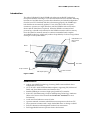
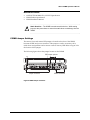
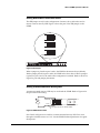
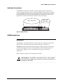
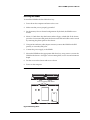
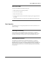
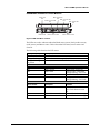
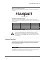
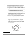
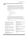
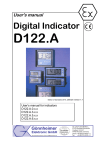
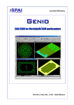
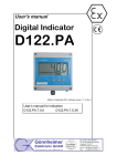
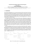
Adtron Corporation I35MB - 3.5” Mirrored Hard Disk Operations Manual March 2006 Rev. 003 PN: 610200094 ESD Warning Before handling the I35MB, or any media associated with the I35MB, ensure that you are working in an ESD-safe environment. Notice This manual describes the features of the Adtron I35MB. Adtron reserves the right to modify, amend, or in any way change the contents and/or products described herein, at any time, without notification. The information contained in this document is provided for reference only. Adtron Corporation does not assume any liability arising out of the application or use of the products described herein. This document may contain or reference information or products protected by copyrights or patents and does not convey any license under the patent rights of Adtron Corporation, nor the rights of others. Errors in this document may be reported in writing to the following address: Adtron Corporation 4415 E. Cotton Center Blvd. Phoenix, AZ 85040 Tel: 602-735-0300, Europe +41-56-496-5640 Fax: 602-735-0359, Europe +41-56-496-5648 www.adtron.com [email protected] Adtron Corporation is an ISO 9001:2000 certified company. Adtron logo is a trademark of Adtron Corporation. All other names mentioned are trademarks, registered trademarks, or service marks of their respective companies. 2006 Adtron Corporation. All rights reserved. Table of Contents Introduction 1 Aborting a button press I35MB Features 1 Related Documents 2 I35MB Jumper Settings 2 Setting Master/Slave and Cable Select 3 Setting a Remote-Mounted Activity LED 3 Interface Connectors 4 I35MB Installation 4 Introduction 4 Inserting the I35MB 5 Removing the I35MB 6 Basic Operation 6 Operating System Installation 6 I35MB LEDs and Mirror Control Buttons 7 Mirror Control Button Functions 8 Advanced Operations Using the I35MB Rail Kit 15 S.M.A.R.T. (Self-Monitoring, Analysis and Reporting Technology) Attributes 16 S.M.A.R.T Attribute Table 17 S.M.A.R.T Attribute Notes 18 LED Indicators 6 Partitioning and Formatting 14 19 IDLE State – No host access 19 ACTIVE State – Host access 20 I35MB Dimension Drawings 21 Appendix I 22 Sales and Technical Support 23 Standard Warranty 23 Revision Control 24 8 Managing Faults 8 Bank Hard Faults 9 Bank Soft Faults 9 Turning the Buzzer Off 10 Changing Media 10 Resetting Mirroring Indicators 12 Rebuilding a bank 13 Rebuilding a Bank Off-line 13 Using Different Size Media 13 i Rev. 003, PN: 610200094 Adtron I35MB Operations Manual Introduction The Adtron™ Diskpak™ Model I35MB with Adtron ActiveRAID™ technology incorporates RAID-1 mirroring in a 3.5-inch hard disk form factor. RAID-1 mirroring between two hard disk drives provides data redundancy and rebuild independent from the host CPU. With both disk drives functioning properly, the I35MB keeps both disk drives automatically updated. If one of the drives fails, the system continues to operate on a single disk drive until the I35MB is removed from the chassis and the failed drive is replaced. When the I35MB is reconnected and powered up, a rebuild can be initiated on the I35MB concurrent with host activity. Once the rebuild is manually started, it continues unattended until complete. ActiveRAID technology significantly reduces the probability of a data storage failure causing an overall system failure. LEDs, Buzzer, and Mirror Control buttons Bank 1 Bank 0 Flex Cable 40-pin Connector IDE Jumper Options Power Connector Figure 1 I35MB I35MB Features • • • • • • • • • Adtron ActiveRAID™ technology, featuring RAID-1 mirrored disk drives independent of host CPU ATA/ATAPI-5 ANSI NCITS340-2000 compliant; supporting PIO, Multiword DMA, and Ultra DMA interfaces and transfer rates Standard IDE 40-pin connector, high speed parallel ATA interface S.M.A.R.T. (Self-Monitoring, Analysis and Reporting Technology) Attributes (Refer to the section of this manual titled S.M.A.R.T. Attributes for more information) Audio and visual indicators warn of faults Operator initiated, automatic rebuild functions transparent to the host CPU Host operations continue with a single faulted disk drive or during a rebuild Full error detection and management without host intervention Field upgradeable firmware prevents future obsolescence 1 Rev. 003, PN: 610200094 Adtron I35MB Operations Manual Related Documents • • • ANSI NCITS 340-2000 ATA/ATAPI-5 Specification I35MB Product Specification I35MB Installation Manual Static Sensitive – The I35MB is a static sensitive device. While setting jumpers, take precautions to ensure that static does not discharge into the I35MB. I35MB Jumper Settings The master/slave and remote LED jumper is located on the front of the I35MB, between the IDE and power connectors. This jumper is used to set master, slave, cable select configurations and to mount a remote Activity LED. Refer to Figure 2 for the location of this jumper. The following figure shows the jumper location on the I35MB: IDE jumper options 39 1 40 2 40-pin connector 5 1 6 2 4 1 Power connector Figure 2 I35MB Jumper Locations 2 Rev. 003, PN: 610200094 Adtron I35MB Operations Manual Setting Master/Slave and Cable Select This IDE jumper is only for the configuration of master, slave, cable select and to mount a remote Activity LED. Figure 3 shows the pins of the IDE jumper on the I35MB. 7 5 3 1 8 6 4 2 Master Setting 7 5 3 1 8 6 4 2 Slave Setting 7 5 3 1 8 6 4 2 Cable Select Setting Figure 3 IDE Jumper When a jumper is placed on pins 3 and 4, the I35MB is the master device (default). With a jumper placed on pins 1 and 2, the I35MB is the slave device. When a jumper is placed on pins 1 and 3, the cable select configuration is utilized. Refer to the above Figure for pins and jumper placements. Setting a Remote-Mounted Activity LED A remote-mounted Activity LED may be used with the I35MB. Refer to Figure 4 for the pin location and setting. -EXTLED 7 5 3 1 8 6 4 2 +3.3V Through 120 ohm on-board resistor Figure 4 I35MB Remote LED Pins 5 and 6 in Figure 4 are used for a remote-mounted Activity LED. Pin 6 runs through a 120 Ohm resistor to +3.3V. See the I35MB Product Specification for signal descriptions. 3 Rev. 003, PN: 610200094 Adtron I35MB Operations Manual Interface Connectors The I35MB has an interface connector located on the front panel. Using an 80conductor cable (40-pin connector); connect the I35MB to the primary or secondary ports on the IDE controller. Plug a power cable from the computer’s power supply into the I35MB power connector. The I35MB does not require 12V. Refer to the Figure below, for the location 40-pin connector and power supply. 40-pin connector 4-pin Power connector Figure 5 I35MB interface I35MB Installation Introduction The I35MB is a 3.5-inch hard disk drive and mounts into a standard 3.5-inch hard disk drive bay. The drive may be mounted from the side or the bottom. DO NOT exceed the maximum insertion depth of 3.8mm [.150”] from drive edge. Consider the length of the screw used and thickness of the mounting surface. A common screw length of 3/16” is provided, but may not be correct in all applications. Refer to Figure 6 on page 5 for mounting hole locations. Static Sensitive - The I35MB is a static sensitive device. When installing and uninstalling the I35MB, take precautions to ensure that static does not discharge into the I35MB. 4 Rev. 003, PN: 610200094 Adtron I35MB Operations Manual Inserting the I35MB To install the I35MB in the hard disk drive bay: 1. Power down the computer and remove the cover. 2. Make sure that you are properly grounded. 3. Set the master/slave to desired configurations. By default, the I35MB is set to master. 4. Select a 3.5-inch drive bay that houses either a floppy or hard disk. If the chassis provides a front removable panel, the buzzer reset and fault LEDs can be viewed by removing the plastic panel on the chassis. 5. Using an 80-conductor cable (40-pin connector) connect the I35MB to the IDE primary or secondary IDE ports. 6. Connect the power supply to the I35MB. 7. Mount the I35MB into the appropriate disk drive bay, using screws to secure the I35MB in the chassis. See Figure 6 for mounting holes, screw size and maximum depth. 8. Put the cover on the chassis and screw it down. 9. Power on the computer. 6-32 x 3.8mm[.150"] MAX. DEPTH Figure 6 Mounting Holes 5 Rev. 003, PN: 610200094 Adtron I35MB Operations Manual Removing the I35MB To remove the I35MB from the hard disk drive bay: 1. Make sure that you are properly grounded. 2. Power down the computer. 3. Remove the chassis casing. 4. Disconnect the 80-conductor cable and the computer power supply cable from the I35MB. 5. Unfasten the mounting screws and remove the I35MB from the disk drive bay. Basic Operation The I35MB operates as a storage subsystem that can be used as a boot device or as additional storage. Partitioning and Formatting To the operating system, the I35MB looks like a single disk drive. All RAID-1 functions occurring in the I35MB are transparent to the operating system. Use the operating system utilities to partition and/or format the I35MB hard disk drive. Operating System Installation The I35MB can be formatted like any standard hard disk drive – bootable for operating system function or not bootable. Any standard disk partitioning and formatting utility can be used. Any operating system chosen that is compatible with IDE devices will be acceptable for use with the I35MB. The method of installing a specific operating system can vary, so consult the operating system documentation for instructions. 6 Rev. 003, PN: 610200094 Adtron I35MB Operations Manual I35MB LEDs and Mirror Control Buttons Activity LED Bank 0 Fault LED D12 D10 Bank 1 Access LED Bank 0 Access LED D13 Bank 1 Fault LED D11 D14 S4 Buzzer Reset S2 Bank 0 Mirror Control S3 Bank 1 Mirror Control Figure 7 LEDs and Mirror controls The LEDs are used to indicate individual Bank status (access/fault), media activity (read/writes) and Mirror status. Table 1 describes LED states, mirror status and controls. The following table describes the LED states: Activity LED (D10) Description Green Orange - flashing Orange – flashing in a set pattern No access; Power is on Reads or writes occurring on hard disk Indicates an issue with the I35MB Bank LED Description Color - State D11 D12 Bank 0 access Bank 0 fault D13 D14 Bank 1 access Bank 1 fault Green solid – Power on Orange solid – Hard fault Orange flashing – Soft fault Green solid – Power on Orange solid – Hard fault Orange flashing – Soft fault Mirror Control Description Function S4 Buzzer reset S2 S3 Bank 0 Mirror control Bank 1 Mirror control Audible alarm indicates error. Push button to turn off. Controls Bank 0 mirroring Controls Bank 1 mirroring Table 1 I35MB LED states and Mirror controls 7 Rev. 003, PN: 610200094 Adtron I35MB Operations Manual Mirror Control Button Functions The following figure shows the location of the mirror control buttons and LEDs on the I35MB. Bank 1 Mirror control Buzzer Reset Bank 0 Mirror control Figure 8 Mirror Control Button operations The following table describes the different operations using the Mirror Control button on either bank. Press and hold Mirror Control button to activate the functions listed in Table 2. Button Press Duration Bank Access LED Feedback Function 0 – 5 seconds 5 – 10 seconds 10 – 15 seconds 15 – 20 seconds > 20 seconds LED flashes slow (1/sec) LED flashes medium (2/sec) LED flashes fast (4/sec) LED solid on LED off Power up or down bank Mirror Rebuild No Operation Reserved No Operation Table 2 Mirror Control Button operations Functions marked reserved are for Adtron factory use only. Contact technical support for more details. In the case of a button press duration that reaches 15 seconds, DO NOT release until after 20 seconds to save future operations. Advanced Operations The individual banks may be taken off-line (powered down and/or replaced) at any time, for preventative maintenance or due to a failure. However, taking a bank offline automatically faults the mirror, requiring a rebuild. To clear a hard or soft fault, the rebuild must complete. Managing Faults The I35MB has two fault indicators: hard and soft. Refer to page 19, for the specific bank fault LED indicators to interpret these two types of faults. 8 Rev. 003, PN: 610200094 Adtron I35MB Operations Manual Adtron recommends having a system back-up available prior to managing hard or soft faults. Bank Hard Faults Hard fault errors may originate from any one of the following: • Write errors • Track 0 Not Found read error • HDD Timeout after a command If a hard fault occurs on one bank, the I35MB continues to read and write data to the other functioning bank. The I35MB is running in a degraded mode, which should be corrected as soon as possible. When the I35MB detects a hard fault, the faulted drive is taken offline and the RAID-1 operation between the drives is broken. The audible buzzer sounds and the bank fault LED turns solid orange. If this occurs, the faulted drive must be replaced. See Turning the Buzzer Off on page 10 for more information. Adtron recommends regularly backing up data; and, should a fault occur, scheduling a replacement and rebuild as soon as possible. If either a hard or soft fault occurs while the I35MB is running in a degraded mode, the I35MB sends an error code to the host and continues to operate. Bank Soft Faults Soft fault errors are caused by a read error on a drive. If a soft fault occurs, the I35MB continues to mirror data to both drives, but is running in a degraded mode, which should be corrected as soon as possible. The bank with the soft fault remains online with a continuously flashing orange bank fault LED. The soft fault can only be reset by rebuilding the faulted drive; or, replacing it and then performing a rebuild. Refer to Rebuilding a Bank on page 13. At this time, one of two actions is required: • Rebuild the faulted drive • Replace and rebuild the faulted drive 9 Rev. 003, PN: 610200094 Adtron I35MB Operations Manual Rebuilding the faulted drive may take several hours, depending on the size of the media and may result in a hard fault if the drive cannot “map” around any “bad” sectors. While rebuilding can result in a reliable storage device and workable drive, Adtron recommends replacing the drive in the field that exhibits a soft fault and then rebuilding and testing this drive in a noncritical test environment to determine if this drive can be used as a spare. Turning the Buzzer Off The audible buzzer goes off when a hard fault occurs on one of the two disk drives. When a hard fault occurs, the RAID-1 mirror is broken and maintenance is required. To turn the buzzer off: 1. If possible, pop the removable plastic panel off the drive bay in which the I35MB is installed. If the I35MB does not have front access through a drive bay, continue with Changing Media on this page. 2. Depress the Buzzer Reset button, labeled S4 in Figure 7 on page 7. 3. Note the bank number, 0 or 1, with the fault LED turned solid orange. This is the bank that requires attention. 4. Schedule a time to power down the computer and remove the I35MB. Changing Media Static Sensitive - The I35MB is a static sensitive device. Take precautions to ensure that static does not discharge into the I35MB. To change the bank with the fault: 1. Make sure you are appropriately grounded. 2. If accessible from the front cover, pop the faceplate off the bay with the I35MB inserted. Push the Buzzer Reset button (S4) on the I35MB to turn off audible alarm, if applicable. 10 Rev. 003, PN: 610200094 Adtron I35MB Operations Manual 3. Note the bank number, 0 or 1, with the fault LED turned solid orange. This is the bank that requires attention. 4. Power down the computer. 5. Remove the computer cover and locate the I35MB in the disk drive bay. 6. Disconnect the power supply and 80-conductor cable from the I35MB. 7. Unscrew the chassis mounting screws and slide the I35MB out of the disk drive bay. 8. On the side opposite the flex cables, loosen the retaining screw for the faulted disk drive. 9. Gently unseat the drive to a disengaged distance, approximately ¼ of an inch, causing the flex cables to bow in a loop. (Refer to Figure 10.) Carefully disconnect the flex cable from the faulted disk drive. Detaching the drives from the flex cable in a forceful manner will damage the flex cable. Flex Cable IDE Connector Bank 0 Bank 1 Bank 1 Bank 0 Retaining Screws IDE Connector Flex cables are extremely fragile and should be handled with care when attaching, reattaching and/or disconnecting. Not doing so will cause irreversible damage. If during any of the actions listed, the flex cable becomes damaged or unusable, please contact Adtron Technical Support. Figure 9 Flex Cable and Retaining Screws 10. Slide the drive out of its carrier. 11. Insert a new, working disk drive of the same capacity (or greater) with rails installed into the carrier. Flex Cables Figure 10 Flex Cable View 11 Rev. 003, PN: 610200094 Adtron I35MB Operations Manual 12. Before the disk drive is fully seated (approximately ¼ of an inch to the drive being fully seated) re-attach the flex cable to the disk drive. Refer to Figure 10 for a view of this procedure. Carefully align and slowly attach. Pay close attention to mounting the flex cable. Ignoring this procedure and caution can lead to damage in future operations. 13. Tighten the retaining screw for the new disk drive. 14. The I35MB may be re-inserted in the disk drive bay, as described in Inserting the I35MB on page 5 of this document. If your computer system does not provide front access to the I35MB when it is installed in the bay, then connect the I35MB to the primary or secondary ports on the IDE controller and power cable external to the computer system to do the rebuild. The front LEDs and buttons must be available to do the rebuild. 15. After securing the I35MB, a rebuild must be performed. Go to Rebuilding a Bank on page 13. Resetting Mirroring Indicators The procedure below provides steps to reset the mirror indicators on the I35MB. These steps address mirror indicators and DO NOT address resetting mirroring data or data equilibrium. In addition, following these steps will only ensure subsequent writes will be mirrored. For more information on resetting mirroring operations beyond mirror indicators, refer to the section of this manual titled, Rebuilding a Bank, on page 13. Static Sensitive - The I35MB is a static sensitive device. Take precautions to ensure that static does not discharge into the I35MB. To reset mirror operations and change both banks: 1. While power is OFF, verify both banks are unpopulated. 2. Cycle the I35MB power to the ON state (for 5 seconds or more), then the OFF state. 3. Insert media into desired banks. 4. Cycle power ON. 5. Once powered ON, all subsequent writes will be mirrored. 12 Rev. 003, PN: 610200094 Adtron I35MB Operations Manual Rebuilding a bank After a bank has been replaced, a rebuild must be performed. To start a Bank Rebuild, press the mirror control button between 5 and 10 seconds on the off-line bank. Release the button when the Access LED starts flashing at 2 blinks per second. The rebuild process begins, indicated by the Access LED turning solid green and the Fault LED flashing green. When complete, the Fault LED changes from flashing green to off. It is faster to do the rebuild when there is no host activity to the I35MB. A rebuild operation copies the contents of the entire media at a rate of roughly 5 MB/sec, requiring several hours for large capacities. Depending on concurrent host activity, the rebuild process may be slowed. The higher the level of concurrent host activity, the more the rebuild process may be impacted (slowed). Rebuilding a Bank Off-line Only the power connection is required to do the rebuild if you want to have a rebuild complete before bringing the drive on line. No host activity interruption results in the fastest rebuild time. Using Different Size Media The I35MB can support different size drives in each bank and still operate the mirroring function. The rules for this operation are as follows: Media inserted to replace the factory original must have a capacity that is equal to or greater than the original media size. The capacity of the mirrored unit remains the same size as when shipped from the factory. In other words, if the drive shipped from the factory with a capacity of 20GB, it will retain that capacity regardless of the actual capacity of the media in either bank. Any media inserted into a bank that is smaller than the original capacity can not be used for mirroring. Rebuild attempts to a smaller media will not start. The LEDs will indicate a mirror fault condition. 13 Rev. 003, PN: 610200094 Adtron I35MB Operations Manual Examples: A new I35MB is installed in the field with two 20GB capacity media for 20GB of mirrored storage. Bank 1 requires replacement. A 10GB media is installed and the button pressed for rebuild. Rebuild will not start and the mirror remains broken. A 40GB media is then inserted in Bank 1. The rebuild copies the data from the Bank 0 20GB drive to the new drive in Bank 1. The I35MB remains a 20GB mirrored device. Bank 0 media is replaced with a 60GB unit. The rebuild copies the operational 20GB from Bank 1. The I35MB now has a 40GB media in the Bank 1 and a 60GB drive in Bank 0. The I35MB remains a 20GB mirrored device. Contact Adtron Technical support for more information regarding using different size media. Aborting a button press If the bank button is pressed for longer than 20 seconds, no operation is performed. This is provided as an opportunity to abort a button press. 14 Rev. 003, PN: 610200094 Adtron I35MB Operations Manual Using the I35MB Rail Kit The following steps describe the process to disassemble and reassemble hard disk drives on the I35MB. Attention to individual instructions is necessary to ensure functionality and avoid damage to the device. Please contact Adtron Sales if assembling hard disk drives other than those provided by Adtron, and refer to the section of this manual titled, Using Different Size Media. Refer to Appendix # 1 for a list of supplies that are included with the I35MB Rail Kit Installation. Static Sensitive - The I35MB is a static sensitive device. Take precautions to ensure that static does not discharge into the I35MB. 1. Position rail retention screw (#1) through left rail (#2), align screw with corresponding hard disk, bottom side mounting hole and screw gently into place (avoid tightening screw until second retention screw is also aligned and screwed into place). Firmly tighten both screws but do not over tighten. 2. Repeat assembly sequence from step 1, with the right rail (# 3). Align the drive assembly retention screw (# 4) with the left rail (# 2) as illustrated and screw gently into place. Avoid tightening the drive assembly screw until step 4. 3. Adhere chassis ground protection barrier1 (# 5) to the rear edge of the drive. 4. Align the completed hard disk drive assembly on the I35MB guide rails and slide into place. Attach the drive power and signal flex cable, which will require pulling the drive slightly out to accommodate assembly. Lastly, gently tighten the drive assembly retention screw into place, ensuring drive does not extend beyond the I35MB footprint, then firmly tighten the screw. Refer to Changing Media, on page 10, for detailed instructions for attaching flex cables and connecting the hard disk drive. 3 1 4 2 5 Figure 11 I35MB Rail Kit 1 Important: Should a drive be replaced and a new drive assembled with the original I35MB Rail Kit, a new chassis ground protection material will be required. For example, Adtron suggests Kapton tape. 15 Rev. 003, PN: 610200094 Adtron I35MB Operations Manual S.M.A.R.T. (Self-Monitoring, Analysis and Reporting Technology) Attributes The Adtron Diskpak I35MB incorporates an array of S.M.A.R.T. attributes and capabilities that provide significant amounts of information relating to the life history of the hard disk drive (HDD). S.M.A.R.T. is a monitoring system for computer (HDDs) to detect and report on various indicators of reliability, with the intent of anticipating failures. The user or system administrator can send a query using S.M.A.R.T. technology to retrieve requested data. This provides time to anticipate drive failure and to take preventive action — such as copying the data to a replacement device. The I35MB incoporates: • Operational Attribute Data • User and manufacturing log pages • Error Log pages • Self-test Using RAID-1 mirroring techniques, the I35MB duplicates data using two disk interfaces that are referred to as Bank 0 and Bank 1. The user can determine the status of the data mirror as a whole, as well as each bank individually, using industry- standard S.M.A.R.T commands. The S.M.A.R.T. Attributes that specifically apply to the I35MB are summarized below, and a more detailed description appears in Table 3. Contact Adtron for more S.M.A.R.T. details. Attribute #110: Hardware Configuration: Attribute identifies configuration as RAID-1 and identifies the media interfaces that exist. Attribute #111: Media Presence: Attribute identifies whether media was present on those interfaces at last power-up. Attribute #112: Reset to Ready Timer: Attribute identifies the time in milliseconds from power-up until this logical unit indicated it was ready. Attribute #113: Rebuild Activity Completion Estimate: Attribute provides an estimate of the percentage of time remaining until the rebuild activity is complete. Attribute #120: Hard Fault – all Media: Attribute identifies all the media that has experienced a hard fault. 16 Attribute #121: Hard Fault – Bank 0: Attribute identifies the Bank 0 media that has experienced a hard fault. Attribute #122: Hard Fault – Bank 1: Attribute identifies the Bank 1 media that has experienced a hard fault. Attribute #125: Soft Fault – all Media: Attribute identifies all the media that has experienced a soft fault. Attribute #126: Soft Fault – Bank 0: Attribute identifies the Bank 0 media that has experienced a soft fault. Attribute #127: Soft Fault – Bank 1: Attribute identifies the Bank 1 media has experienced a soft fault. Rev. 003, PN: 610200094 Adtron I35MB Operations Manual S.M.A.R.T Attribute Table S.M.A.R.T attributes are vendor specific parameters that are used in evaluating the status of the device. Adtron specific S.M.A.R.T attributes are listed below. Many tools used to display S.M.A.R.T. attributes may not recognize Adtron specific attributes. Refer to Table 3 to identify Adtron specific S.M.A.R.T. attributes. Attribute Number (8 bits) Name Value (8 bits) Raw Data (eight, 8-bit bytes) Reserved for future use Reserved for future use 1: RAID-0 64-bit field showing which 2: RAID-1 media interfaces are present Threshold 9 (0x09) 12 (0x0C) 110 (0x6E) Power on hours Power cycle count Hardware configuration 111 (0x6F) 112 (0x70) Media presence 0 Reset to ready 0 113 (0x71) Rebuild remaining 0 120 (0x78) 121 (0x79) Hard fault (all media) Hard fault (1st member) 199 (Note 120a) (Note 120b) 122 (0x7A) Hard fault (2nd member) (Note 120a) (Note 120b) 123 (0x7B) Hard fault (3rd member) 200: all media OK <200: some bad 200: all mirrors OK <200: some bad 200: all mirrors 64-bit field showing which OK media <200: some bad Reserved for future use (Note 120a) (Note 120b) 125 (0x7D) Soft fault (all media) 200: all media OK <200: some faulted 198 (Note 120a) (Note 120b) 126 (0x7E) Soft fault (1st member) (Note 120a) (Note 120b) 127 (0x7F) Soft fault (2nd member) (Note 120a) (Note 120b) 128 (0x80) Soft fault (3rd member) (Note 120a) (Note 120b) 0 (Note 110) 64-bit field showing which media are present Time from start to reset process to when this LU indicated READY in the host interface, milliseconds 16-bit value: 0x0000: no rebuild activity 0xFFFF: rebuild starting else: “percent” (ffff..0) remaining 64-bit field showing which media 64-bit field showing which media (Note 112) 64-bit field showing which media 200: all mirrors 64-bit field showing which OK media <200: some faulted 200: all mirrors 64-bit field showing which OK media <200: some faulted Reserved for future use 17 0 0 0 0 0 0 0 Rev. 003, PN: 610200094 Adtron I35MB Operations Manual Attribute Number (8 bits) 194 (0xC2) 199 (0xC7) Name Value (8 bits) Raw Data (eight, 8-bit bytes) Threshold Temperature Degrees C (Note 194) 0 UltraDMA error count 0 Unsigned integer 0 (Note 199) Table 3 S.M.A.R.T. Attributes S.M.A.R.T Attribute Notes Note Description 110 This value does not conform to the ATTRIBUTE value/threshold model. The value literally indicates the number of members in each mirror set. The reset-to-ready attribute reports elapsed time from start of hard reset to the end of hard or soft reset. If a soft reset is received, the value could be quite large and misleading. This attribute only available in mirrored units. 1st, 2nd, 3rd refer to mirror banks. For RAID-0, only Bank 1 exists; for RAID-1, Banks 0 and 1 exist; more banks are defined for future expansion, but not currently implemented. Adtron temperature can report negative values, and other manufacturers cannot. The attribute value is degrees C, and the first byte of the raw data field is fractional degrees C. For example, value = 0x20 and raw [0] = 0x80 means 0x20.80 (hexadecimal), or 32.5 decimal. The DMA error counter is reset to zero with any hard reset. 112 120a 120b 194 199 Table 4 S.M.A.R.T. Attribute Notes 18 Rev. 003, PN: 610200094 Adtron I35MB Operations Manual LED Indicators IDLE State – No host access Bank Access LED (Green/Orange) Bank Fault LED (Green/Orange) Drive Activity LED (Green/Orange) GREEN GREEN flashing (1/sec) OFF OFF OFF OFF GREEN GREEN OFF ORANGE GREEN GREEN GREEN flashing (1/sec) OFF See Note 1 GREEN OFF ORANGE OFF ORANGE GREEN Drive reinserted OFF Request rebuild GREEN flashing (2/sec) Rebuilding GREEN ORANGE See Note 1 GREEN GREEN Rebuild complete Soft Fault GREEN OFF GREEN GREEN GREEN Hard Fault OFF ORANGE flashing (1/sec) ORANGE Bank State Normal Request off-line Fully off-line Fully off-line, faulted Request on-line Becoming online Drive removed GREEN flashing GREEN (2/sec) GREEN Description No host access Button pushed while on-line. Replace drive and rebuild (Hard fault). Button released, processing Replace drive and rebuild. Must perform rebuild Button released, processing. May take 6 hours or more. Immediately resume normal operations. Bank read fault Replace drive and rebuild. Table 5 Inactive LED states 1 Depends on previous LED state: OFF = Online, ORANGE = Fault. 19 Rev. 003, PN: 610200094 Adtron I35MB Operations Manual ACTIVE State – Host access Bank State Bank Access LED (Green/Orange) Bank Fault LED (Green/Orange) Drive Activity LED (Green/Orange) Normal GREEN OFF ORANGE OFF ORANGE OFF ORANGE OFF See Note 1 ORANGE ORANGE OFF ORANGE ORANGE ORANGE ORANGE ORANGE See Note 1 ORANGE GREEN flashing (2/sec) ORANGE Request off-line GREEN flashing (1/sec) Becoming offGREEN line Fully off-line OFF Request on-line GREEN flashing (1/sec) Becoming onOFF line Drive removed OFF Drive OFF reinserted Request rebuild GREEN flashing (2/sec) Rebuilding GREEN Description Host access in progress (reads or writes) Button pushed while online. Button released, processing request. Button released, processing. Replace drive and rebuild. Must perform rebuild. Rebuild complete Soft Fault GREEN OFF ORANGE GREEN ORANGE Hard Fault OFF ORANGE flashing (1/sec) ORANGE Button released, processing. May take 6 hours or more. Immediately resume normal operations. Bank read fault. ORANGE Replace drive and rebuild. Table 6 Active LED states 1 Depends on previous LED state: OFF = Online, ORANGE = Fault 20 Rev. 003, PN: 610200094 Adtron I35MB Operations Manual I35MB Dimension Drawings 25.3 .997 146.1 5.750 6-32 x 3.8[.150] MAX. DEPTH (3X) 101.6 4.000 Figure 11 I35MB 21 Rev. 003, PN: 610200094 Adtron I35MB Operations Manual Appendix I The table below lists the parts supplied on the I35MB Rail Kit. Items numbers correspond with Figure 11, under the section of this document titled, Using the I35MB Rail Kit. Item Number Quantity Description #1 #2 #3 #4 #5 Four (4) One (1) One (1) One (1) Two (2) Rail Retention Screw (M3 x 5) Rail – Left Rail – Right Drive Assembly Retention Screw (M2. 5x9) Chassis Ground Protection Barrier Table 7 Parts Supplied 22 Rev. 003, PN: 610200094 Adtron I35MB Operations Manual Sales and Technical Support Contact Adtron Corporation for technical support, application questions, data sheets, and documentation. Our normal business hours are Monday through Friday, 8am to 5pm, MST. Headquarters – Sales Europe - Sales Adtron Corporation 4415 E. Cotton Center Blvd. Phoenix, AZ 85040 Tel: +1-602-735-0300 Fax: +1-602-735-0359 Web: http://www.adtron.com Email: [email protected] Tel: +41-56-496-5640 Fax: +41-56-496-5648 Email: [email protected] Nordic - Sales Tel: +45-4557-0754 Fax: +45-4557-0753 Email: [email protected] Germany – Sales Tel: +49-821-589-9914 Fax: +49-821-589-7190 Email: [email protected] United States – Technical Support Europe – Technical Support Tel: +1-602-735-0300 Fax: +1-602-735-0359 Email: [email protected] Tel: +45-4557-0754 Fax: +45-4557-0753 Email: [email protected] Web Site Web: http://www.adtron.com/support Standard Warranty Adtron warrants this product to be free from defects in materials and workmanship for the duration of the warranty period. If this product fails within the warranty period due to such defect, Adtron will repair or replace this product. This warranty does not apply if this product has been damaged by abuse, accident, disaster, misuse or incorrect installation. 23 Rev. 003, PN: 610200094 Adtron I35MB Operations Manual Revision Control Rev Author Date Sections Description 001 002 003 JMH JMH JMH Apr 2005 Aug 2005 Mar 2006 All Connector SMART, Rail Kit Original 8-pin change to the connector Adding SMART attributes/ and information. Rail Kit guide. 24 Rev. 003, PN: 610200094