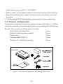
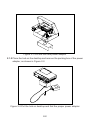
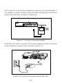
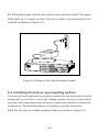
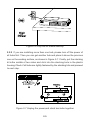
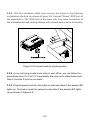
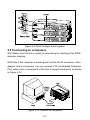
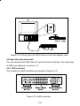
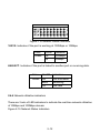
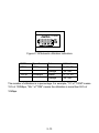
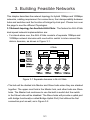
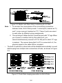
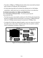
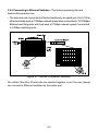
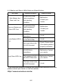
1
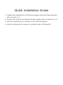
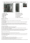
ALH-616ds
AcerHub
Dual-Speed Ethernet Hub
User's Guide
Quick Installation Guide
1. Unpack the AcerHub ALH-616ds dual-speed Hub and it'saccessories
(refer section 1.3).
2. Connect the Hub to the external Power supply (refer to section 2.4.1)
3. Use the normal ports to connect to PCs and computers.
4. Use the uplink port to connect to another hub or LAN switch.
1.Overview
Congratulations on your purchase of the AcerHub 616ds. The AcerHub ALH-
616ds is a 16-port dual-speed fast Ethernet repeater hub for connection with
multiple PCs to a workgroup LAN (Local Area Network) environment to
sharenetwork resources.
1.1 Product goal
AcerHub ALH-616ds provides high-speed and easy access to the LAN and
Intranet both for SOHO (Small Office/ Home Office) and corporations. Itallows
data transmission at speeds of 10 Mbps or 100Mbps, depending if theconnected
device is running at 10Mbps or 100Mbps. Besides the high-speed data
access, the AcerHub ALH-616ds also supports one uplink port for Class-II
cascading connection between hub stacks. The uplink port will support the
bridge function that permits a distance of 100 meters for data transmission
in Class-II cascading and eliminates the repeater count limitation in IEEE
802.3u specifications. It will be easy to construct your own LAN with ALH616ds by this explicit expanding capability of data transmitting distances and
user accounts.
Installation of AcerHub ALH-616ds is relatively simple and all you have to
dois plug the cables from the adapter cards to the ports, check the LEDs
and you can start networking.
1.2 Product Features
AcerHub ALH-616ds provides the following features:
• 16-port dual-speed hub, each port is a 10/100 Mbps dual-speed connection
with network speed auto-detection
• Fully complies with IEEE 802.3 and 802.3u specifications
• Built-in switching function to connect 10 and 100Mbps network domains
• Stackable function to provide maximum stacking of 5 sets as a single hub
count by SCSI-II cables
• In slave hub mode, an uplink port with bridge function which provides
scalable network expansion.(This function is very useful in constructing a
1-1
large network,refer section 3.1 for details.)
• Built-in switch auto-disable function to avoid data looping when stacking
• External switching power supply for lower power consumption and heat
emission
• Compact design for SOHO desktop environment for easy networking
1.3 Product configuration
The product configuration inside the package is shown in the figure 1-1.Please
check the contents of the package if there is any missing part beforeusing
the hub. The accessories of this product include:
ALH-616ds dual-speed hub
1 piece
External switching power adapter
1 piece
Power cord
1 piece
Stacking cable (SCSI-II)
1 piece
Stacking kit 1 pairUser's manual
1 piece
ALH-616ds
Figure 1-1Product configuration of AcerHub ALH-616ds
1-2
2.Make Your Hub Ready
This chapter will guide you through how to install the AcerHub ALH-616ds.
It includes procedures for connecting to the external power supply, installing
the hub on your working surface, connecting the Hub to your computer, and
guidelines to see if it works well. Before setting up your hub, please take
note of the front and rear panel of this hub, as shown in Figure 2-Aand 2B.
Figure 2-A Front Panel
Note:The ports marked "I",", "2", "3", "4", "5", "6", "7","8"
"9",", "10", "11", "12", "13", "14", "15","16"are normal ports.
Please follow the installing procedures to make your network ready:
2.1 Connecting to the external power supply
Carefully unpack the AcerHub ALH-616ds and it's accessories. For the first
time that you use this hub, please make sure there is nothing missing in the
package. The procedures for connecting to the power outlet are:
2.1.1 Take out the hub and the power adapter from the packing box, as shown
in Figure 2-1.
2-1
Figure 2-1 Get the hub and power adapter
2.1.2 Place the hub on the desktop and remove the packing box of the power
adapter, as shown in Figure 2-2.
Figure 2-2 Put the hub on desktop and find the proper power adapter
2-2
2.1.3 Verify it's a 5V,3A power adapter by looking at the indicating label. If
the adapter is correct, please stretch the cable and plug the cord into the
power jack of the hub, as shown in Figure 2-3.
AcerSOHO
Series
Figure 2-3 Connect to the power adapter
2.1.4 Once the hub is connected to the power adapter, please connect the
power adapter to a power cord, as shown in Figure 2-4.
Figure 2-4 Connect to the power cord to wall outlet
2-3
2.1.5 Plug the power cord into the outlet on the wall and check if the power
LED lights up. If it lights up, then the hub is ready to be connected to the
network, as shown in Figure 2-5.
Figure 2-5 Power on the hub and make it ready
2.2 Installing the hub on your working surface
You have to find a solid working surface to place the hub and make sure the
equipment is not close to any high voltage power source or over-heated
sources. Also keep away from electronic equipment sensitive to electronic
interference. The brief procedures of installing your hub should be:
2.2.1 Put the hub on a stable working surface, as shown in Figure 2-6.
2-4
Figure 2-6 Lay hub on stable desktop
2.2.2 If you are installing more than one hub, please turn off the power of
all hubs first. Then you can get another hub and place it above the previous
one on the working surface, as shown in Figure 2-7. Finally, put the stacking
kit inthe middle of two sides and click into the stacking hole in the plastic
housing.Check if all hubs are tightly fastened by the stacking kits and proceed
to next step.
AcerSOHO
Series
AcerSOHO
Series
Figure 2-7 Unplug the power,and stack two hubs together
2-5
2.2.3 Get the stackable cable and connect the cable to the stacking
connectoron the hub, as shown inFigure 2-8. Connect "Down" SCSI port of
the upperhub to "Up" SCSI port of the lower hub. Any loose connection of
the stackablecable will cause problems with network performance and quality.
Figure 2-8 Connect hubs by stacking cable
2.2.4 If you are trying to add more hubs in your office, you can follow the
procedures from 2.2.2 to 2.2.3 repeatedly. Be sure not to stack hubs more
than 5 (include 5) sets in one stack.
2.2.5 Plug the power cord into the outlet on wall and check if the power LED
lights up. The hub is ready for network connection if the power LED lights
up,as shown in Figure 2-9.
2-6
Figure 2-9 Stack multiple hubs together
2.3 Connecting to computers
2.3.1 Make sure the hub is ready for networking by checking if the PWR
indicator displays.
2.3.2 See if the computer is working and find the RJ-45 connector of the
adapter card in computers. You can connect UTP (Unshielded Twistered
Pair) cables from normal ports of the hub to computers directly, as shown
in Figure 2-10.
Figure 2-10 Connect to computers
2-7
2.3.3 Arrange the route for cabling if no fixed cabling box is provided.
Otherwise, It's right way to connect from your computer to the fixed cabling
box on your working surface and plug the other end of the cable to the RJ45 connector on the hub, as shown in Figure 2-11.
Figure 2-11 Connect UTP cable from hub to computers
2.3.4 After connecting to the hub, please check if the Link LEDs on the
adapter card and the hub(named as LNK/ACT) are lit up, as shown in Figure
2-12. If the LED is not lit up, there must be something wrong and please
reference to chapter 4 for quick trouble shooting.
2-8
ACT
ALH-616ds
Figure 2-12 Check the Link LEDs both on hub and adapter card
2.4 Does the hub work well?
You can observe the LED status to see if the hub works fine. The meanings
of LEDs are defined in section 2.4.1.
2.4.1 LED overview
The locations of LED indicators are shown in Figure 2-13.
Figure 2-13 LED overview
2-9
There are three groups of LED indicators in the front panel:
• System status indicators: Indicate the overall system status of the hub.
It includes system PWR, Fan Err., Master, Slave indicators, Collision of
10 and 100M, and Bridge function
• Network status indicators: Indicate working status of each connection port,
It includes port 100/10M, LNK/ACT
• Network utilization indicators: Indicate the bandwidth utilization of 10 and
100Mbps. It includes 5, 15, 25, 35, 55+ scales indicators
2.4.2 System status indicators
Figure 2-14 System Status Indicators
PWR: Indicates if the system is provided with power.
Color
Green
On/Off
On
Off
Indication
System Powered
No Power
FAN Err.: Indicates if the cooling FAN is dead.
Color
Orange
On/Off
On
Off
Indication
FAN is dead
Normal
Master/Slave: Indicates if the system is stacked to be the Master or Slave
hub.
2-10
Note: It's normal either Master or Slave LED will display when hubs
are stacking.
Master
Color
Green
Slave
Green
On/Off
On
Off
On
Off
Indication
Master
Malfunction
Disable
Malfunction
Note: The difference between Master hub and Slave hub will be
explained in chapter 3.
Collision: Indicate if a collision occurs in 10Mbps or 100Mbps domain.
Color
On/Off
10 Collision Orange Blink
Off
100 Collision Orange Blink
Off
Indication
Collision in 10Mbps domain
Normal
Collision in 100Mbps domain
Normal
Bridge: Indicates if the bridging function is enabled.
Color
Green
On/Off
On
Off
Indication
Bridge function enabled
Bridge function disabled
Note: The slave hub will provide a Bridge Uplink Port, see chapter 3 for
details
2.4.3 Network Status Indicators
There are 3 LED indicators to indicate the network status of each connection
port.
2-11
4
6
8
Figure 2-15 Network Status Indicators
100/10: Indicates if the port is working at 100Mbps or 10Mbps.
Color
Green
On/Off
On
Off
Indication
100Mbps
10Mbps
LNK/ACT: Indicates if the port is linked to another port or receiving data.
Color
Green
On/Off
On
Blink
Off
Indication
Link succeeds
Receiving
Link fails
2.4.4 Network utilization indicators
There are 2 sets of LED indicators to indicate the real-time network utilization
of 10Mbps and 100Mbps domain.
Figure 2-15 Network Status Indicators
2-12
616ds
Figure 2-16 Network utilization indicators
ROW
10 M
Speed
10Mbps
100 M
100Mbps
Color
Green
Orange
Green
Orange
Utilization
5, 15, 25
35, 55+
5, 15, 25
35, 55+
The number of utilization is in percentage. For example, "15" of "100M" means
15% of 100Mbps, "55+" of "10M" means the utilization is more than 55% of
10Mbps.
2-13
3. Building Feasible Networks
This chapter describes the network topology for hybrid 10Mbps and 100Mbps
networks, cabling requirement for connections, the interoperability between
hubs and switches and the function of bridge Up-Link port. Please turn over
the page to see the different Topologies.
3.1 Network topology for AcerHub ALH-616ds : The factors for ALH-616ds
dual-speed network implementation are:
• For stand-alone one, the ALH-616ds consists of separate 10Mbps and
100Mbps network domains with one built-in switch to inter-connect the
data in domains, as shown in Figure 3-1.
616ds
Figure 3-1 Separate domains in ALH-616ds.
• The hub will be divided into Master and Slave hubs when they are stacked
together. The upper most hub is the Master hub, and other hubs are Slave
hubs. The Master hub continues to use the built-in switch but the switch
in the Slave hubs will be disabled. The Slave hubs will provide a uplink port
with bridge functional(so called Bridge Uplink Port) that utilizes the first
connection port as well, as in Figure 3-2.
3-1
Figure 3-2 Master and Slave hubs in stacking ALH-616ds.
Note: 1. To concern the convenience of the cross-wiring connection
between hubs, ALH-616ds provide 1 normal port (marked as "II)
and 1 cross-over port (marked as "X"). These 2 ports are wired
to each other by different wiring assignments.
2. The up-link port utilizes the first connection port with "X" sign.When
you connect to another hub by this uplink port, you
cannot simultaneously connect a PC to this port in which "II" sign
is marked . The reason being that if a PC is connected to it, the
physical signal in the cable will be corrupted.
• The built-in switches in slave hubs will be disabled automatically to avoid
data looping from multiple inter-connections of hubs, as shown in Figure
3-3.
Figure 3-3 Auto Data looping prevention in ALH-616ds.
3-2
• By way of an uplink port with a Bridge function, the limitations on 100Mbps
hub count(maximum 2) can be eliminated. The hub count is unlimited and
cable length between hubs can reach 100 meters, as shown in Figure 34.
Figure 3-4 Unlimited cascading of ALH-616ds.
• All PCs with 10Mbps network adapter cards transmit data at 10Mbps and
form the 10Mbps network domain, as shown in Figure 3-5.
• PCs with 10/100Mbps network adapter cards will auto-negotiate and switch
the network speed to 100Mbps. They transmit data at 100Mbps and form
the 100Mbps network domain, as shown in Figure 3-5.
Figure 3-5 Network domains and bridged uplink.
3-3
• The data in 10Mbps or 100Mbps domain will be inter-connected by internal
built-in switch in the Master hub consequently.
• All hubs delivering data by the shared-bus always work on half-duplex
mode;that is, data can be sent or received at one time in one direction.
3.2 Interconnection to Hubs and Switches
3.2.1 Connecting to Ethernet Hubs : The factors governing hub
interconnection are:
• The hubs are only connected by uplink port. ALH-616ds will automatically
transmit at 10Mbps network speed when connecting to 10Mbps Ethernet
hubs and 100Mbps network speed if connected to 100Mbps hubs.
• If multiple ALH-616ds are stacked together, users can connect to hubs by
the uplink port in slave hubs. Therefore other hubs can perform another
class-II cascading, as shown in Figure 3-6.
Figure 3-6 Connect to Ethernet Hubs.
3-4
3.2.2 Connecting to Ethernet Switches : The factors governing hub and
switch interconnection are:
• The hubs are only connected to Ethernet switches by an uplink port. ALH-616ds
will automatically work at 100Mbps network speed when connected to 10/100Mbps
Ethernet switching ports and it will work at 10Mbps network speed if connected
to 10Mbps switching ports.
Figure 3-7 Connect to Ethernet Switches.
No matter if the ALH-616ds hubs are stacked together or not, the user always
can connect to Ethernet switches by the uplink port.
3-5
4. Troubleshooting
4.1 Symptoms and Suggestions
Symptoms
All LEDs are
off
Possible Reason
The hub is not receiving
DC power
Link LED of a 1.The UTP cable is not
connected
securely connected
port is off
2.The port is bad
3. If the other party is a
PC, the Network
interface card(NIC)
could be not working
4. If the other party is a
hub or LAN switch, the
connected ports signal
could be cross-over
100 LED is
not lit when
connected to
a 100 NIC or
100 Hub(but
Link LED is
lit.)
Suggestions
1. Check if the AC power cord
is securely fastened at both
ends ands that power is
available at the AC outlet.
2. Check if the power adapter
DC 5V cord is connected to
Hub's DC jack
1. Check the cable connection
2.Try to connect another port
3. Check if the network
interface card(NIC)is
installed properly
4. Make sure ALH-616ds
normal port is connected to
the other hub's(or
switch's)uplink port(or called
cross-over port); and ALH616ds uplink port is
connected the other's
normal port
5. Try another normal cable
5. The UTP cable is
broken, or it is a crossover cable
1. Un-plug the UTP cable from
The auto-negotiation
ALH-616ds, and plug-in
function is failed between
again
ALH-616ds and the other
2. Check if the NIC is set to
party
anto-negotiation mode
3. Check if the other hub is set
to auto-negotiation mode
4. if the above steps does not
work, it is an interoperability problem, contact
your vendor
4-1
4.2 Master and Slave LEDs State and Result/Action
LED state
Stacking condition
For all ALH-616ds
Both Master And
,both standalone
Slave Led lit on
and stacking
condition
For all ALH-616ds
None or Master and
,both standalone
Slave LED lit on
and stacking
condition
ALH-616ds is
standalone
the uppermost hub
only Master LED lit
in the ALH-616ds
Result & action
Malfunction,
Contact your
vendor
Malfunction,
Contact your
vendor
it is ok
it is ok
on
the lower hubs in the
ALH-616ds stack
only Slave LED lit on
Check, Please check
if the stacking cable is
properly connected
ALH-616ds is
Malfunction Contact
standalone
your vendor
The uppermost hub in
Malfunction Contact
the ALH-616ds stack
your vendor
The lower hubs in the
ALH-616ds stack
it is ok
If you have any problem in building your network with AcerHub ALH-616ds,
please contact your Vendor or visit our website:
Http:// www.acernetxus.com.tw
4-2
Appendix A.Specifications
Network Interface
16-port 10/100 dual-speed auto-detection function
• 10Mbps Ethernet IEEE 802.3 10Base-T
• 100Mbps Ethernet IEEE 802.3u 100Base-TX
One of the ports(Port NO.1)has two RJ-45 connector to provide
either normal or uplink connection.
Physical Dimension (From front View)
Width
247 mm
Depth
163 mm
Height
45 mm
Weight
1.5 Kg
Environmental Operating Range
Operating Environment
0°C to 55°C (32°F to 131° F)
Operating Humidity
20% to 80% non-condensing
Network Cable Specification
UTP Category 5 LAN cable of EIA/TIA-568 and EIA/TIA TSB-36
specifications for 100Mbps
Stacking Specification
Maximum stacking of 5 sets as a single hub count by SCSI Cables
SCSI-II 50-pin connection cable of 100 mm long
External Switching Power Adapter
Operating AC power voltage 100~120/220~240V AC Auto-switching
Output DC power voltage 5V, 3A maximum
EMI Certifications
FCC
Part 15, Class A
CE
EN-55022, Class-A
VCCI
VCCI-V3, Class A
C-Tick
AS/NZS 3548/CISPR 22, Class A
A-1
Product Limited Warranty
Acer Netxus Incorporated (ANI) warrants its product to be free from defects in materials
and workmanship, under normal use and service, for the following lengths of time from
the date of purchase from ANI or its Authorized Resellers.
Network adapter card
Limited Lifetime
Unmanaged hub
*Limited Lifetime
Dual-speed hub
*3 year
Switch and managed hub
*3 year
* Power supply/adapter and fans in these devices provide ONE YEAR warranty
All products with limited lifetime warranty have a standard five-year warranty.
This warranty does not cover the product if it is damaged by abuse, accident,
installation, or improper testing. If a product does not operate as warranted
during the applicable warranty period, ANI shall, at its option and expense,
either robber the defective product or part returned to ANI, or deliver to customer
an equivalent product or part to replace the defective item. Definitely, all
products that are replaced will become the property of ANI. Replacement
products may be new or replacement or repaired product or part has a ninety
days warranty or the remainder of the initial warranty period, whichever is
longer. ANI shall not be responsible for any software, firmware, information,
or memory data of customer contained in, stored on, or integrated with any
products returned to ANI pursuant to any warranty. Before you obtain warranty
service, you must request an RNA (Return Materials Authorization) number by
calling, facing or writing ANI’s Customer Service Department at the numbers
listed below. You must use the original container (or the equivalent) and pay
the shipping charge.
ANI SHALL NOT BE HELD LIABLE FOR INCIDENTA L , CONSEQUENTIAL, INDIRECT,
SPECIAL OR RUNTIME DAMAGES OF ANY KIND; OR FOR LOSS OF REVENUE,LOSS
OF BUSINESS, OR OTHER FINANCIAL LOSS ARISING OUT OF OR IN CONNECTION
WITH THE SALE, INSTA L L ATION, MAINTENANCE, USE,PERFORMANCE, FAILURE,
OR INTERRUPTION OF ITS PRODUCTS, EVEN IF ANI OR ITS AUTHORIZED DEALER
HAS BEEN ADVISED OF THE POSSIBILITY OF SUCH DAMAGES.
If you purchased this product in the UNITEDSTATES, some states do not allow the
limitation or exclusion of liability for incidental consequential damages, so the above
limitation may not apply to you.
Model Name
Series No. (S/N)
Purchase Date
( Authorized distributors' or Resellers' Stamp )
/
/
Contact us:
Acer Computer International Ltd.
Taiwan Branch
Tel: 886-2-2713 9099 ext.7293
Fax: 886-2-2718 4895
http://www.aci.acer.com.tw
Acer America Corporation
Tel: 1-408-432 6200
Fax:1-408-922 2993
http://www.acer.com/aac
Distribution/Information
Hotline: 1-800-369 6736
Fax: 1-408-432 0496
http://www.acer.com/aac/aod
Acer Latin America Inc.
Tel: 1-305-392 7200
Fax:1-305-392 7216
Acer Japan Corporation
Tel: 81-4-8290 1819
Fax: 81-4-8290 1820
Acer Computer B.V.
Tel: 31-73-645 9645
Fax: 31-73-645 9599
Acer UK Limited
Tel: 44-1628-533422
Fax: 44-1628-524071
http://www.aceruk.co.uk
Acer Computer France S.A.R.L.
Tel: 33-1-4817 4040
Fax: 33-1-4817 4089
Acer Computer GmbH
Tel: 49-4102-488-0
Fax: 49-4102-488-101
Dealers' Information
Hotline: Germany 0180-3234781
End users' Information
Hotline: Germany 0190-885554
Acer Computer Iberica, S.A.
Tel: 34-3-499-0303
Fax: 34-3-499-0483
Acer Italy/Texas Instruments
Tel: 39-2-2692-2565
Fax: 39-2-2692-1021
100% Recyclable Paper
P/N: 49.22013.101
Acer Netxus Inc.
A Communications Company of Acer