1
®
http://www.3com.com/
Published January 1999
3Com OfficeConnect
56K Business Modem
Command Reference
3Com Corporation
3800 Golf Rd.
Rolling Meadows, Illinois
60008
Copyright © 1999, 3Com Corporation. All rights reserved. No part of this documentation may be reproduced
in any form or by any means or used to make any derivative work (such as translation, transformation, or
adaptation) without written permission from 3Com Corporation.
3Com Corporation reserves the right to revise this documentation and to make changes in content from time
to time without obligation on the part of 3Com Corporation to provide notification of such revision or change.
3Com Corporation provides this documentation without warranty, term, or condition of any kind, either
implied or expressed, including, but not limited to, the implied warranties, terms or conditions of
merchantability, satisfactory quality, and fitness for a particular purpose. 3Com may make improvements or
changes in the product(s) and/or the program(s) described in this documentation at any time.
If there is any software on removable media described in this documentation, it is furnished under a license
agreement included with the product as a separate document, in the hard copy documentation, or on the
removable media in a directory file named LICENSE.TXT or !LICENSE.TXT. If you are unable to locate a copy,
please contact 3Com and a copy will be provided to you.
UNITED STATES GOVERNMENT LEGEND
If you are a United States government agency, then this documentation and the software described herein are
provided to you subject to the following:
All technical data and computer software are commercial in nature and developed solely at private expense.
Software is delivered as “Commercial Computer Software” as defined in DFARS 252.227-7014 (June 1995) or
as a “commercial item” as defined in FAR 2.101(a) and as such is provided with only such rights as are
provided in 3Com’s standard commercial license for the Software. Technical data is provided with limited rights
only as provided in DFAR 252.227-7015 (Nov 1995) or FAR 52.227-14 (June 1987), whichever is applicable.
You agree not to remove or deface any portion of any legend provided on any licensed program or
documentation contained in, or delivered to you in conjunction with, this User Guide.
Portions of this documentation are reproduced in whole or in part with permission from (as appropriate).
Unless otherwise indicated, 3Com registered trademarks are registered in the United States and may or may not
be registered in other countries.
3Com, the 3Com logo, U.S. Robotics, and OfficeConnect are registered trademarks of 3Com Corporation.
3ComFacts is a service mark of 3Com Corporation.
Artisoft and LANtastic are registered trademarks of Artisoft, Inc. Banyan and VINES are registered trademarks
of Banyan Systems Incorporated. CompuServe is a registered trademark of CompuServe, Inc. DEC and
PATHWORKS are registered trademarks of Digital Equipment Corporation. Intel and Pentium are registered
trademarks of Intel Corporation. AIX, AT, IBM, NetView, and OS/2 are registered trademarks and Warp is a
trademark of International Business Machines Corporation. Microsoft, MS-DOS, Windows, and Windows NT
are registered trademarks of Microsoft Corporation. Novell and NetWare are registered trademarks of
Novell, Inc. PictureTel is a registered trademark of PictureTel Corporation. UNIX is a registered trademark of
X/Open Company, Ltd. in the United States and other countries.
All other company and product names may be trademarks of the respective companies with which they are
associated.
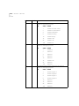
CONTENTS
ABOUT THIS GUIDE
Introduction ........................................................................................ 1
Finding Specific Information in This Guide ............................................ 2
Conventions ........................................................................................ 2
Related Documentation ....................................................................... 3
Year 2000 Compliance ........................................................................ 3
1
CONNECTING TO YOUR ISP
Windows 95/98 ................................................................................ 1-1
What You Need ........................................................................... 1-1
Configuring Your modem with Plug and Play .............................. 1-1
Files Needed By Your modem ...................................................... 1-2
Installing the Latest Software ...................................................... 1-2
Accessing Your Internet Service Provider ...................................... 1-2
Windows NT 4.0 and Later ............................................................... 1-8
What you need ........................................................................... 1-9
Configuring Your modem ............................................................ 1-9
Setting up RAS ............................................................................ 1-9
Determining if TCP/IP is installed ............................................... 1-10
Installing TCP/IP ......................................................................... 1-10
Configuring a PPP connection ................................................... 1-10
Configuring a SLIP connection ................................................... 1-11
Troubleshooting RAS ................................................................. 1-12
Macintosh ...................................................................................... 1-12
Handshaking Cable ................................................................... 1-12
System Configuration ................................................................ 1-13
Accessing the Internet ............................................................... 1-13
Macintosh (230K) High Speed script installation ........................ 1-13
Installing the script .................................................................... 1-13
Configuring Open Transport PPP ............................................... 1-14
Selecting the correct TCP/IP settings .......................................... 1-15
Setting up your ISP information .................................................1-16
Other Operating Systems ................................................................1-17
If You Are Using Windows 3.x ...................................................1-17
If You Are Using MS-DOS ...........................................................1-17
If You Are Using UNIX, Linux, or AIX ..........................................1-17
2
USING THE AT COMMAND SET
Overview ..........................................................................................2-1
General rules for using AT commands ..........................................2-1
Basic AT commands .........................................................................2-2
Using S-Registers ..............................................................................2-2
Displaying S-Register settings .......................................................2-3
Setting an S-Register ....................................................................2-3
Getting a list of S-Registers ..........................................................2-4
Understanding bit-mapped S-Registers ..............................................2-4
3
MODES OF OPERATION
Command and Online Modes ...........................................................3-1
Entering Online Command Mode ................................................3-2
Returning to Online Mode ...........................................................3-2
Controlling Local Echo ......................................................................3-3
Command-Mode Local Echo ........................................................3-3
Online-Mode Local Echo ..............................................................3-3
Data and Fax Modes .........................................................................3-4
4
DIALING, ANSWERING, AND HANGING UP
Dialing ..............................................................................................4-1
Dial options .................................................................................4-1
Carrier Loss Redial .............................................................................4-3
Answering Calls ................................................................................4-4
Force Answer Mode .....................................................................4-4
Auto Answer ...............................................................................4-4
Hanging up .................................................................................4-5
Making International calls .................................................................4-5
Handshaking options ...................................................................4-5
Guard tone ..................................................................................4-6
Call Detection .................................................................................. 4-6
Caller ID Functions ........................................................................... 4-7
Service Types ............................................................................... 4-7
Applications of Caller ID Technology ............................................ 4-7
How the Business Modem Handles Caller ID ................................ 4-8
Presentation Formats ................................................................... 4-9
Commands ................................................................................. 4-9
References ................................................................................ 4-10
Distinctive Ring Support ................................................................. 4-10
Commands ............................................................................... 4-11
Result Codes ............................................................................. 4-12
5
WORKING WITH MEMORY
Overview .......................................................................................... 5-1
Working with RAM and NVRAM ................................................. 5-2
Saving a Phone Number to NVRAM .................................................. 5-2
Displaying S-Register Value Information ....................................... 5-3
Saving a Command String to NVRAM ......................................... 5-3
Working with Flash Memory ............................................................. 5-3
Saving ROM Templates to NVRAM .............................................. 5-4
Default Settings ................................................................................ 5-4
6
CONTROLLING RESULT CODE DISPLAYS
Result Code Display Commands ....................................................... 6-1
Additional Result Code Subsets ........................................................ 6-2
7
CONTROLLING EIA-232 SIGNALING
Data Terminal Ready ......................................................................... 7-1
Data Set Ready ................................................................................. 7-2
Carrier Detect ................................................................................... 7-3
8
CONTROLLING DATA RATES
Overview .......................................................................................... 8-1
Serial Port Rates ............................................................................... 8-1
Connection Rates ............................................................................. 8-3
Controlling Link Speeds with &N and &U ..........................................8-4
Controlling Link Speeds ...............................................................8-4
Limiting the Highest Possible Connect Speed ...............................8-4
Limiting the Lowest Possible Connect Speed ................................8-5
Limiting a Range of Possible Connect Speeds ...............................8-5
&N and &U Command Values ......................................................8-6
Setting DTE Rate to 230 Kbps ...........................................................8-7
9
ACCESSING AND CONFIGURING THE BUSINESS MODEM
REMOTELY
Overview ..........................................................................................9-1
Setting Up Remote Access ................................................................9-1
At the Host Business Modem .......................................................9-1
Other Remote-Access Commands ................................................9-3
Accessing the Host ............................................................................9-3
At the Guest Device .....................................................................9-3
Viewing and Changing the Host’s Configuration ..........................9-4
Remote Configuration Commands ...............................................9-5
Quitting a Remote-Access Session .....................................................9-7
10
DIAL SECURITY
Overview ........................................................................................10-1
Setting up Dial Security ...................................................................10-2
Dialback options ........................................................................10-3
Modifying Accounts ...................................................................10-4
Autopass Prompting ..................................................................10-5
Password Prompting ..................................................................10-5
Maintaining Security Accounts ........................................................10-7
Remote Configuration ...............................................................10-7
What the Guest User Needs to Do ..................................................10-8
Configuring Dial Security Remotely .................................................10-9
11
FLOW CONTROL
Overview ........................................................................................11-1
Hardware and Software Flow Control .............................................11-2
Hardware Flow Control ..............................................................11-2
Software Flow Control .............................................................. 11-2
Received Data Flow Control ............................................................ 11-3
Transmit-Data Flow Control ............................................................ 11-5
12
HANDSHAKING, ERROR CONTROL, DATA COMPRESSION, AND
THROUGHPUT
Handshaking .................................................................................. 12-1
Selective Reject ......................................................................... 12-1
V.34 .......................................................................................... 12-3
V.90 Capabilities ............................................................................. 12-3
Other Protocols .............................................................................. 12-3
x2 ............................................................................................. 12-3
Fast Class (V.FC) Handshaking ................................................... 12-3
HST ........................................................................................... 12-4
USR V.32terbo to USR V.32terbo ............................................... 12-4
Lower-speed V. Protocols ........................................................... 12-5
Error Control .................................................................................. 12-5
Error-Control Commands .......................................................... 12-5
V.42 Error Control ..................................................................... 12-7
MNP Error Control ..................................................................... 12-7
Error Control and Flow Control ................................................. 12-7
Data Compression .......................................................................... 12-8
V.42bis versus MNP5 Data Compression .................................... 12-8
Getting Maximum Throughput ....................................................... 12-9
Maximum throughput results when: ............................................... 12-9
13
DISPLAYING QUERYING AND HELP SCREENS
Overview ........................................................................................ 13-1
Querying ........................................................................................ 13-1
Displaying Help .............................................................................. 13-3
14
TESTING THE CONNECTION
Overview ........................................................................................ 14-1
Testing the Business Modem using AT&Tn ...................................... 14-2
Analog Loopback Testing .......................................................... 14-3
Stopping a Test (AT&T0, ATS18) ................................................ 14-3
Digital Loopback Testing (AT&T3) ...............................................14-5
Remote Digital Loopback Testing (AT&T6, AT&T7) ......................14-6
Granting a Digital Loopback Test Request (AT&T4) .....................14-6
Canceling All Digital Loopback Test Requests (&T5) ....................14-6
Testing Using Keyboard Data (AT&T6) ........................................14-7
Testing Using a Built-in Test Pattern (AT&T7) ...............................14-8
Testing the Business Modem using S-Resister 16 .............................14-9
Analog Loopback (AL) S16=1D ..................................................14-9
Testing Using Keyboard Data (ATS16=8) ..................................14-10
Testing Using a Built-in Test Pattern (ATS16=4) .........................14-11
Ending Testing That Uses the Test Pattern ......................................14-11
15
TROUBLESHOOTING
Problems That Occur Before Connecting .........................................15-1
No response to AT .....................................................................15-1
The Business Modem won't dial .................................................15-2
Double characters are appearing on your monitor ......................15-3
After you dial, the Business Modem reports NO CARRIER and then hangs up
15-3
Hear ringing but the Business Modem won't answer .................15-3
The Business Modem acts as though a data link has been established, but
no call was received, ..................................................................15-3
The Business Modem behaves as if <Enter> were pressed when you don't
press any keys ............................................................................15-3
Problems that Occur After Connecting ...........................................15-4
Your screen displays random or "garbage" characters ...............15-4
Many CRC errors .......................................................................15-4
Mainframe computer keeps dropping your connection ..............15-5
Bad faxes or can't fax ................................................................15-5
Both devices exchange carrier signals, but fail to establish a
communications link ..................................................................15-5
Errors during software download ...............................................15-6
If You Still Have Problems ...............................................................15-6
16
UPGRADING YOUR MODEM
Overview ........................................................................................16-1
Checking Your Business Modem’s Software Version ........................16-1
Getting New Operating Software .................................................. 16-2
Sending New Software to your modem .......................................... 16-2
If Your Modem Doesn’t Respond .................................................... 16-4
A
S-REGISTERS
Understanding Bit-Mapped S-Registers .............................................A-1
How bits are mapped to decimal values ............................................A-1
Converting Bits to Decimal Values ....................................................A-2
Converting Decimal Values to Bits ....................................................A-2
Setting Bit-Mapped S-Registers .........................................................A-2
Using Bits .........................................................................................A-3
Using Decimal Values .......................................................................A-3
Default S-Register Settings ...............................................................A-3
A complete list of S-Registers ...........................................................A-5
B
ALPHABETIC COMMAND SUMMARY
Basic Command Set ......................................................................... B-1
Ampersand (&) Command Set .......................................................... B-5
Percent (%) Command Set ............................................................. B-11
Octothorpe (#) Command Set ........................................................ B-13
C
FLOW CONTROL TEMPLATE
Hardware Flow Control ....................................................................C-1
Software Flow control ......................................................................C-3
No Flow Control ...............................................................................C-4
D
RESULT CODE MEANINGS AND SETS
Result Code Meanings ......................................................................D-1
Result Codes Sets for Xn Values ........................................................D-2
E
TECHNICAL INFORMATION
Technical Specifications .................................................................... E-1
Modulation ................................................................................. E-1
Error Control, Data Compression, Testing, and Dialing ................. E-2
Fax .............................................................................................. E-2
Additional Specifications .............................................................. E-3
Serial Ports ................................................................................... E-3
The EIA-232 Interface .................................................................. E-4
Wiring a DB-25 to DB-9 Cable ..................................................... E-4
Minimum Requirements ............................................................... E-4
Flow Control Requirements .......................................................... E-5
For Macintosh Computers ......................................................... E-5
Serial Ports (Macintosh modem) ........................................................ E-6
F
ASCII CHART
G
FAX INFORMATION FOR PROGRAMMERS
Fax Service Class 1 Commands ......................................................... G-1
FAX Service Class 2.0 Commands ..................................................... G-1
Fax Mode Flow Control Setting ........................................................ G-2
FCC Notice ...................................................................................... G-2
Notes ............................................................................................... G-2
H
I
VIEWING LEDS
S-REGISTERS
S-Registers ......................................................................................... I-1
J
WARRANTY
3Com Corporation Limited Warranty .................................................J-1
Notices ..............................................................................................J-4
FCC Certification Statement .........................................................J-4
FCC Registration ................................................................................J-4
FCC Notice ........................................................................................J-4
FCC Notice: Radio and Television Interference ....................................J-5
IC (Industry Canada) .....................................................................J-6
UL Listed Accessory ............................................................................J-6
GLOSSARY
ABOUT THIS GUIDE
Introduction
This guide is a command reference for the 3Com OfficeConnect 56K
Business Modem. It includes information about AT commands,
S-Registers and troubleshooting.
If the information in the release notes shipped with your product differs
from the information in this guide, follow the instructions in the release
notes.
Finding Specific
Information in
This Guide
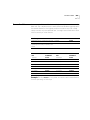
This table shows the location of specific information in this guide.
If you are looking for information about
Turn to
Connecting to your ISP
Chapter 1
Upgrading Your Busniess Modem
Chapter 3
Basic AT Commands
Chapter 2
Display Querying and Help Screens
Chapter 14
Testing a Connection
Chapter 15
Troubleshooting
Chapter 17
S-Registers
Appendix A
Alphabetic Command Summary
Appendix B
2
ABOUT THIS GUIDE
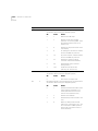
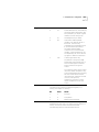
Conventions
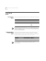
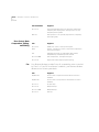
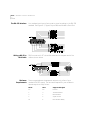
Table 1 and Table 2 list conventions that are used throughout this guide.
Table 1 Notice Icons
Icon
Notice Type
Description
Information note
Important features or instructions
Caution
Information to alert you to potential damage to a
program, system, or device
Warning
Information to alert you to potential personal injury
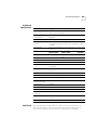
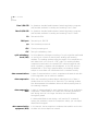
Table 2 Text Conventions
Convention
Description
Commands
The word “command” means you must enter the command
exactly as shown in text and press the Return or Enter key.
You may also be asked to fill in values for variables. Example:
wait n seconds between losing the connection and
redialing:
ATS44=n
This guide always gives the full form of a command in
uppercase and lowercase letters. However, you can
abbreviate commands by entering only the uppercase letters
and the appropriate value. Commands are not case-sensitive.
Screen displays This typeface represents information as it appears on the
screen.
The words “enter”
and “type”
When you see the word “enter” in this guide, you must type
something, and then press the Return or Enter key. Do not
press the Return or Enter key when an instruction simply says
“type.”
(continued)
[Key] names
Key names appear in text in one of two ways:
■
■
Referred to by their labels, such as “the Return key” or
“the Escape key”
Written with brackets, such as [Return] or [Esc].
If you must press two or more keys simultaneously, the key
names are linked with a plus sign (+). Example:
Press [Ctrl]+[Alt]+[Del].
Menu commands
and buttons
Menu commands or button names appear in italics. Example:
From the Help menu, select Contents.
Related Documentation
3
Table 2 Text Conventions (continued)
Convention
Description
Words in italicized
type
Italics emphasize a point or denote new terms at the place
where they are defined in the text.
Words in bold-face
type
Bold text denotes key features.
Related
Documentation
The 3Com OfficeConnect 56K Business Modem Installation Guide should
be used for the installation of the Business Modem.
Year 2000
Compliance
For information on Year 2000 compliance and 3Com products, visit the
3Com Year 2000 web page:
http://www.3com.com/products/yr2000.html
4
ABOUT THIS GUIDE
1
CONNECTING TO YOUR ISP
This chapter contains information about configuring your modem for
various operating systems.
Windows 95/98
■
Windows 95/98
■
Windows NT 4.0 and Later
■
Macintosh
■
Other Operating Systems
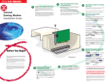
The first time you start Windows 95/98 after you’ve installed the modem,
Windows 95/98 will auto-detect your modem. Since Windows 95/98
supports Plug and Play, most installations are trouble-free.
You must power on your modem before you start Windows 95/98, or
Windows 95/98 will not recognize your modem.
What You Need
Configuring Your
modem with Plug
and Play
You need Windows 95/98 with Dial-Up Networking installed to configure
your modem for Windows 95/98.
Plug and Play mode allows Windows 95/98 to automatically detect your
modem and determine which modem configuration file (called an INF
file) to use.
Follow the steps below to install the INF file for Windows 95/98:
1 Power on your computer and start Windows 95/98. Your computer will
detect new hardware.
2 When the New Hardware Found window appears, select Driver from
disk provided by hardware manufacturer and click OK.
This step will install the INF file that is provided on the Connections
CD-ROM.
1-2
CHAPTER 1: CONNECTING TO YOUR ISP
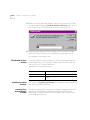
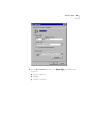
3 When the following window appears, insert your Connections CD-ROM,
change the default drive in Copy Manufacturer’s files from: to D:\ (or the
correct path of your CD-ROM) and click OK to install the INF file.
4 Windows 95/98 displays a window asking you to choose your modem
type from the list. Select the your modem from the list and click OK.
Your modem is now ready to use!
Files Needed By Your
modem
For your modem to work most efficiently, 3Com recommends that you
use the latest version of the modem software and information (INF) file
from the 3Com U.S. Robotics Web site
(http://www.usr.com/home/online/).
This file
Does this
The modem software
Contains software that contains new feature updates
The INF file
Helps your computer work more effectively with your
modem
Installing the Latest
Software
See Chapter 3, Upgrading your Modem for information about upgrading
your Business Modem’s software.
Accessing Your
Internet Service
Provider
This section explains how to set up your modem to access the Internet or
remote Local Area Networks (LANs) using Windows 95/98 Dial-Up
Networking. To Access Internet Service Providers (ISPs) or remote LANs
you must do the following:
Windows 95/98
1-3
Step One: Determine if Dial-Up Networking is Installed
1 Click Start | Settings | Control Panel.
2 On the Control Panel, double-click on Network. The Network widow will
appear.
If Dial-Up Adapter Do this
Is listed
Go to the section "Installing TCP/IP Support" to install Dial-Up
Networking.
Is not listed
Go to Step 3.
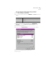
3 Return to the Control Panel and double-click on Add/Remove
Programs to open the Add/Remove Programs Properties window.
4 Click Windows Setup tab.
5 Double-click on Communications. The following window appears:
6 Click on Dial-Up Networking to check the box.
7 Click OK | OK.
1-4
CHAPTER 1: CONNECTING TO YOUR ISP
8 Insert your Windows 95/98 Setup diskette or CD-ROM when you are
prompted, and Windows 95/98 installs Dial-Up Networking.
Step Two: Installing Dial-Up TCP/IP Support
1 Click Start | Settings | Control Panel.
2 On the Control Panel, double-click on the Network to display the
Network window:
3 Determine if the TCP/IP Dial-Up Adapter is installed:
IF TCP/IP -> Dial-Up Adapter
Do this
Is not listed
Click Add | Protocol | Microsoft | TCP/IP | OK.
Insert your Windows 95/98 Setup diskette or
CD-ROM when you are prompted, and Windows
95/98 installs TCP/IP protocol support.
Is listed
Go to Step 3.
Step Three: Setting Up a Connection to Your ISP
1 Click Start | Programs | Accessories | Dial-Up Networking.
2 Double-click Make New Connection.
3 Select the correct modem, if not already selected.
4 Type a name for the connection and click Next.
5 Type a phone number for the connection and click Next.
6 You should see a message indicating that a new connection was created
successfully.
7 Click Finish.
8 A New Connection icon will be created in the Dial-Up Networking
Window. Move your cursor to the new icon you have just created and
click the right mouse button. Select Properties on the menu to display the
following window:
The following screen may vary slightly depending on the version of
Windows 95/98 you are using.
Windows 95/98
1-5
9 On the My Connection window, click Server Type, and deselect the
following:
■
Log on to Network
■
NetBEUI
■
IPX/SPX Compatible
1-6
CHAPTER 1: CONNECTING TO YOUR ISP
10 Click OK, and OK.
If your ISP
Do this
Gives you a specific IP
or Domain Name
server addresses
Go to Step Four: Customizing TCP/IP Settings
Does not give you a
Double-click on the icon you just created to dial your ISP.
specific IP or Domain
Name server addresses
Step Four: Customizing the TCP/IP Settings
Depending on the ISP you use, you may need to customize the TCP/IP
settings. Follow steps 1-6 and if you still cannot connect to your ISP
contact you can contact your ISP for specific information such as an IP
address or Domain Name Servers (DNS).
1 Double-click My Computer and double-click Dial-Up Networking to
display all the connections you can customize.
2 Right-click the icon you created and select Properties to display the My
Connection properties window.
3 On the My Connection properties window, click the Server Type tab.
4 Click TCP/IP Settings
Windows 95/98
1-7
5 Specify an IP address, if needed:
If your ISP
Do this
Gives you a specific IP
address
Click Specify an IP address and enter the IP address
provided by your ISP
Does not give you a
specific IP address
Click Server assigned IP address
6 After you specify an IP Address, specify server assigned name server
addresses, if needed:
If your ISP
Do this
Gives you specific name
server addresses
Click Specify name server addresses and enter the
server address(es) provided by your ISP
Does not give you
specific name server
addresses
Click Server assigned server address
1-8
CHAPTER 1: CONNECTING TO YOUR ISP
7 Double-click your New Connection icon to connect!
Windows NT 4.0
and Later
TCP/IP is the main protocol used to transfer data via the Internet. To use
TCP/IP with Windows NT, you must connect to your ISP using a PPP or
SLIP connection.
Each ISP has different requirements. Before using this chapter to
configure Windows NT to access your ISP, contact your ISP to determine if
they have special instructions for Windows NT users.
For you to
Use this connection
Use a dial-up connection to connect over the
Internet.
Serial Line Internet Protocol (SLIP)
SLIP only allows you to connect using IP and
does not allow for server assigned IP addresses
or server assign name server addresses.
Use a dial-up connection to connect over the
Internet.
Point-to-Point Protocol (PPP)
PPP allows you to connect using IPX, TCP/IP,
Netbeui, and other protocols. PPP is a more
recent development than SLIP and has
become the standard way of connecting to
the Internet.
CAUTION: Before you use these procedures, contact your ISP to
determine if they have any special requirements.
Windows NT 4.0 and Later
What you need
Configuring Your
modem
1-9
Before you begin, obtain the following information:
■
Does your ISP have a SLIP or PPP account?
■
Your ISP’s telephone number
■
Does your ISP supply a static or dynamic IP address?
■
Your ISP's primary and secondary DNS servers
■
INF file for Windows NT
Since Windows NT is not Plug and Play compliant, it is necessary to install
the modem in Modem Properties.
Your modem should already be installed. If you have not connected your
Business Modem to your computer, please refer to the Getting Started
Manual for installation instructions.
1 Go to Start | Settings | Control Panel | Modems
2 Click Add
3 Check Don’t detect my modem; I will select it from a list
4 Click Next
5 Click Have Disk.
6 Place the diskette or CD-ROM that was packaged with your Business
Modem into your floppy disk or CD-ROM drive. Select the INF file found
on the disk.
7 Select the COM port for your Business Modem.
8 When the installation is complete, Windows NT will request that you
restart your computer. Select yes.
Setting up RAS
1 Right click on the Network Neighborhood icon on your desktop and
select Properties.
2 Click the Services tab.
3 Select Remote Access Service and click Properties.
4 Click Add.
5 Select your Business Modem’s COM port and click OK.
6 Highlight your Business Modem and click Configure.
7 Select the function of your modem and click OK.
1-10
CHAPTER 1: CONNECTING TO YOUR ISP
8 Click Network.
9 Select the protocols required to dial in and out with your Business
Modem.
10 Set Encryption Settings to Allow any authentication including clear
text.
11 Click Continue to complete RAS setup.
Determining if TCP/IP
is installed
TCP/IP must be installed before you can access the Internet. Although this
is a standard configuration, double-check to make sure TCP/IP is installed.
To determine if TCP/IP is installed, perform the following actions:
1 Select Start | Settings | Control Panel
2 Double-click Network
3 On the Protocol tab, scan down the list of installed protocols to find
TCP/IP Protocol Adapter.
4 If TCP/IP Protocol is listed, skip to section Configuring a PPP Connection.
If TCP/IP Protocol is NOT listed move to the next section.
Installing TCP/IP
To install TCP/IP, perform the following actions:
1 Select Start | Settings | Control Panel
2 Double-click Network
3 On the Protocol tab, click Add, and select the TCP/IP protocol from the
list.
Configuring a PPP
connection
To configure the Business Modem for a PPP connection, perform the
following actions:
1 Go to Start | Programs | Accessories | Dial Up Networking
2 Click New.
3 Select the Server tab and select PPP in the Dial-up server type box.
4 Select TCP/IP
5 Deselect NetBEUI and IPX.
6 If you are connecting to an ISP, uncheck Enable PPP LCP Extensions
If you are connecting to another Windows NT system, Check Enable PPP
LCP Extensions
Windows NT 4.0 and Later
1-11
7 Select Enable software compression.
8 Specify an IP address by clicking TCP/IP settings.
If your ISP
Do this
Gives you a specific IP address
Click Specify an IP address and enter
the IP address provided by your ISP
Does not give you a specific IP address
Click Server assigned IP address
9 After you specify an IP Address, specify server assigned name server
addresses, if needed
:
If your ISP
Do this
Gives you specific name server
addresses
Click Specify name server addresses and
enter the server address(es) provided by your
ISP
Does not give you specific name Click Server assigned server addresses
server addresses
Configuring a SLIP
connection
The following steps explain how to configure Windows NT for use with a
SLIP connection.
1 Double-click Dial-Up Networking.
2 Click New
3 Select the Server tab and select SLIP in the Dial-up server type box.
4 Click TCP/IP settings.
5 Enter the IP address provided by your ISP.
6 Enter the primary DNS and secondary DNS server IP addresses in the
appropriate name server address boxes.
7 If your ISP requests that you use a specific frame size, select the desired
frame size in the Frame Size box.
1-12
CHAPTER 1: CONNECTING TO YOUR ISP
Troubleshooting RAS
RAS is significantly easier to troubleshoot then Win95 Dial-Up
Networking, there are a finite number of problems that one runs into on
a daily basis, and the majority of these are caused by misconfiguration.
Most connection problems can be solved by following these steps:
■
In the Basic tab, Make sure that the phone book entry settings are
correct.
■
Make sure Use Telephony Dialing Properties is unchecked
■
Make sure to that Use another port if busy is not checked.
■
In the phone book settings, under security, it should be set to: Accept
any authentication including clear text.
■
Make sure only the necessary network protocols are selected.
■
■
In the Connect to window, after you click Dial, there should be no
domain set. This is only for logging into NT domains.
Make sure that the TCP/IP settings are correct.
This is a general setup for your Business Modem using Windows NT. If
you are having problems connecting to you ISP, configuring Dial-Up
Networking, or receiving RAS errors, please contact Microsoft Technical
support.
Macintosh
This section explains how to configure your modem for use with
Macintosh computers.
There are many ways to configure your Macintosh to use the Internet.
Consult your Macintosh documentation for more information.
Handshaking Cable
Use a hardware handshaking cable to connect your modem to the
Macintosh.
Macintosh
System Configuration
1-13
Also, if you aren’t using AppleTalk® Remote Access (ARA), set AppleTalk
to Inactive (in Chooser).
The modem initialization string should be AT&F1&D0.
For instructions about how to set up your Macintosh communications
software package, see the software installation instructions that came
with the software.
Accessing the
Internet
Accessing the Internet through an ISP requires the following software:
■
MacTCP or Open Transport (TCP/IP from the Control Panels menu),
which has probably already been installed on your Macintosh
■
SLIP or PPP dialing software
You can find public domain PPP dialers (such as MacPPP, FreePPP) on the
Internet.
Macintosh (230K)
High Speed script
installation
To enable the 230K DTE support for the Business Modem and 25 mhz
Business Modem you first must install the Macintosh (230K) High Speed
Script and then configure Open Transport PPP.
Installing the script
1 Download the USRARA.HQX file.
This file can be found on the internet at
http://www.usr.com/home/online/ in the software library area. It can also
be downloaded from the BBS at 847-262-6000.
2 After the file is downloaded, it needs to uncompressed. When the file is
uncompressed the USRARA.SEA Folder appears.
3 Inside the USRARA.SEA folder is a readmefirst.txt file and the 3Com High
Speed script.
4 Move the script file to the following path C:\System\Extensions\ and
create a folder named Modem Scripts.
Once you place the script in the Modem Scripts folder you will have the
option to choose the 3Com High Speed in Open Transport PPP or ARA.
The script will attempt to talk to the modem at 230.4 port speed and if
this fails, it will attempt at the next lowest speed. This will continue until
1-14
CHAPTER 1: CONNECTING TO YOUR ISP
the script receives an OK back from the modem and/or the system
responds with a proper speed.
Configuring Open
Transport PPP
Selecting the correct modem
1 Go to Apple Menu | Control Panels | Modem.
2 In the Modems Window, choose the port that your modem is connected
to in the Connect via drop down box.
3 Select the correct modem, in the Modem drop down box.
Macintosh
1-15
Selecting the correct
TCP/IP settings
1 Go to Apple Menu | Control Panel | TCP/IP.
2 In the TCP/IP window, select PPP in the Connect via drop down box.
3 Set the Configure drop down box to Using PPP Server.
4 Type in your internet service providers Domain Name Server Address(DNS)
numbers in the Name server addr box.
5 Leave the other fields empty.
1-16
CHAPTER 1: CONNECTING TO YOUR ISP
Setting up your ISP
information
1 Go to Apple Menu | Control Panels | PPP.
2 In the PPP window, select Registered User.
3 Type in your Internet Service providers login name and your password in
the name and password boxes.
4 Put the phone number that you dial to connect to your internet provider
in the number box.
You’ve successfully configured Open Transport PPP!
Other Operating Systems
Other Operating
Systems
If You Are Using
Windows 3.x
1-17
This sections explains how to configure your modem for:
■
Windows 3.x
■
MS-DOS
■
UNIX, Linux, or AIX
Windows 3.x comes with a built-in communications software package,
Windows Terminal. You can use Windows Terminal to test your modem
or you can install the communications software package that is included
on the Connections CD-ROM.
Because Windows Terminal only supports speeds up to 19200 bps, it is
recommended that you use a third-party communications software
package.
If You Are Using
MS-DOS
Because there is no communications software built in to MS-DOS, you
must install and run a third-party communications software package to
operate your modem.
RapidComm, which is included on the Connections CD-ROM, contains
MS-DOS and Windows 3.1 versions of RapidComm.
You must choose the COM port to which your modem is attached in
whatever communications software package you are using.
If You Are Using
UNIX, Linux, or AIX
For instructions about how to set up your UNIX®, Linux, or AIX
communications software package, see the software’s installation
procedure.
1-18
CHAPTER 1: CONNECTING TO YOUR ISP
2
USING THE AT COMMAND SET
This chapter includes information about
Overview
■
Basic AT commands
■
Using S-Registers
■
Understanding bit-mapped S-Registers
You can use AT commands to change your modem settings at any time.
To send AT commands to your modem, you need to put your
communications software in Terminal Mode. In terminal mode, what you
type is sent directly to the modem.
General rules for
using AT commands
You must follow some general guidelines to send AT commands to your
modem:
■
Type AT before each command and press <ENTER> after each
command.
The exceptions are A/, A> and +++, which require neither AT nor
<ENTER>.
■
Leave zeroes off the end of AT commands. A missing numeric
parameter is assumed to be a zero. For example, ATE is equivalent to
ATE0.
■
Create compound commands of up to 56 characters between AT and
<ENTER>. See the following example.
2-2
CHAPTER 2: USING THE AT COMMAND SET
AT&K3X2DT5551234
AT
Attention; a command follows.
&K3
Disable MNP5 data compression; use only V.42 bis compression.
X2
Use the X2 result code subset.
DT
Dial the following number using tone dialing.
Hyphens and parentheses add to the count of 56 characters but, spaces
do not.
Basic AT commands
The command AT informs the modem that a command is coming. AT
must precede all commands except A/, A> and +++.
To configure your modem to
Command
Re-execute the last-issued command.
A/
Repeat the last-issued command until canceled by pressing
any key.
A>
Example: Sending ATD5551234 will make the modem dial 555-1234.
Now, if you send A/ the modem will dial 555-1234 again.
Using S-Registers
S-Registers are addresses of places in memory where various timing
parameters, redefinitions of selected ASCII characters, and other
configuration settings are stored.
Initially, the S-Register settings for each of the NVRAM templates are the
same. You can overwrite an S-Register’s stored value. See the default
values listed in Appendix A, S-Registers, for a complete listing of the
initial settings.
Using S-Registers
Displaying S-Register
settings
2-3
You can display S-Registers in a variety of ways. See the table below for
more information.
To display
Command
Contents of ONE S-Register
ATSr?, where r is the
register’s number
S-Register settings in the NVRAM templates
ATI5
S-Register settings in RAM (the current configuration)
ATI4
Example: Sending ATS0?, displays the contents or setting for S-Register
0.
When using the commands ATI4 and ATI5, S-Register settings appear as a
table seven columns wide, each entry of the form, "Smm=nnn" where
mm is a register number between 0 and 70 and nnn is a decimal value
between 0 and 255.
Setting an S-Register
You can configure each S-Register setting manually.
CAUTION: If you do not write an S-Register setting with &W, the setting
will be retained only until the next reset or power off.
To change
Settings for a register in the current configuration
Command
ATSr=n
Example: Sending ATS0=2, changes the setting for S-Register 0 to 2. This
setting will cause the Business Modem to answer, in Auto Answer Mode,
on the second ring.
In the command ATSr=n, r is the register's number and n is a decimal
value from 0-255 (unless otherwise indicated) that specifies the setting.
2-4
CHAPTER 2: USING THE AT COMMAND SET
Getting a list of
S-Registers
To display
Command
A list of S-Registers
ATS$
In order to issue this command, you must be in Terminal Mode.
See Appendix A, S-Registers for a complete list of S-Registers.
Understanding
bit-mapped
S-Registers
A bit-mapped S-Register uses one number to describe a collection of
settings. Bit-mapping allows us to pack a lot of information in a small
space.
Bit-mapped registers are in the form of Sr.b=n, where r is the bit-mapped
register; .b is the bit; n is 0 (off) or 1 (on).
See Appendix A, S-Registers to see how bits are mapped into decimal
values and for information about setting bit-mapped S-Registers.
3
MODES OF OPERATION
This chapter contains information about
Command and
Online Modes
■
Command and Online Modes
■
Controlling Local Echo
■
Data and Fax Modes
If you want to
Set the modem to
Use this command
Control the modem using AT Command Mode
commands.
+++ (Escape Code)
Your modem set to revert to
Command Mode when the
Escape Code (+++) is used.
ATS14.0=0
Your modem to Disconnect
when the Escape Code (+++)
is used.
ATS14.0=1
Return to your connection
after an Online Command
Mode session.
Online Mode
ATO0
Send the modem commands
while you are on line with
another device.
Online Command
Mode
+++ (Escape Code)
DO NOT type AT before +++ or <ENTER> after the command
3-2
CHAPTER 3: MODES OF OPERATION
Entering Online
Command Mode
When the modem is in Online Mode, the only command it recognizes is
an escape code, or +++.
Revert to Command Mode without losing connections by sending
ATS14.0=0 to the modem before establishing your connection.
5 Wait one second after sending the last item of data
6 Type +++
7 Wait for OK to appear before typing any data
You can change the characters used to revert to Command Mode or the
wait time by resetting Register S2 or S12. For more information about
resetting these S-Registers, see Appendix A, S-Registers.
Returning to Online
Mode
There are two ways to return online using the ATOn command.
.
If you want to
Command
Return online
ATO0
Return online and retrain
ATO1
Example: Sending ATO1, will allow you to resynchronize if you
experienced errors during a non-ARQ data transfer.
Controlling Local Echo
Controlling Local
Echo
Command-Mode
Local Echo
3-3
There are two local echo settings, one for Command Mode and one for
Online Mode.
You can configure your modem to display the commands you type on
screen by using the ATEn command
.
If you want the commands you type to
Command
NOT appear on screen (Command Mode echo OFF)
ATE0
Appear on your screen (Command Mode echo ON)
ATE1
Although you cannot see the command when you set ATE0, the modem
is receiving them.
Online-Mode Local
Echo
To configure your modem to display a copy of data that is being
transmitted on your screen you can use the ATFn command.
As the modem transmits data to a remote system
Command
The modem sends a copy of the data to the screen. Online
local echo ON (“half duplex”).
ATF0
No copy of the data is displayed on screen. Online echo OFF ATF1 (default)
(“full duplex”).
Example: Sending ATF0 will allow you to see what you are typing in the
display window.
You may see the term duplex used in place of online local echoing,
although the term is not technically accurate.
3-4
CHAPTER 3: MODES OF OPERATION
Data and Fax
Modes
Once you are in Command Mode, you can initialize the modem in Data
or Fax mode.
Fax operations require facsimile-compatible communications software
that can send or receive Group III faxes. Follow the instructions in your fax
software manual.
The modems default operating mode is Data Mode. Most fax software
automatically switches the device to Fax mode when you run the
program, and resets the device to Data mode when you exit the program
.
If you want the modem prepared to
Mode
Command
Make calls to and receive calls from other
modems
Data Mode
AT+FCLASS=0
Make calls to and receive calls from analog
facsimile devices, such as fax modems and
fax machines
Fax Mode
AT+FCLASS=1
(Class 1 Fax Mode)
or
AT+FCLASS=2.0
(Class 2.0 Fax
Mode)
Example: Sending AT+FCLASS=1, allows you to receive faxes from fax
machines.
Class 1 and Class 2.0 Fax Modes refer to standards set by the Electronic
Industries Association/Telecommunications Industry Association. Class 1
Fax Mode is the minimal standard for computer-faxmodem interface.
Class 2.0 Fax Mode refers to the extended computer-faxmodem interface.
Data and Fax Modes
3-5
If you are not sure whether your modem is in Data or Fax mode, use the
AT+FCLASS? command
.
If the modem
returns a value of
This indicates
0
Data Mode
1
Class 1 Fax Mode
2.0
Class 2.0 Fax Mode.
Whenever the modem is reset using the ATZ command or by turning the
power off and then on, it will reset to Data Mode.
3-6
CHAPTER 3: MODES OF OPERATION
DIALING, ANSWERING, AND
HANGING UP
4
This chapter explains how to use basic AT commands for:
Dialing
■
Dialing
■
Carrier loss redial
■
Answering calls
■
Making International calls
■
Call detection
■
Caller ID functions
■
Distinctive Ring support
You can use your modem to dial the specified phone number and execute
dial options by using the following commands.
Dial options
For your modem to
Command
Dial the specified phone number and execute dial
options (DO NOT use spaces or dashes).
ATD phone number
Tone dial.
ATDT
Pulse dial.
ATDP
Pause for the length of time specified by S-Register 8.
The default is 2 seconds.
ATD, (Comma)
Pause for 125 milliseconds.
ATD/ (Slash)
Wait for a second dial tone before continuing dialing.
ATDW
This command only works only if the X3 (or higher)
command has been issued (see Chapter 7, Controlling
Result Code Displays and Appendix D, Result Code
Meanings and Sets). If the modem is set to X2 or lower,
it interprets the W as a two-second pause, unless it
detects a second dial tone within two seconds.
4-2
CHAPTER 4: DIALING, ANSWERING, AND HANGING UP
For your modem to
Command
Wait for an answer (with X3 or higher).
ATD@
Some online services answer the phone and return a
tape-recorded request for information before
processing transactions.
Use the AT@ command to tell the modem to detect at
least one ring, wait for five seconds of silence at the
other end of the call, and then continue.
To use the AT@ command, set the modem to X3, X4 or
X7.
If set X2 or lower, the modem will return an ERROR
message when it encounters the @ character. If set to
X5 or X6, the modem hangs up when it detects a voice
answer.
Return to Command mode after dialing.
ATD; (Semicolon)
Dial the letters that follow (in an alphabetical phone
number).
ATD"
If you are including another command after the phone number, use closing
quotation marks before the additional command.
IMPORTANT: With the exception of the above Dial options, your modem will
ignore any commands issued after the D in the same command string.
Call a device that can only originate calls. It forces the
modem to dial out at the answer frequency or Reverse
frequencies. You can put the R either before or after
the number.
ATDR
Display different sets of result codes. See Chapter 6,
Controlling Result Code Displays and Appendix D,
Result Code Meanings and Sets.
ATX2D..... X7D
Dial the last-dialed number. Use ATDL instead of using
A/ if you wish to send the modem non-Dial commands
before dialing again.
ATDL
Display the last-dialed number.
ATDL?
Dial the number stored in nonvolatile random access
memory at position n, where n = 0*9. See Chapter 6,
Working with Memory, for instructions about saving
phone numbers to memory.
ATDSn
Digits 0 through 9, * and # are accepted.
Stop dialing or stop repeating.
Type any key
Reissue the last command (Don’t type AT or press
<ENTER>).
A/
Carrier Loss Redial
For your modem to
Command
Dial a number, wait 60 seconds for a connection, and
then hang up. Wait two seconds, then redial. Make a
maximum of 10 attempts.
>
4-3
To stop the repeating, press any key during the pause
between dial attempts. If you press any key while the
modem is dialing, that dial attempt is canceled but the
cycle will continue
Dial the last-dialed number and repeat it just as the >
command does. Also can be used to repeat any
command.
Carrier Loss Redial
A>
You can set the Business Modem to redial the last-dialed number after it
loses carrier (carrier is the signal maintained between two modems while
they are on line). This feature is useful for dialed-line connections that
operate unattended.
For your modem to
Command
Disable carrier loss redial
ATS69.1=0
Enable carrier loss redial
ATS69.1=1
Wait n seconds between losing the connection and
redialing.
ATS44=n
This command also defines the interval (in seconds)
between dialing attempts in the that the first attempt is
not successful.
Example: Sending ATS44=20 sets a 20-second interval between losing
the connection and redialing.
4-4
CHAPTER 4: DIALING, ANSWERING, AND HANGING UP
Answering Calls
Your modem can be configured to answer calls. By default, your Business
Modem will not automatically answers calls.
Force Answer Mode
For your modem to
Command
Go through the answer sequence when it hasn't
received an incoming call
ATA
Or
Manually answer a call
Auto Answer
You can set your modem to Auto Answer using the ATS0 command
.
For your modem to
Command
Receive calls unattended (Auto answer enabled)
ATS0=1 (this instructs the
modem to answer on the
first ring)
Remember to set your communications software to
save incoming messages and/or files.
NOT receive calls unattended (Auto answer disabled) ATS0=0
Example: Sending ATS0=0 will not allow your modem to receive calls
when you are not present.
See the S-Register summary in Appendix A, S-Registers for more
information about instructing the modem to answer after more than 1
ring.
When your modem senses a call coming in, it sends the result code RING
to your computer, goes off hook, and negotiates for a connection. If
there is no response within 60 seconds, the Business Modem hangs up.
For more information about adjusting the 60-second wait-for-connection
time using S-Register 7, see Appendix A, S-Registers.
When a call is disconnected, the Business Modem hangs up and returns
the NO CARRIER result code.
If S0=0, Auto Answer is disabled. To determine if Auto Answer is NOT
disabled send the command ATI4 and be sure that S0=1-255.
Making International calls
Hanging up
4-5
If you want to end a connection with a remote device do the following:
1 Enter Online Command Mode by typing +++
2 Wait 1 second
3 Type ATH
Making
International calls
You can use the ATBn, AT&Gn and ATPn commands for making analog
international calls above 1200 bps.
Handshaking options
The ATBn command controls the handshake options.
.
If you want your modem
Command
To answer all V.34-type calls, as well as calls from overseas,
use ITU-T (formerly CCITT) answer sequence.
ATB0 (Default)
NOT to answer V.34-type calls. Use Bell answer tone. This
setting selects HST modulation.
ATB1
Example: Sending ATB1, will allow your modem to use Bell answer tone
(selecting HST modulation).
4-6
CHAPTER 4: DIALING, ANSWERING, AND HANGING UP
Guard tone
The AT&Gn command only applies to analog overseas calls at 2400 or
1200 bps.
To set your modem for
Command
Required in these countries
No guard tone
AT&G0
(Default)
United States and Canada
550-Hz guard tone
AT&G1
Some European countries
1800-Hz guard tone
AT&G2
The U.K. and some Commonwealth
countries
If you set &G2 you must also send ATB0 to the modem. This setting
allows the Business Modem to answer all calls from overseas.
Make/Break Ratio
The AT&Pn command sets the off-hook/on-hook (make/break) interval for
pulse dialing.
Call Detection
To set you modem for
Command
North American make/break ratio (39/61)
AT&P0
United Kingdom make/break ratio (33/67)
AT&P1
Call Detection allows the modem to recognize whether an incoming call
is analog data or fax.
Call Detection is an optional Service Class 2.0 feature and is also
implemented by 3Com for Fax Class 1 applications.
Caller ID Functions
Caller ID Functions
4-7
Caller ID is a service provided by local telephone companies. When you
subscribe to caller ID, your phone company begins providing you
real-time information about incoming calls.
The caller ID signal includes the date and time of the call, the phone
number of the calling device, and, optionally, the name of the calling
party. The signal is sent between the first and second rings and must be
decoded and displayed by a device connected to your phone line. The
Business Modem has the ability to decode and display the caller ID
information.
Service Types
You can subscribe to Basic or Extended caller ID service. Basic service
offers you the date and time of the call and the calling party’s telephone
number. Extended service provides the billing name associated with the
calling party’s telephone number in addition to the Basic service
information.
The information the Business Modem actually receives depends on the
service type to which you’ve subscribed, the information that the calling
party’s telephone company provides, and whether the equipment in
between supports caller ID. At minimum, you will always receive the date
and time that a call arrived.
If a call arrives without a caller ID signal, the modem will send OUT OF
AREA in place of the phone number and name. If the caller ID
information has been blocked by the user at the other end, the Business
Modem will send PRIVATE in place of the phone number and name.
Applications of Caller
ID Technology
You can use caller ID to screen calls, keep a record of calls, or prevent
unauthorized access to your network. Third-party database and
telephony applications such as security, call logging, and black-listing
applications exploit the caller ID information provided by the Business
Modem.
4-8
CHAPTER 4: DIALING, ANSWERING, AND HANGING UP
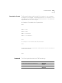
How the Business
Modem Handles
Caller ID
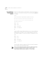
When the modem receives the caller ID signal, it stores the information in
memory. You can access the information at any time by sending ATI15 to
the modem.
ati15
3Com OfficeConnect 56K Business Modem CID Status…
80 1E 01 08 31 30 31 35 32 30 33 38 02 0A 37 30
38 35 35 35 30 30 30 31 07 0C 55 2E 53 2E 52 4F
42 4F 54 49 43 53 22
DATE = 1015
TIME = 2038
NMBR = 8475550001
NAME = U.S.ROBOTICS
OK
Using the #CID command (described below), you can have the Business
Modem send the information to your computer between the first and
second RING messages. The caller ID information is displayed only once.
RING
DATE = 1015
TIME = 2038
NMBR = 8475550001
NAME = U.S.ROBOTICS
RING
The information remains in memory until either you reset the modem or
until it receives another valid caller ID signal.
To be sure that the Business Modem receives the caller ID signal when
auto-answer is enabled, set S0=2 or higher or make sure your
communications software is set to answer on 2 or more rings.
Caller ID Functions
Presentation Formats
4-9
The Business Modem sends the caller ID information to your computer
formatted or unformatted. Formatted presentation is a translation of the
caller ID signal into ASCII text. Unformatted presentation is a hexadecimal
representation of the caller ID signal.
An Example of Formatted caller ID presentation:
RING
DATE = 1015
TIME = 2038
NMBR = 8475550001
NAME = U.S.ROBOTICS
RING
An Example of Unformatted caller ID presentation:
RING
801E01083130313532303338020A37303835353530303031070C552E532E
524F424F5449435322
RING
Commands
The following table describes the AT#CID=n settings.
Caller ID Action
Command
Disable Caller ID detection and reporting
AT#CID=0
(Default)
Enable Caller ID with formatted output
AT#CID=1
Enable Caller ID with unformatted output
AT#CID=2
4-10
CHAPTER 4: DIALING, ANSWERING, AND HANGING UP
Caller ID Action
Command
Enable Caller ID with formatted output and name AT#CID=3
suppressed
References
Enable Caller ID but do not transmit the
information to your computer—retain it in the
Business Modem’s memory
AT#CID=4
Display the current caller ID setting.
AT#CID?
Display the Caller ID settings that are available
AT#CID=?
For more information about Calling Number Delivery (CND), refer to
Bellcore documents TR-TSY-000030 and TR-TSY-000031. To obtain
Bellcore documents, contact:
Bellcore Customer Service
8 Corporate Place
Room 3A184
Piscataway, NJ 08854-4196
(800)521-2673
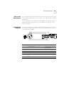
Distinctive Ring
Support
Distinctive ring is a service provided by local telephone companies that
permits the assignment of multiple phone numbers to one line. Each
phone number is associated with a different ring pattern, and devices
that recognize distinctive ring, like the Business Modem, can be set to
answer only on certain incoming ring patterns.
For example, a fax machine, answering machine, telephone, and modem
could all share the same line. Each device would have its own phone
number and respond only to calls intended for that number.
Distinctive Ring Support
4-11
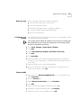
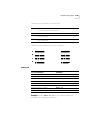
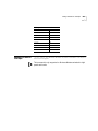
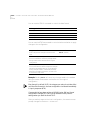
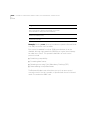
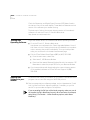
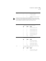
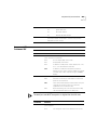
There are four ring patterns in common use:
Ring
Description
A
1.2 to 2.0 seconds on, 4.0 seconds off.
B
0.8 second on, 0.4 second off, 0.8 second on, 4.0 seconds off.
C
0.4 second on, 0.2 second off, 0.4 second on, 0.2 second off, 0.8 second
on, 4.0 seconds off.
D
0.3 second on, 0.2 second off, 1.0 second on, 0.2 second off, 0.3 second
on, 4.0 seconds off.
These are graphical depictions of each ring pattern.
Commands
For your modem to
Command
Enable recognition of Ring A
ATS70.0=1
Disable recognition of Ring A
ATS70.0=0
Enable recognition of Ring B
ATS70.1=1
Disable recognition of Ring B
ATS70.1=0
Enable recognition of Ring C
ATS70.2=1
Disable recognition of Ring C
ATS70.2=0
Enable recognition of Ring D
ATS70.3=1
Disable recognition of Ring D
ATS70.3=0
Example: Sending ATS70.0=1.3=1 to your modem enables the
recognition of ring types A and D only.
4-12
CHAPTER 4: DIALING, ANSWERING, AND HANGING UP
When a call comes in with a ring type A or D, the Business Modem will
send the result code RING A or RING D, respectively. The Business Modem
will ignore other ring types.
If S70 is set to 0 (the default) the Business Modem detects ring types A
and B, sending the result code RING for either ring type. This function is
identical to that of other 3Com modems that do not support distinctive
ring.
If only one ring type is enabled, the Business Modem will recognize only
the enabled ring type and ignore all others. It will send the result code
RING only when it detects the ring type that's enabled.
If more than one ring type is enabled, the Business Modem will recognize
only the enabled ring types and ignore the others. When a call arrives, the
Business Modem will send its ring type in the result code, for example,
RING C.
Result Codes
Verbal
Numeric
RING A
170
RING B
171
RING C
172
RING D
173
5
WORKING WITH MEMORY
This chapter contains information about:
■
Saving a phone number to NVRAM
■
Working with Flash Memory
You can upgrade the software held in Flash memory by performing a
software download. See Chapter 3, Upgrading your Software, for more
information about performing a software downloads.
Overview
Business Modems contain three types of memory that you can interact
with: random access memory (RAM), nonvolatile random access memory
(NVRAM), and Flash memory.
Memory type
Applies to
Loss of power will
Command
RAM
The current settings.
ATI4
Cancel any changes you
make. To save settings
before resetting the modem,
use &W. See the section
Working with RAM for more
detailed information.
NVRAM
Saved settings (any
configurations you
can store, retrieve,
and change).
NOT affect your settings.
ATI5
Flash
Three templates of
permanent settings
(the Business
Modem’s operating
software).
NOT affect your settings.
You can retrieve the
permanent settings, and
save them to NVRAM, but
you cannot alter them.
Not
applicable.
5-2
CHAPTER 5: WORKING WITH MEMORY
Example: Sending ATI5 will display NVRAM settings on your screen.
To see a complete listing of the permanent settings stored in Flash
memory see Appendix C, Flow Control Templates.
Working with RAM
and NVRAM
You can change any setting just for the current session. For example
setting your Business Modem to AT&N8 will only allow a connection to a
remote devices at a rate of 14400 bps until the modem is reset. Once the
modem is reset, the default variable connection rate will be
re-established.
If you want the new setting to be a default, write it to NVRAM at the
same time. From the example above, you would send AT&N8&W to the
modem. The new default setting for your Business Modem will only allow
a 14400 bps connection to a remote device.
To restore NVRAM factory defaults use the AT&Fn command. See
Appendix B, Alphabetic Command Summary, for more information on
setting &Fn.
Saving a Phone
Number to NVRAM
For your modem to
Command
Write the phone number (s) to a position (n) in memory. You can AT&Zn=s
store up to 10 phone numbers of up to 40 characters each in
positions 0-9.
Display the number stored in the last-dialed number buffer
ATDL?
Display the phone number stored in NVRAM at position n, where AT&Zn?
n = 0*9.
CAUTION: Do not include modem commands in AT&Zn=s.
Example: To store the phone number 555-6789 at position 2, type
AT&Z2=555-6789. If you want to dial the phone number you saved, type
ATDS2.
Working with Flash Memory
5-3
If the call requires a special setting, insert it in the command before the
DSn command. In this example, &M0 (no error control) comes before
DS2. Type: AT&M0DS2
The AT&Zn=s command functions differently when Dial Security is
enabled. See Chapter 11, Dial Security, for more information.
Displaying S-Register
Value Information
For your modem to
Command
View the contents of a particular S-Register
ATSr? (where r is the number
of the S-Register)
Example: Sending ATS0? will allow you to view the contents of Register
S0.
Saving a Command
String to NVRAM
For your modem to
Command
Store a command string in NVRAM. The command AT&ZC=string
string can be up to 30 characters long; spaces do
not count. This command is used so that you can
call another modem without loading your
communications software.
Display the stored command string
Working with Flash
Memory
AT&ZC?
The Business Modem permanently stores three configuration
"templates," or prepared sets of commands, in Flash memory. You can
use the &Fn command to load one of the three configuration templates
from Flash memory into current memory.
To load this configuration template into current memory Command
No flow control (low performance).
AT&F0
Hardware flow control.
AT&F1
Software flow control.
AT&F2
Example: Sending AT&F1 to your modem will load the Hardware Flow
Control Template into RAM Memory.
5-4
CHAPTER 5: WORKING WITH MEMORY
All of the settings in each template are given in Appendix C, Flow Control
Templates.
For more information about hardware and software flow control, See
Chapter 12, Flow Control.
Saving ROM
Templates to NVRAM
Default Settings
To save one of the three ROM templates to NVRAM and have it serve as
the reset default, enter AT&Fn&W
When the Business Modem is turned on it loads the settings stored in
NVRAM. By default, these settings are that same as the &F1 template.
You can save any of the three templates, or save modified versions of
them, in NVRAM for use as power-on defaults.
For your modem to
Command
Example
Display NVRAM settings (&F1 settings)
ATI5
ATI5
Substitute a template (other than &F1)
AT&F2&W
AT&F2&W
(Default)
Save modified versions of the settings to
NVRAM
AT<settings>&W
ATS10=40&A2&W
See Appendix C, Flow Control Templates for a complete listing of the
default values.
6
CONTROLLING RESULT CODE
DISPLAYS
This chapter contains information about:
Result Code Display
Commands
■
Result Code Display commands
■
Additional Result Code subsets
The commands listed below control whether result codes are displayed,
and in what format they are displayed
.
If you want the modem to
Command
Display result codes.
ATQ0
NOT display result codes.
ATQ1
NOT display result codes while in Answer mode. See Chapter
4, Modes of Operation, for a description of modes.
ATQ2
Display result codes in numeric form.
ATV0
Display result codes in verbal form.
ATV1
Display result codes when originating, answering, and
retaining a call.
ATS14.1=0
Display result codes ONLY when originating a call
ATS14.1=1
Display sets of result codes. See Appendix D, Result Code Sets
and Meanings.
ATXn
(Default ATX7)
6-2
CHAPTER 6: CONTROLLING RESULT CODE DISPLAYS
Additional Result
Code Subsets
ARQ (Automatic Repeat Request) is used in this manual to denote calls
that use error control.
.
For your modem to
Command
Display only connection rate.
AT&A0
Display connection rate and ARQ result codes.
AT&A1
Display connection rate, ARQ result code, and protocol
information (V32, VFC, V34, or x2/v.90). If your software
cannot handle the added protocol information, select &A1
or &A0.
AT&A2
AT&A3 (Default)
Display connection rate, ARQ result code, protocol, error
control (LAPM, MNP, or NONE), and data- compression type
(V42BIS, MNP5) indicators.
The numeric identifiers for &A3 result codes are the same as those used
for &A2. If you request numeric display (V0) and &A3, you won’t be able
to distinguish &A2 from &A3 codes.
7
CONTROLLING EIA-232
SIGNALING
This chapter contains information about configuring the EIA-2321
signalling between your computer and modem:
Data Terminal
Ready
■
Data Terminal Ready
■
Data Set Ready
■
Carrier Detect
Your computer sends a Data Terminal Ready (DTR) signal to the Business
Modem when it is ready to send and receive data. The &Dn command
tells the modem how to respond to the DTR signal.
For your modem to
Command
Ignore the state of DTR and act as if DTR is always present. Use AT&D0
this command with equipment that cannot provide DTR.
If issued before connecting with another device, enter online
Command Mode during a call by dropping DTR. Most
communications software packages have a method for
toggling DTR. Refer to your software’s manual for details.
AT&D1
Respond normally to the DTR signal.
AT&D2
The Business Modem will not accept commands until your
computer sends a DTR signal. The call will end when the DTR
signal is dropped.To change the DTR recognition time, set
S-Register 25. See Appendix A, S-Registers for more
information.
Business Modem hangs up and resets upon loss of DTR signal. AT&D3
Example: Sending AT&D1 before connecting with another device,
dropping DTR will enter Command Mode.
1.The EIA-232 Standard was formerly known as RS-232 (RS stands for
Recommended Standard).
7-2
CHAPTER 7: CONTROLLING EIA-232 SIGNALING
Data Set Ready
Under normal conditions, the Business Modem sends a Data Set Ready
(DSR) signal to your computer when it is ready to send and receive data.
CAUTION: Do not change the default setting of &S0 unless you know
that your installation requires a different setting. Few Windows
communications programs, if any, will require the Business Modem to
control DSR (&S1).
Use the following command to control how the modem sends the DSR
signal.
For you modem
Command
To send the DSR signal at all times.
AT&S0 (Default)
AT&S1
When originating a call, to send the DSR signal after dialing
when the Business Modem detects the remote analog device’s
answer tone
When answering a call, to send DSR after the Business Modem AT&S1
sends its answer tone.
After sending Carrier Detect (CD), to send a pulsed DSR signal, AT&S2
followed by a Clear to Send (CTS) signal. Use this option for
specialized equipment such as automatic callback units.
After sending Carrier Detect (CD), to send a pulsed DSR signal. AT&S3
To send a DSR signal to your computer at the same time the
Business Modem sends the CD signal.
AT&S4
To send DSR normally (with CTS) after sending CD.
AT&S5
In order to change the DSR pulse time (in 20-second
increments), set S-Register 24. (See Appendix B,Alphabetic
Command Summary).
Example: Issuing AT&S3 configures the Business Modem to send a
pulsed DSR signal after sending the Carrier Detect (CD) signal.
Carrier Detect
Carrier Detect
7-3
Carrier means there is communication with the device on the other end
of the connection. Under normal conditions, the Business Modem sends
a Carrier Detect (CD) signal in response to establishing a connection with
another modem. You can use the AT&Cn command to control how the
Business Modem sends the CD signal.
.
For your modem to
Command
Have CD always ON.
AT&C0
AT&C1
Send CD normally (the Business Modem sends a CD signal
when it connects with another device, and drops the CD signal
when it disconnects).
7-4
CHAPTER 7: CONTROLLING EIA-232 SIGNALING
8
CONTROLLING DATA RATES
This chapter contains information about
■
Serial port rates
■
Connection rates
■
Controlling Link Speeds with &N and &U
■
Setting DTE Rate to 230 Kbps
Overview
You can set the Business Modem to use fixed or variable serial port rates
and fixed or variable connection rates. Serial port rates pertain to data
transferred between your computer and the Business Modem.
Connection rates pertain to data transferred between the Business
Modem and the device at the other end of a connection.
Serial Port Rates
You set a fixed serial port rate to get the highest possible throughput and
the best performance. Set a variable rate to allow the Business Modem to
match the connection rate.
Your software must support fixed or variable serial port rates.
8-2
CHAPTER 8: CONTROLLING DATA RATES
Your software may use terms such as locked serial port (fixed rate) or
autobaud (variable rate).
To allow your modem
Set the serial port
rate as
Command
To change its serial port rate to match the Variable
connection rate.
AT&B0
To always communicate with an attached Fixed
device at the rate at which you have set
the terminal or software, regardless of
the connection rate.
AT&B1 (Default)
For the greatest throughput, set the serial
port to 115200, 57600, or 38400 bps for
high-speed calls, and to at least 9600 bps
for 2400-bps calls.
To shift its serial port rate to a rate that
you specify using your communications
software (for example, 38.4 Kbps) when
the Business Modem connects in ARQ
mode.
Fixed for ARQ calls
AT&B2
and
If the connection is not under error
control, the Business Modem behaves as
if it was set to &B0 and switches its serial
port rates to match the connection rate
of each call.
To implement this feature, first set your
software to the desired rate. Then send
AT&B2&W to the modem.
The Business Modem stores the rate of
the command in NVRAM along with the
current settings. The Business Modem
checks NVRAM for the specified serial
port rate each time it makes an ARQ
connection.
Variable for non-ARQ calls when
answering only.
See Chapter 13, Handshaking, Data
Compression, and Error Control, for
more information about ARQ
When saving subsequent configurations
to NVRAM, be sure your software is set to
your selected serial port rate so the
correct rate is maintained.
The serial port rate MUST be equal to or higher than the Connection rate
(&Nn).
Connection Rates
Connection Rates
8-3
You can set the Business Modem to a fixed or variable connection rate for
data calls. Set a variable rate to have the Business Modem negotiate with
the remote device for the highest possible connection rate. Set a fixed
rate to connect only at a specified rate. You might use a fixed rate to filter
calls for security or other reasons.
To allow your modem to
Set connection rate as Command
Negotiate for the highest possible rate. Variable
AT&N0
Connect only if the remote device is
operating at the rate you specify. See
below.
AT&N1-AT&N16
Fixed
To connect at this
rate
Command
To connect at this
rate
Command
300 bps
AT&N1
16.8 Kbps
AT&N9
1200 bps
AT&N2
19.2 Kbps
AT&N10
2400 bps
AT&N3
21.6 Kbps
AT&N11
4800 bps
AT&N4
24.0 Kbps
AT&N12
7200 bps
AT&N5
26.4 Kbps
AT&N13
9600 bps
AT&N6
28.8 Kbps
AT&N14
12.0 Kbps
AT&N7
31.2 Kbps
AT&N15
14.4 Kbps
AT&N8
33.6 Kbps
AT&N16
Example: Sending AT&N8 will only allow connections with remote devices
that are operating at 14.4 Kbps.
8-4
CHAPTER 8: CONTROLLING DATA RATES
Controlling Link
Speeds with &N
and &U
Controlling Link
Speeds
You can use the &N and &U commands to control link speeds.
Use the following table to determine how to use &N and &U commands:
To limit the
Use
Highest possible connect speed
AT&N
Lowest possible connect speed
AT&U
Range of possible connect speeds
AT&N
and
AT&U
The default values for &N and &U are 0. If you change these values, you
will limit the speeds at which you can connect. 3Com recommends that
you do not alter these values.
Limiting the Highest
Possible Connect
Speed
The &N command, when used in conjunction with the &U command,
allows you to limit the highest possible connect speed. If a remote
modem attempts to connect to your Business Modem at a speed higher
than &N, your Business Modem will not allow it to connect.
To limit the
Use this command
Where x is
Highest possible connect
speed
AT&N=x
A value from 0 to 32
For a complete list of connect speeds, see the table in section &N and &U
Command Values.
Controlling Link Speeds with &N and &U
Limiting the Lowest
Possible Connect
Speed
8-5
The &U command allows you to limit the lowest possible connect speed.
If a remote modem attempts to connect to your Business Modem at a
speed lower than &U, your Business Modem will not allow it to connect.
To limit the
Use this command
Where x is
Lowest possible connect
speed
AT&U=x
A value from 0 to 32
See the table in the section &N and &U Command Values for connect
speed values.
Limiting a Range of
Possible Connect
Speeds
By setting &N and &U values, you can limit the range of speeds at which
your Business Modem connects. If a remote modem does not connect to
your Business Modem at a range between the speeds designated by the
&N and &U commands, your Business Modem will not allow it to
connect.
The link speed associated with the &U argument CANNOT be greater
than the link speed associated with &N argument.
Use the following table to understand the relationship between &U and
&N commands:
If &U
And &N
Then your modem
Equals zero
Equals zero
Connects at the highest possible
speed.
Equals zero
Is greater than zero
Connects at the &N speed only.
Is greater than zero
Is greater than zero and Connects at the highest possible
greater than &U
speed in the range from &U to &N.
8-6
CHAPTER 8: CONTROLLING DATA RATES
&N and &U Command
Values
Use the following table for a complete list of &N and &U link speeds and
their associated indexes:
Link Speed
Index
Highest
0
300
1
1200
2
2400
3
4800
4
7200
5
9600
6
12000
7
14400
8
16800
9
19200
10
21600
11
24000
12
26400
13
28800
14
31200
15
33600
16
28000
17
29333
18
30666
19
32000
20
33333
21
34666
22
36000
23
37333
24
38666
25
40000
26
41333
27
42666
28
44000
29
45333
30
Setting DTE Rate to 230 Kbps
Setting DTE Rate to
230 Kbps
Link Speed
Index
46666
31
48000
32
49333
33
50666
34
52000
35
53333
36
54666
37
56000
38
57333
39
8-7
The DTE rate of your Business Modem has been increased to 230 kbps to
enhance throughput.
This command is only supported on Business Modems attached to high
speed serial cards.
8-8
CHAPTER 8: CONTROLLING DATA RATES
9
ACCESSING AND CONFIGURING
THE BUSINESS MODEM REMOTELY
This chapter contains information about:
Overview
■
Setting up remote access
■
Accessing the host
■
Quitting a remote access session
You can set up the Business Modem so other devices can view or change
its configuration remotely.
You should be familiar with these terms before you continue:
Local
The device that is directly connected to the computer
you are using.
Remote
The device at the other end of a telephone connection.
Host
The Business Modem that will be accessed and
controlled by other devices.
Guest
The device that will access and control the host
Business Modem.
Setting Up Remote
Access
At the Host Business
Modem
1 Prepare to send AT commands by putting your communications software
in Terminal Mode.
9-2
CHAPTER 9: ACCESSING AND CONFIGURING THE BUSINESS MODEM REMOTELY
2 Enable remote access.
Set Register S41 for a value of 1 or greater. S41 sets the number of log-in
attempts available to the remote user. A setting of zero allows no log-in
attempts disabling remote access.
Example: Sending ATS41=1&W allows for 1 log-in attempt by a remote
user.
3 Set one or two remote-access passwords.
You can set two passwords to allow different levels of access to each
Business Modem
To allow guest users to
Use this command to assign a
remote-access password
View the Business Modem’s configuration.
AT%P0=password
View and change the Business Modem’s
configuration.
AT%P1=password
Example: Sending AT%P1= corn will allow a remote user to log-in with
the password corn. The user can view and change the Business Modem’s
configuration.
Remote-access passwords can be up to eight alphanumeric characters
long, and are not case-sensitive
Accessing the Host
Other Remote-Access
Commands
9-3
The table below is a list of remote-access configuration commands.
For your modem to
Command
Display a view-only password
AT%P0?
Display a view-and-change password
AT%P1?
Erase a view-only password
AT%P0=
Erase a view-and-change password
AT%P1=
Disable remote access entirely
ATS41=0
Example: Sending AT%P1= will erase the view and change password.
WARNING: If you erase the%P1 password without disabling remote
access (using ATS41=0), anyone could access the Business Modem and
change its configuration.
Accessing the Host
At the Guest Device
The guest device requires no configuration to access the host. Follow
these steps:
1 Be sure that the host device has enabled remote access and is set to
auto-answer (ATS0=1). Know the password, if you will need one.
2 Call the host device (although it doesn’t matter which device originates
the call).
3 After a connection is established, do this:
a Pause 4 seconds.
b Type 4 tildes: ~~~~
c Pause 4 seconds.
The administrator of the host device can change the remote-access
character using S-Register 42, and the pause duration using S-Register
43. See Appendix A, S-Registers for more information.
9-4
CHAPTER 9: ACCESSING AND CONFIGURING THE BUSINESS MODEM REMOTELY
4 You should see a display similar to this:
3Com OfficeConnect 56K Business Modem Remote Access Session
Serial Number 000000A000000001
Password (Ctrl-C to cancel)?
There is a 3-minute time limit for entering the password. If the number of
unsuccessful log-in attempts exceeds the set limit, the host device returns
online and refuses any further log-in attempts during the remainder of
the connection.
When the host accepts the password, the following message and prompt
will appear on your screen:
Remote Access granted
Remote->
You may not be prompted for a password. If you aren’t, password
security is not active. The following prompt appears on your screen after
you type the four tildes:
Remote Access granted (query only)
Remote->
During a remote-access session, the maximum number of characters
between carriage returns is 40.
Viewing and
Changing the Host’s
Configuration
Once you've gained guest access to a host, you can communicate with
the host just as if you were entering commands from its attached
computer.
Accessing the Host
9-5
Depending on your access privileges, you can use the regular set of
Business Modem AT commands.
If you have this access privilege
You can use
View-only
Any of the inquiry (ATI) commands
View and Configure
Any of the Business Modem commands,
except those that cannot be used while
online (for example, ATD or ATA). You can
also use remote configuration commands.
See the next section for examples.
CAUTION: Be careful not to send ATZ or ATZ! or you will lose the
connection!
Remote
Configuration
Commands
There are special commands that can be used only during a
remote-access session.
You can change the host Business Modem’s serial port rate by using the
AT%Bn command.
To change the host
Business Modem’s
serial port rate to
Command
To change the host
Business Modem’s
serial port rate to
Command
110 bps
AT%B0
9600 bps
AT%B6
300 bps
AT%B1
19200 bps
AT%B7
600 bps
AT%B2
38400 bps
AT%B8
1200 bps
AT%B3
57600 bps
AT%B9
2400 bps
AT%B4
115200 bps
AT%B10
4800 bps
AT%B5
Example: Sending AT%B6 will change the Business Modem’s serial port
rate to 9600 bps.
9-6
CHAPTER 9: ACCESSING AND CONFIGURING THE BUSINESS MODEM REMOTELY
You can use the AT%Fn command to control the data format.
To change the data format to
Command
No Parity (8 data bits)
AT%F0
Mark parity (7 data bits)
AT%F1
Odd Parity (7 data bits)
AT%F2
Even parity (7 data bits)
AT%F3
You can use the AT%Cn command to control whether and when to apply
changes to the configuration
For your modem to
Command
Defer configuration changes to when the call
ends.
AT%C0 (Default)
Restore the original configuration.
AT%C1
Use this command to cancel any changes made
during remote access and restore the original
configuration.
Force configuration changes.
AT%C2
Use this command to make configuration changes
take effect immediately. We do not recommend
forcing changes unless it is absolutely necessary
because an unreliable connection, or even a loss
of connection, may result.
Example: Sending AT%C1 will cancel any changes made to the modem
during a remote access session and restore it to the original
configuration.
Even though, by default (%C0), the changes you make do not take effect
until the next connection, the new configuration is reflected immediately
in inquiry responses (ATIn).
Commands that have been written to NVRAM (using &W) and forced
configuration changes (%C2) will not be restored to their previous
settings when you send the host AT%C1.
After you make changes to the host’s configuration, the remote- access
prompt changes from Remote-> to Remote+>.
Quitting a Remote-Access Session
9-7
If you restore the original configuration using the AT%C1 command, the
first prompt is restored, assuring you the original configuration is intact.
Quitting a
Remote-Access
Session
If you want to quit the remote-access login before you have entered the
password, return online by pressing <Ctrl>C or typing ATO.
After you’ve entered the password, you can quit by sending one of these
commands:
To end the remote-access session
Command
And keep the connection.
ATO
And end the connection.
ATH
End the connection, and reset the host modem.
ATZ
Before you disconnect, issue the ATI5 command to the remote modem
and check its S41 setting. Make sure S41 is set for a value of 1 or greater.
If S41 is set to 0, when you disconnect you will not be able to access the
remote modem again. To prevent this send ATS41=1&W before you
disconnect.
9-8
CHAPTER 9: ACCESSING AND CONFIGURING THE BUSINESS MODEM REMOTELY
10
DIAL SECURITY
This chapter contains information about:
Overview
■
Setting up Dial Security
■
Maintaining security accounts
■
What the guest user needs to do
■
Configuring dial security remotely
Dial Security is designed to protect networks and data centers from
unauthorized access.
You should be familiar with these terms before you continue:
Local
The device that is directly connected to the computer
you are using.
Remote
The device at the other end of a telephone connection.
Host
The Business Modem that will be accessed and
controlled by other devices.
Guest
The device that will access and control the host
Business Modem.
You can configure up to 10 accounts: one administrative account for you
and nine accounts for guest users. The account profiles are stored in the
host Business Modem’s nonvolatile random access memory (NVRAM).
There are two forms of Dial Security; each will be explained later in this
chapter:
■
Autopass
■
Password Prompting
10-2
CHAPTER 10: DIAL SECURITY
Setting up Dial
Security
Here is a summary of the steps for setting up Dial Security:
■
Set up an account for yourself.
■
Identify your account as the Administrative Account.
■
Set up guest-user accounts.
■
Enable local (host) security.
■
Choose a Dial Security method.
■
Enable Dial Security.
■
Activate the Dial Security settings.
1 Set up an account for yourself.
Use any of the 40 available accounts (numbered 0-39) for your account.
Use the AT%An command to set up user accounts. See the figure below
for the five fields to concern yourself with.
The AT%An command is automatically written to NVRAM. It does not
require you to send &W.
WARNING: Do not insert spaces between commas or between fields
and commas. Spaces will invalidate the command.
Setting up Dial Security
Dialback options
10-3
You can set the Business Modem to automatically dialback a certain
number after a client modem dials in.
Count your commas! There should always be four commas in the %A
command.Do not insert spaces between commas or between fields and
commas. Spaces will invalidate the command.
To make the host Business
Command
Modem
Example
Hang up and then dial back a AT%A0=password,y
,y,n,1 area code
guest device at a specified
and phone number
number.
AT%A0=corn,y,y,n,1,8
475555555
Expect a pause of
approximately 1.5 minutes
before the modem dials back.
You cannot alter the duration
of the pause.
AT%A0=password,y
Prompt you to enter a
number at which to dialback ,y,y,
a device, and then have the
Business Modem dialback the
device at that number
AT%A0=corn,y,y,y,
Disable dialback
AT%A0=corn,y,n,,
AT%A0=password,y
,n,,
To enable Dialback, you must enable Dial Security with Prompting. See
step 6.
2 Identify your account as the Administrative Account
For your modem to
Command
Identify your account as the AT%L
Administrative Account
Example
AT%L=PW0
This example sets account 0 as the
Administrative Account.
Once you set the administrative password, you cannot view or modify the
guest account profiles unless you enter the correct administrative
password.
WARNING: Be sure to remember your administrative password. If you
enable Dial Security and then forget your administrative password, you
10-4
CHAPTER 10: DIAL SECURITY
will be locked out of the Business Modem’s dial security features. You will
need to restore the factory defaults. This will erase ALL passwords and
you will have to reconfigure all your accounts.
3 Set up guest-user accounts.
Use the AT%An command to set up guest-user accounts in the same way
you set up your administrative account. You can set up nine guest
accounts. Refer to the figure in step 1 regarding information about
formatting the AT%An command.
After you have enabled the guest accounts, make sure the guest users
know their passwords and the log-in procedure.
Modifying Accounts
After you have set up an account, you can modify each field
independently. If a field is to remain unchanged from its original setting,
just insert a comma, as shown: AT%A1=,,,Y,
The command above allows the guest user to supply a dialback number
that is different from the one stored in the original account record.
4 Enable Local Security.
WARNING: If you do not enable Local Security, the Dial Security settings
will not be protected and other users will be able to change or erase
them.
For your modem to
Command
Protect the administrative password (local security
enabled)
ATS53.2=1
You must use the &W command to save the settings in NVRAM. If you
don’t, the next time you reset or power off the Business Modem, Dial
Security will be disabled.
5 Decide which Dial Security option to use.
You can choose from the two types of Dial Security: Autopass and
Password Prompting.
Setting up Dial Security
Autopass Prompting
10-5
Autopass is the default form of password protection. Autopass
automates the process of logging in to the host modem, but it requires
the guest and host devices to be Business Modems.
When a guest device attempts an Autopass connection, the guest
includes its password in its V.42 error-control request. The host modem
checks all the enabled passwords in its security accounts for a match.
Password Prompting
Password Prompting allows connections with any guest device, as long as
the guest user knows the correct password.
When the host has Password Prompting enabled, it asks guest users for a
password. The host modem checks the received password against each of
its active Security accounts.
The table below is a comparison between Autopass and Password
prompting.
When using Autopass Prompting
When using Password Prompting
Both the host and guest devices are made Guest devices don’t have to support
by 3Com and have Dial Security enabled. 3Com Dial Security.
The connection between the Business
Modems or modems is under V.42 error
control (See Appendix B, Alphabetic
Command Summary for information
about using AT&M4 or AT&M5)
V.42 error-control connections aren’t
required
If the guest includes an invalid password, If the guest sends an invalid password,
the host sends an INVALID PASSWORD
the host prompts twice more before
message and hangs up.
disconnecting.
If the guest does not send a password
after 60 seconds, the host disconnects.
If the guest includes a valid password, the The host will still always respond to a
host permits a secure connection.
correct Autopass attempt.
If the guest did not enable Dial Security,
the host will not accept the call unless
prompting is enabled on the host
Business Modem.
10-6
CHAPTER 10: DIAL SECURITY
6 Enable Dial Security.
WARNING: Before you enable Dial Security, you must set up an
administrative account and password. See Steps 1 & 2.
For your modem to enable
Command
Autopass Dial Security
ATS53.0=1
Dial Security with Password Prompting
(this also enables Autopass)
ATS53.0=1.1=1
Dialback Security, enable Password
Prompting and enable Dialback in each
guest account
AT%An=password,y,y,y,phone
number
where n is the account number
See the figure in previous section,
Setting Up Dial Security for more
information.
Example: Issuing AT%A3=corn,y,y,y,5551234 to your modem will
enable Password Prompting and Dialback for account 3, which has the
password corn.
You must use the &W command to save the settings for Enabling
Autopass Dial Security and Dial Security with Password Prompting. If you
don’t, the next time you reset or power off the Business Modem, Dial
Security will be disabled.
If you need a reference when setting these command, you can use the
ATI10 command. See Appendix B, Alphabetic Command Summary for
more information about the ATI10 command.
7 Send ATZ or ATZ! to activate the Dial Security settings!
Maintaining Security Accounts
Maintaining
Security Accounts
10-7
Once the administrative password is set and Dial Security is enabled, the
administrator is the only one who can access account information.
You can use the AT%S= and AT%E= commands to change and modify
account information.
For your modem to
Command
Access accounts by disabling local security
AT%S=administrative password
View account information, once access has been ATI10
granted. Remote users may only use this
command during remote-access sessions if
local-access security is disabled.
Erase local-access password
AT%E=1
Erase Autopass password
AT%E=2
Erase passwords in accounts 0-9
AT%E=3
Erase phone numbers in accounts 0-9
AT%E=4
Disable Account, Dialback, and New Number
fields in accounts 0-9.
AT%E=5
Edit or overwrite an individual account or an
individual account field
AT%An=
Reset &F settings and disbale password
protection
Press the RESET button on the
back of the modem when
offline (same as AT&FS53=0)
where n is the account number
(see the figure in previous
section, Setting Up Dial
Security for more information)
Example: Sending AT%E=3 erases passwords for accounts 0-9.
When using the AT%S= command, the device echoes the administrative
password, which is case-sensitive. Business Modems will accept an invalid
password entry, but will lock out users from the security commands.
For example, if the password is Green, but you enter GREEN, an OK is
displayed. However, if you try to type a security command (for example,
ATI10 to view accounts), an [ACCESS DENIED] message is displayed.
Remote
Configuration
Dial Security accounts may be configured remotely. (See Configuring Dial
Security Remotely at the end of this chapter.)
10-8
CHAPTER 10: DIAL SECURITY
What the Guest
User Needs to Do
When guest users want to call in to the host (assuming you have enabled
Dial Security by entering ATS53.0=1),
■
They must know the password.
■
If you have enabled Dialback, they must set their device to
auto-answer.
1 If the host has security enabled, get a password from the host’s
administrator. The password is case-sensitive, so be sure to copy it
correctly.
If the host has prompting enabled and the host operator enables Dialback
for your account, skip to Step 3.
2 For guest users with Business Modems:
a Create a security account using the password the host’s administrator
asked you to use. (See Setting Up Dial Security, earlier in this chapter,
for instructions.)
b You need to assign the password as your Autopass password.
For your modem to
Command
Assign the password as your
Autopass password
AT%V=PWn, where n is the number of
the account you set up.
Example: Sending AT%V=PW3 will assign the password as an Autopass
password for account 3.
c Check to see that you set your Autopass password correctly by using
the ATI10 command.
Your Autopass password appears beside AUTOPASS PASSWORD, if
you have done all the steps correctly.
d Once the Autopass password is set, enable your Business Modem’s
Dial Security.
For your modem to
Command
Enable Dial Security
ATS53.0=1
CAUTION: If you do not follow an S-Register setting with &W, the
setting will be retained only until the next reset or power off.
Configuring Dial Security Remotely
10-9
3 If Dialback is enabled at the host Business Modem’s site, set your modem
to answer the host Business Modem when it dials back.
For your modem to be set
Command
To answer the Dialback call
ATS0=1
4 Call the host.
5 After the call ends you can disable Auto Answer.
Configuring Dial
Security Remotely
For your modem to
Command
Disable Auto Answer
ATS0=0
The host administrator can configure the host’s security settings remotely.
At the host device, you must have previously enabled remote access and
assigned a remote-access password that allows view-and-change
privileges (see Chapter 10, Accessing and Configuring the Business
Modem Remotely). You may want to use your administrative password as
your remote-access password.
Dialing In From the Remote Site
1 From the remote site, connect to the host using Dial Security. Once a
connection is made, follow the instructions for beginning a
remote-access session as described in Chapter 10, Accessing and
Configuring the Business Modem Remotely.
2 When remote access has been granted, use the AT%S= command to
access the Dial Security accounts. See Maintaining Security Accounts
section earlier in this chapter.
To view the security account information use ATI10.
3 Make any configuration changes and execute them immediately by
entering AT%C2.
4 To end the remote session and reactivate Dial Security on the host, reset
the host device by issuing ATZ.
10-10
CHAPTER 10: DIAL SECURITY
WARNING: If you do not use the ATZ command to end a remote-access
session, Dial Security will remain disabled at the host, and anyone dialing
in to the host for remote access will have access to the ATI10 screen and
all Dial Security accounts.
11
FLOW CONTROL
This chapter contains information about
Overview
■
Hardware and software flow control
■
Received-data flow control
■
Transmit-data flow control
The Business Modem has two buffers, one for data transmitted from your
computer, and one for data received from the phone line.
Flow control provides a system for stopping and starting transmission
depending on how full the buffers are. Flow Control’s purpose is to
prevent overfilling the buffers, which may cause data to be lost.
We recommend that you use hardware flow control. If you do,
depending on your communications software, you will also need to
enable hardware flow control in your communications software.
11-2
CHAPTER 11: FLOW CONTROL
Hardware and
Software Flow
Control
There are two kinds of flow control: hardware and software. Business
Modems support both, but your computer and communications software
must also support the kind of flow control you choose.
Hardware Flow
Control
Business Modems implement hardware flow control by detecting that a
buffer is 90% full and then interrupting the Clear to Send (CTS) signal to
stop the flow of data. When the buffer drops back to 50% full, the
Business Modem sends CTS to restart the flow of data.
Software Flow
Control
Business Modems implement software flow control by detecting that a
buffer is 90% full and then sending special characters in the data stream
to stop the flow of data. When the buffer drops back to 50% full, the
Business Modem sends special characters in the data stream to restart the
flow of data.
The problem with software flow control is that the characters used to
stop (<Ctrl>Q) and start (<Ctrl>S) the flow of data can occur naturally in
the data flow. Enabling software flow control instructs the Business
Modem to recognize and act on these characters, even if they are not
intended to control the data flow.
Using software flow control may prove satisfactory if you're transferring
text files only.
The start command is called XON (for transmit on) and the stop
command is called XOFF (transmit off). You can change the characters
used. See Registers S22 and S23 in Appendix B, Alphabetic Command
Summary.
Received Data Flow Control
Received Data Flow
Control
11-3
Flow control settings are controlled by the AT&Rn and AT&In commands.
The default settings are &R2&I0. Use the following table for more
information about setting the flow control.
For your modem to
Command
Pause before sending CTS signal after receiving the
Request to Send (RTS).
AT&R0
Ignore the RTS signal.
AT&R1
&R1 is required if your computer or software does not
support RTS
Enable hardware flow control.
AT&R2
The Business Modem sends data to your computer only
upon receipt of the RTS signal.
Disable software (XON/XOFF) flow control.
AT&I0 (Default)
Recommended for non-ARQ (Normal mode) calls (see
AT&I5). While the Business Modem is online, the only
characters it recognizes are +++, the escape code.
Enable software (XON/XOFF) flow control. Use in ARQ
mode only.
AT&I1
Keep in mind that the XON/XOFF characters sent to the
remote computer may interfere with XON/XOFF signaling
between the remote computer and remote device (see
AT&I2).
Force the Business Modem to act on your XON/XOFF
commands, but remove them from the data stream
instead of passing them to the remote computer.
AT&I2
This ensures that the remote computer does not confuse
your XON/XOFF characters with those from its attached
device. This is the recommended setting for ARQ mode.
When using the AT&I2 command, if the call is not in ARQ mode, there is no flow
control on the link. If you send an XOFF to your modem and it stops passing data,
it has no way to tell the remote computer and modem to stop sending for a
while, and the local’s buffer may overflow. For more reliable control in non ARQ
mode, see AT&I5.
Enable Hewlett Packard-Host mode. Applies only to
devices attached to an HP mainframe that uses the
ENQ/ACK protocol. Use in ARQ mode only.
If you want to use software flow control to transfer
non-text (binary) files, set serial port and connection rates
equal using &B0 and & N0. See Chapter 9, Controlling
Data Rates for more information about these commands.
AT&I3
11-4
CHAPTER 11: FLOW CONTROL
For your modem to
Command
Enable Hewlett Packard-Terminal mode. Applies only to
Business Modems attached to terminals in an HP system
that uses the ENQ/ACK protocol. Use in ARQ mode only.
AT&I4
Enable flow control when the connection is not under
error control. For this to work, the remote device must
also have AT&I5 capability. In ARQ mode, a Business
Modem set to AT&I5 operates the same as it does when
set to &I2. It acts on your XON/XOFF commands, but does
not pass them to the remote system. The error-control
protocol enables the devices to control the flow of data
on the phone link.
In non-ARQ mode, a Business Modem set to AT&I5
operates as though flow control were disabled (AT&I0); it
does not look for your typed XON/XOFF commands.
However, it does look for XON/XOFF characters coming in
over the phone link. When the remote device sends
XON/XOFF commands, the Business Modem either
resumes or stops transmitting data over the link and drops
the characters from the data stream.
If both devices are set to AT&I5, operators at each end can AT&I5
signal the remote device to stop sending. Thus, controlling
the data flow on the phone link and preventing their own
device’s buffer from overflowing. At the computer/device
interfaces, the devices independently control the flow of
data through their Transmit Data (AT&H) settings.
Example: Sending AT&I2 will remove XON/XOFF commands from the
data stream instead of sending them to the remote computer. This will
force the Business Modem to act of the XON/XOFF commands.
Transmit-Data Flow Control
Transmit-Data Flow
Control
11-5
This type of flow control is for data transmitted to the Business Modem
by its attached computer.
For your modem to
Command
Disable transmit data flow control
AT&H0
Enable Hardware flow control.
AT&H1
Requires that your computer and software support
Clear to Send (CTS) at the EIA-232 interface.
Enable Software flow control.
AT&H2
Requires that your software support XON/XOFF
signaling.
Use both hardware and software flow control.
If you are unsure about what your equipment supports,
select this option.
AT&H3
11-6
CHAPTER 11: FLOW CONTROL
12
HANDSHAKING, ERROR CONTROL,
DATA COMPRESSION, AND
THROUGHPUT
This chapter contains information about:
Handshaking
■
Handshaking
■
Selective Reject
■
V.90 Capabilities
■
Error Control
■
Data compression
■
Getting maximum throughput
With each call, Business Modems go through a link negotiation process
with the remote device. Another name for the negotiation process is
"handshaking."
Business Modems default to V.90 modulation and try for the highest
possible speed when they attempt to connect with another modem: 56
Kbps. If the remote device is not V.34-capable, a connection is made
using the highest compatible modulation scheme (x2, V.34, V.FC, V.32
terbo, V.32 bis, and so on, down to as low as Bell 103, or 300 bps).
Selective Reject
The Business Modem supports Selective Reject for analog calls. Selective
Reject improves performance on noisy lines by reducing the amount of
overhead incurred when the protocol must resend data due to errors.
When Selective Reject is active, only the frame that contained the error is
resent, instead of the frame plus all of the following unacknowledged
frames.
12-2
CHAPTER 12: HANDSHAKING, ERROR CONTROL, DATA COMPRESSION, AND THROUGHPUT
Selective Reject is an optional part of the ITU-T V.42 (LAPM) standard.
For your modem to
Command
Enable Selective Reject
ATS51.6=0 (Default)
Disable Selective Reject
ATS51.6=1
Attaining Speeds Above 28.8 Kbps
V.34 connections at 21.6, 24, and 26.4 Kbps are common. To get
connections of 28.8, 31.2, and 33.6 Kbps, line quality must be pristine
end-to-end. In addition, 31.2 and 33.6 Kbps connection rates are
possible only when the device to which you are connecting also runs
software that supports speeds above 28.8 Kbps.
Attaining 56 K Connections
When a client x2 modem connects to a server x2 modem, the path
through the telephone network between the modems is subject to the
following conditions for an x2 connection to be made.
A digital connection at one end. ISPs or other online services must
have a digital connection to the public switched telephone network
(PSTN). Most major online services have a digital connection to the PSTN.
Only one digital-to-analog conversion. There can be only one
digital-to-analog conversion in the telephone network between the x2
server modem and the x2 client modem.
Controlling the V.8 Call Indicate Tone
The V.8 protocol speeds call negotiation and specifies a call indicate tone.
Providing the call indicate tone is optional. For compatibility, we ship the
Business Modem with the call indicate tone disabled.
For your modem to
Command
Enable the call indicate tone
ATS54.6=0
V.90 Capabilities
12-3
If you enable the V.8 call indicate tone, expect to hear a sound like a fast
ringing signal while the call is being connected.
V.34
If the remote device has V.34 capability, Business Modem use a line
probing technique to determine the highest speed possible under current
line conditions, then they complete the connection. If the remote device
does not have V.34 capability, the Business Modem listens to the device's
answer tones to identify the standard rate at which the remote device is
operating, and then adjusts to that rate.
When the Business Modem answers a call, it sends out a series of answer
tone signals until both devices negotiate the best connection rate.
V.90 Capabilities
The Business Modem has V.90 capabilities. The Business Modem can dial into
V.90 servers to establish speeds up to 56K downstream.
For your modem to
Command
Enable V.90
ATS58.5=0 (Default)
Disable V.90
ATS58.5=1
Other Protocols
x2
x2 client modems can receive data at speeds up to 56 kbps and send data
at V.34 speeds. To use x2, the client x2 modem must connect to a server
x2 modem. If clients attempt to connect to ISPs that do not use x2, the
client modem will negotiate the next available modulation. For example,
an x2 client modem calling into an ISP that only supports V.34, the
modem will only negotiate the highest v.34 connection rate. The
maximum V.34 connection speed is 33.6 kbps.
Fast Class (V.FC)
Handshaking
After trying V.34, the Business Modem tries for the fastest possible V.Fast
Class (28.8 Kbps) connection. In order to negotiate V.FC, V.8 has to be
disabled. V.FC is not part of the ITUV.8 training sequence.
If the remote device is not V.FC capable, a connection is made using the
highest compatible modulation scheme (V.32 terbo, V.32 bis, and so on,
down to as low as Bell 103, or 300 bps).
12-4
CHAPTER 12: HANDSHAKING, ERROR CONTROL, DATA COMPRESSION, AND THROUGHPUT
If the remote device has V.FC capability, the Business Modem uses a line
probing technique to determine the highest speed possible under current
line conditions, then completes the connection. If the remote analog
device does not have V.FC capability, the Business Modem listens to the
device's answer tones to identify what standard rate the remote analog
device is operating at, and adjusts to that rate.
When a Business Modem answers a call, it sends out a series of answer
tone signals until both devices negotiate the best connection rate.
HST
We recommend that Business Modems retain the default B0 and &N0
settings. This allows them to make analog connections with "V." protocol
and HST modems in both Originate and Answer modes at a variety of
speeds.
When originating an analog call, the Business Modem set to B1 sends out
a Bell answer tone, which is the prevalent standard in the U.S. and
Canada for connections at 2400 bps and lower. At higher speeds, the
Business Modem also recognizes the ITU answer tones necessary for
connecting with V. protocol modems, and adjusts to the answering
device.
However, when answering a call, a Business Modem sending out the Bell
answer tone (B1) won't be recognized by V. protocol modems. The calling
modem, instead, will wait until it detects a tone it recognizes. The V.22bis
tone used at 2400 bps.
If you want to have your Business Modem connect with V. protocol
modems at high speeds, make sure it is set to B0 for the ITU answer
tones. It will also connect with HST modems at speeds up to 16.8 Kbps.
USR V.32terbo to USR
V.32terbo
On these analog connections, Business Modems have two features that
result in outstanding performance: Quick Connect and Adaptive Speed
Leveling (ASL).
■
Quick Connect allows two Business Modems to connect in
approximately 7 seconds, a far shorter time than with most devices.
■
ASL (described below in Other V.Protocol Operations) is used by
Business Modems operating in V.32terbo and V.32bis modes.
Error Control
Lower-speed V.
Protocols
12-5
Older, lower-speed "V." protocols do not employ line probing. Instead
they use predefined answer tones to specify or identify speed capabilities.
These protocols define the following maximum speeds:
■
V.32terbo: 19.2 Kbps, with an additional USR device-to-USR device
speed of 21.6 Kbps.
■
V.32bis: 14.4 Kbps.
■
V.32, V.22bis, etc.: 9600 bps and lower.
ASL (used in V.32terbo and V.32bis modes) is a technique that allows the
Business Modem’s receivers and transmitters to act independently of each
other. One transceiver may slow down and then speed up without
affecting the data flow on the other. The result is more efficient line
operation.
While most modems on the market now use higher speeds, there may be
a problem in answering older, V.32 modems at 9600 bps. Use Register
S28 to modify the duration of the extra tones used in V.32 negotiations,
in the rare instance that this may be necessary. See Appendix A,
S-Registers.
Error Control
Business Modems can employ error-control techniques during data
connections.
High-speed data calls are vulnerable to errors unless the data is protected
by error control. If your Business Modem connects with a remote device
at a high speed, but without error control, and if you are not using an
error control protocol for your call, you may lose data.
Automatic Repeat Request (ARQ) is a method used in many error-control
protocols to ensure that any data that has been corrupted in transit is
retransmitted. We use the term to designate a connection under error
control.
Error-Control
Commands
You can use Error-Control commands to enable ARQ (error control). The
Business Modem and the remote device must use the same protocol.
12-6
CHAPTER 12: HANDSHAKING, ERROR CONTROL, DATA COMPRESSION, AND THROUGHPUT
.
For your modem to
Command
Have no error control (Normal Mode)
AT&M0
Due to the nature of phone line channels, this is never
recommended for analog calls above 2400 bps
Operate in Normal mode if an ARQ connection can’t be
made (Normal/ARQ mode)
AT&M4
Hangs up if it can’t make an ARQ connection (ARQ
Asynchronous Mode)
AT&M5
Example: Sending AT&M4 allows your modem to operate in Normal Mode
is an ARQ connection can’t be made.
Error control is available for calls at 1200 bps and above. It can be
disabled, although high-speed calls (9600 bps or higher) should always
be under error control. The operations defined in an error-control
protocol include:
■
Establishing compatibility.
■
Formatting data frames.
■
Detecting errors using Cyclic Redundancy Checking (CRC).
■
Retransmitting corrupt data frames.
The Business Modem is set at the factory to try for an error-control
connection and, if that isn't possible, to proceed with the call in Normal
mode. This means that &M4 is set.
Error Control
V.42 Error Control
12-7
The Business Modem first tries for a V.42 connection, then an MNP
connection. The following information is based on the Business Modem's
setting of &M4.
This international standard includes a two-stage hand-shaking process:
■
A Detection phase that is based on an exchange of predefined
characters.
■
A Link Access Procedures for Modems (LAPM) Negotiation
phase, during which the devices identify their capabilities concerning
maximum data block size and the number of outstanding data blocks
allowed before an acknowledgment is required.
MNP Error Control
The Microcom Networking Protocol (MNP) is supported by the ITU-T V.42
Recommendation. MNP is based on special protocol frames. If the remote
device doesn't recognize an MNP Link Request, error control isn't
possible. (In HST asymmetrical mode, 3Com devices use a proprietary
scheme similar to MNP.)
Error Control and
Flow Control
Flow control of data from the computer is required under error control for
two reasons:
■
The transmitting device buffers a copy of each frame it transmits to
the remote end until it is acknowledged by the receiving device.
■
If errors are encountered, retransmission activity can cause a steady
stream of data from the computer to overflow the buffer.
12-8
CHAPTER 12: HANDSHAKING, ERROR CONTROL, DATA COMPRESSION, AND THROUGHPUT
Data Compression
Business Modems employ different data compression techniques during
data connections.
For the modem to
Command
Disable data compression
AT&K0
Auto-enable/disable data compression. The Business
Modem enables compression if the serial port rate is
fixed (&B1) and disables compression if the serial port
rate follows the connection rate (&B0).
AT&K1 (Default)
Always enable data compression
AT&K2
Selective data compression. Use this setting to transfer
compressed files. The Business Modem negotiates only
for V.42bis compression, and disables MNP Level 5
(MNP5) compression.
AT&K3
Example: Sending AT&K3 is used to transfer compressed files. The
modem will only negotiate for V.42bis compression. This command also
will disable MNP Level 5 (MNP5) compression.
If a Business Modem successfully establishes a V.42 error control
connection with a remote device, it also negotiates for V.42 bis data
compression.
If a Business Modem successfully establishes an MNP connection with a
remote device, it also negotiates for MNP5 data compression.
The type of compression for a call, if any, is reported in the ATI6 display
and in the CONNECT message if the modem is set to &A3.
V.42bis versus MNP5
Data Compression
Business Modems using V.42bis compression negotiate the following
options and report them in the ATI6 display:
■
Dictionary size, that is, the amount of memory available for
compression table entries. (Entries are codes devised for redundant
data. The data is packed into shorter data units, called code words,
and unpacked by the receiving device.)
Getting Maximum Throughput
12-9
Possible dictionary sizes:
Bits
Entries
9
512
10
1024
11
2048
Your modem uses an 11-bit, or 2048-entry dictionary, but they can
reduce its size to accommodate a remote modem that uses a 9- or
10-bit dictionary.
■
Maximum string length of each entry. As the dictionary fills, your
modem deletes the oldest unused strings.
V.42bis compression is more efficient than MNP5 compression, in part
because it dynamically deletes entries that are no longer used. In
addition, it works better with files that are already compressed. These
include.ZIP files and 8-bit binary files.
MNP5 compression should NOT be used with binary files because it adds
data to the files, which lessens throughput. (The additional data is
stripped when the file is decompressed by the remote modem.) When
transferring such files, it's best to set the modem to &K3 (See the
information in data compression). This allows V.42bis compression to
work dynamically with the compressed data, but disables MNP5.
Getting Maximum
Throughput
Maximum
throughput results
when:
The following guidelines should help you to make the most of the
Business Modem's advanced performance features. In many instances,
experimentation and experience will indicate what works best for your
applications.
■
The communications software allows fixing the serial port rate higher
than the connection rate, by setting the software to 115200, 57600,
or 38400 bps and setting the Business Modem to &B1.
If the software automatically switches serial port rates to follow the
connection rate, the Business Modem's serial port rate must be also
set to follow the connection rate for each call, &B0, and throughput
will be limited.
12-10
CHAPTER 12: HANDSHAKING, ERROR CONTROL, DATA COMPRESSION, AND THROUGHPUT
Installations with specialized software may want to enable a fixed
serial port rate for ARQ calls and a variable serial port rate for
non-ARQ calls. See the &B2 command in Appendix B, Alphabetic
Command Summary.
■
The call is under data compression.
■
The data is made up of text files rather than binary files such as .EXE
or .ZIP files.
■
MNP5 compression is disabled for files that are already compressed,
and 8-bit binary files that appear to modems to be already
compressed. Disable MNP5 compressing by sending the Business
Modem AT&K3.
■
The file transfer is not slowed down by a file-transfer protocol. Many
non-text files require a file transfer protocol, but the results vary.
For the best throughput, on error-controlled connections only and with
hardware flow control, we recommend the most current version of
ZMODEM file transfer protocol.
For example, certain public domain file transfer protocols have the
following effects:
Public Domain
Effects
Kermit
Newer versions support packets up to 9K and a sliding
window design to eliminate turnaround delay. With earlier
versions, however, throughput may be severely reduced
due to short block lengths (possibly under 128 bytes) and
acknowledgment turnaround time.
XMODEM
Throughput may be reduced if your version uses short
block lengths (128 bytes). Some versions use larger blocks
(1K blocks). Throughput is also reduced by overhead (error
control protocol information).
YMODEM
There is an improvement over XMODEM, due to larger
block lengths (1K bytes), but throughput is still reduced by
the protocol's error control overhead.
The protocols listed above further reduce throughput when an error
control connection is established. The accuracy of the data is checked
both by the file transfer protocol and the Business Modem. To avoid
redundancy, use the above protocols only for non-ARQ connections,
and only at speeds of 2400 bps and below.
Getting Maximum Throughput 12-11
Overhead is minimal with ZMODEM, resulting in throughput that is
almost equal to that obtained with no file-transfer protocol. ZMODEM
should also be used for non-ARQ connections. Leave the Business
Modem at its &M4 and &K1 settings for both error control and data
compression.
YMODEM-G is another good choice, but never use it unless both the
local and remote devices are using error control: if YMODEM-G
detects an error, it aborts the transfer. Do not use either protocol with
software flow control (XON/XOFF signaling).
12-12
CHAPTER 12: HANDSHAKING, ERROR CONTROL, DATA COMPRESSION, AND THROUGHPUT
13
DISPLAYING QUERYING AND HELP
SCREENS
This chapter contains information about:
■
Querying
■
Displaying help
To view screen captures of the help screens in the following chapter, see
Appendix B, Alphabetic Command Summary.
Overview
The Business Modem can display information such as the current settings,
product code, and call duration.
:
Common Inquiry Commands
Querying
For your modem to display
Command
Current settings
ATI4
NVRAM settings
ATI5
Link diagnostics summary
ATI6
Here is a complete list of ATIn commands.
For your modem to
Command
Display a four-digit product code.
ATI0
Perform a checksum of the modem’s read-only
memory (ROM) and display the results. (This
function is used only in factory testing.)
ATI1
The Business Modem should always display the
same number.
13-2
CHAPTER 13: DISPLAYING QUERYING AND HELP SCREENS
For your modem to
Command
ATI2
Perform a test of the modem’s random-access
memory (RAM) and display either OK (0) or ERROR
(4), followed by OK when the test is completed.
You may want to use this command if the Business
Modem appears to be malfunctioning.
Display the Business Modem’s banner, or product
title.
ATI3
Display the Business Modem’s current
configuration.
ATI4
ATI5
Display the configuration saved in nonvolatile
random access memory (NVRAM). If your Business
Modem connects to a device that has Dial Security
and local access enabled, you cannot view the
stored phone numbers.
ATI6
Display a diagnostic summary. During a
connection, the Business Modem monitors and
stores information about link operations. When the
call is ended, you can request a diagnostic
summary.
The duration of the last call or the real time is
displayed, depending on the modem clock setting.
For calls under data compression, the number of
characters sent may be less than the number of
octets sent, due to data compression operations.
Display the product configuration.
ATI7
Display the Dial Security Account Status. For
security administrators only, unless local security is
disabled (S53=0 or S53.2=0)
ATI10
Display a connection report that 3Com Technical
Support representatives use to help you solve
problems.
ATI11
Display caller ID information from the current call
(if in progress) or the last call (if between calls).
ATI15
The caller ID information remains until either the
modem is reset or until the modem receives
another valid caller ID signal.
Displaying Help
Displaying Help
13-3
The Business Modem provides six help, or command summary, screens:
basic AT command set, ampersand (&) command set, percent (%)
command set, percent (%) command set, dial command options (D),
S-Registers (S), and the octothorpe (#) command set.
For your modem to display
Command
A partial summary of the basic command set
AT$
A partial summary of the ampersand command set
AT&$
A partial summary of S-Register functions
ATS$
A partial summary of percent command set
AT%$
A summary of the octothorpe command set
AT#$
To see the remainder of the screen for any given command, press any key.
13-4
CHAPTER 13: DISPLAYING QUERYING AND HELP SCREENS
14
TESTING THE CONNECTION
This chapter contains information about:
Overview
■
Testing the Business Modem using AT&Tn
■
Testing the Business Modem using S-Register 16
Your modem can perform digital and remote digital loopback tests. You
can use these tests to check the operations of the transmitter and
receiver, or to locate a problem with a remote device or a telephone line.
Testing is done by sending the AT&Tn command or by setting Register
S16. Only one test can be performed at a given time. If you send a test
command while the modem is in test mode, you'll receive an ERROR
message.
All loopback testing conforms to ITU-T Recommendation V.54.
14-2
CHAPTER 14: TESTING THE CONNECTION
Testing the Business
Modem using
AT&Tn
To perform digital loopback and remote digital loopback testing use the
AT&Tn command. You can type in your own data during testing or use
the modem's internal test pattern and error detector. See the following
sections for more detailed information about each AT&Tn command.
For your modem to
Command
End testing
AT&T0
Enter analog loopback (AL) mode and send a CONNECT AT&T1
message. Data is shown on your screen.
AT&T2
Enter analog loopback mode and send a CONNECT
message. The Business Modem sends a internal test
pattern to the transmitter and loops the pattern back to
the receiver. No data is seen on your screen.
Start local digital loopback testing
AT&T3
Grant a remote digital loopback test of your Business
Modem
AT&T4
Deny a remote digital loopback test of your Business
Modem
AT&T5
Start local digital loopback testing
AT&T6
Start remote digital loopback with self-test and error
detection
AT&T7
Example: Sending AT&T5 will deny any requests from remote devices for
a remote digital loopback test of your Business Modem.
Disable error control (using the &M0 command, see Appendix B,
Alphabetic Command Summary) before testing. If the modem is
detecting errors and retransmitting the affected data, your results will be
invalid.
Testing the Business Modem using AT&Tn
Analog Loopback
Testing
14-3
Local loopback testing checks the operation of the Business Modem
transmitter and receiver.
Using AT&T1
1 Send AT&M0&N3S14.0=0 to prepare the modem for testing.
This command disables error control, fixes the connection rate at 2400
bps, and makes the modem return to command mode when you type
+++.
2 Send AT&T1 to the modem so it enters analog loopback mode. The MR
status light flashes.
3 It will be looped back by your modem's transmitter for verification on
your screen.
4 When the test is completed, send +++ and then AT&T0 to end the test.
Alternatively, you can end the test by sending ATH, or ATZ. Be careful,
though, because ATZ resets the modem in addition to ending the test.
In either case, the modem responds with OK. If the modem sends an
ERROR message, you have issued an invalid command.
5 Send AT&M4, unless you used a reset command (ATZ).
If the Business Modem is in online mode that is still connected to a
remote modem, and you send AT&T1 or AT&T8, it drops the call, enters
analog loopback mode, sends a CONNECT result and waits for loopback
characters.
Stopping a Test
(AT&T0, ATS18)
To stop a test, send AT&T0 to the modem, or set Register S18 to a
specified number of seconds (for example, ATS18=10). When the 10
seconds are up, the modem will stop the test automatically and return to
Command Mode. Send ATH to the modem to hang up, or send ATZ to
hang up and reset the modem to its defaults.
14-4
CHAPTER 14: TESTING THE CONNECTION
If you use the S18 test timer, but in the process of testing you issue an
ATZ command, S18 resets to zero and the timer is disabled. You cannot
store a value for S18 in NVRAM; its power-on and reset default is always
zero.
Using AT&T8
This analog loopback option causes the Business Modem to send an
internal test pattern to its transmitter and loop it back to the receiver. An
internal error detector counts any errors and, when the test is ended,
sends the number of errors or 000 (no errors) to the screen.
Since you don't type anything during this test, and the Business Modem
does not send anything to the screen, this option verifies only the
Business Modem. If there are no errors but your problem continues, it
may be at the computer interface.
1 Send AT&M0&N3S14.0=0 to the modem prepare for testing.
This command disables error control, fixes the connection rate at 2400
bps, and makes the Business Modem return to command mode when
you type +++.
2 Send AT&T8 to begin the test.
The Business Modem enters analog loopback (AL) mode, and sends a
CONNECT message. The MR status light flashes. The V.Everyhing then
sends its internal test pattern to the transmitter, and loops the pattern
back to the receiver. You will not see any data on your screen.
3 Send the escape code, +++, and then AT&T0 to end the test.
Alternatively, you can end the test by sending ATH or ATZ. Be careful,
because ATZ resets the modem in addition to ending the test.
In any case, the Business Modem hangs up and returns a three-digit
code, followed by OK.
The code
Indicates
000
No errors were found
255
255 or more errors
An ERROR message indicates that you issued an invalid command.
4 Send AT&M4, unless you used a reset command (ATZ or ATZ!).
Testing the Business Modem using AT&Tn
Digital Loopback
Testing (AT&T3)
14-5
This test can help you locate a problem with a remote device or with the
telephone line. The figure below shows the data flow during Digital
Loopback (DL) testing.
1 Send the command AT&M0&N3S14.0=0 to the modem to prepare for
testing.
This command disables error control, fixes the connection rate at 2400
bps, and makes the Business Modem return to command mode when
you type +++.
2 Establish a connection with the remote device.
3 Send the Business Modem the escape code, +++, to bring it back to
Command mode.
4 Send AT&T3 to the modem to enter Digital Loopback mode.
5 Have the remote user type a short message. It will be looped back by your
Business Modem's transmitter for verification on the remote user's
screen. You will not see the message or any other data.
6 When the remote user has completed the test, send the escape code,
+++, and then AT&T0 to end the test.
Alternatively, you can end the test by sending ATH or ATZ. Be careful,
because ATZ resets the modem in addition to ending the test.
In any case, the Business Modem responds OK. If the modem sends an
ERROR message, you have issued an invalid command.
7 Send AT&M4, unless you used ATZ.
14-6
CHAPTER 14: TESTING THE CONNECTION
Remote Digital
Loopback Testing
(AT&T6, AT&T7)
The remote digital loopback test, verifies the condition of both devices
and of the phone line. Data flow is shown in the figure below.
Data Flow During Remote Digital Loopback.
The request for and granting of remote digital loopback testing requires
that both devices use ITU-T V.22 standard signaling. If the remote device
does not have the capability or is not set to respond (with AT&T4), you will
get an ERROR result code.
There are two remote digital loopback options.
If you want to
Command
Send keyboard data to the modem and verify it when it is AT&T6
returned over the phone lines and to your screen
Have the modem send its internal test pattern and return
an error count to your screen
AT&T7
Example: Sending AT&T6 will verify keyboard data sent to the modem by
returning it over the phone lines and displaying it on your screen.
Granting a Digital
Loopback Test
Request (AT&T4)
Canceling All Digital
Loopback Test
Requests (&T5)
Using AT&T4 causes the Business Modem to grant a remote device's
request for a remote digital loop-back test.
Using AT&T5 cancels AT&T4, and the Business Modem fails to
acknowledge remote digital loopback test requests. This is the default so
that your Business Modem isn't subject to another user calling and tying
up your Business Modem without your permission.
Testing the Business Modem using AT&Tn
14-7
Testing Using
Keyboard Data
(AT&T6)
1 Send AT&M0&N3S14.0=0 to prepare the Business Modem for testing.
This command disables error control, fixes the connection rate at 2400
bps, and makes the Business Modem return to command mode when
you type the escape code (+++).
2 Establish a connection with the remote device.
3 If you haven't already done so, arrange with the remote user to
cooperate with the test.
If necessary, set the remote device to acknowledge the remote digital
loopback request. For example, older modems need to be set to S16=8.
4 Send AT&T6 to the modem. The modem enters remote digital loopback
mode, and the MR status light flashes.
5 Type a short message. It will be looped back to your modem by the
remote device and to your screen for verification. (The remote user will
not see your data.)
6 Send the escape code, +++, and then AT&T0 to end the test.
Alternatively, you can end the test by sending ATH, ATZ, or ATZ! Be
careful, because ATZ and ATZ! reset the Business Modem in addition to
ending the test.
If you issue an invalid command, the Business Modem sends an ERROR
message. If you set Register S18, the Business Modem automatically ends
the test when the test timeout is reached. See the example in the
previous section, Stopping a Test for an example of using S18.
Data errors indicate a problem with the remote device or with the phone
link.
7 Send AT&M4, unless you used a reset command (ATZ or ATZ!).
14-8
CHAPTER 14: TESTING THE CONNECTION
Testing Using a
Built-in Test Pattern
(AT&T7)
This test option causes the modem to perform a remote digital loopback
test by sending a built-in test pattern. An internal error detector counts
any errors and, when the test is ended, sends the number of errors or 000
(no errors) to the screen.
Follow the steps below. However, you don't need to type anything during
this test. The modem sends only its final error count to your screen.
1 Send AT&M0&N3S14.0=0 to prepare the Business Modem for testing.
This command disables error control, fixes the connection rate at 2400
bps, and makes the Business Modem return to command mode when
you type the escape code (+++).
2 Establish a connection with the remote device.
3 If you haven't already done so, arrange with the remote user to
cooperate with the test.
If necessary, set the remote device to acknowledge the remote digital
loopback request. For example, older 3Com modems need to be set to
S16=8.
4 Send AT&T7 to the modem. The modem enters remote digital loopback
mode, and the MR status light flashes.
The Business Modem sends its built-in test pattern to the remote device,
which loops it back to your Business Modem. You will not see the data on
your screen.
5 Send the escape code, +++, and then AT&T0 to end the test. You can also
end the test by sending ATH, ATZ, or ATZ! Be careful, though, because
ATZ and ATZ! reset the Business Modem in addition to ending the test.
If you issue an invalid command, the Business Modem sends an ERROR
message. If you set Register S18, the Business Modem automatically ends
the test when the test timeout is reached. See the example in the
previous section, Stopping a Test for an example of using S18.
When the test ends, the Business Modem returns a three-digit code,
followed by OK. A code of 000 indicates no errors were found; a code of
255 indicates 255 or more errors.
Data errors indicate a problem with the remote device or with the phone
link.
6 Send AT&M4, unless you used a reset command (ATZ or ATZ!).
Testing the Business Modem using S-Resister 16
Testing the Business
Modem using
S-Resister 16
14-9
Register S16 is a bit-mapped register (See Appendix A, S-Registers, for
instructions for setting bit-mapped registers).
For your modem to use
Use one of these command
Remote digital loopback with built-in test pattern
ATS16=4 or ATS16.2=1
Remote digital loopback using keyboard data
ATS16=8 or ATS16.3=1
Earlier modems require bit 3 to be enabled to grant digital loopback
testing to a remote device. The Business Modem requires the &T4 setting
instead. To perform remote digital loopback testing with a modem that
does not use the &T test command, that modem should be set to S16=8.
Analog Loopback (AL)
S16=1D
To use the modem's Test Pattern (S16, bit 2) instead of typing your own
data, see RDL Testing Using a Built-in Test Pattern (S16=4).
1 Send AT&M0&N3S14.0=0 to the modem to prepare for testing.
This command disables error control, fixes the connection rate at 2400
bps, and makes the Business Modem return to command mode when
you type +++.
2 Send ATS16=1D. The modem enters AL mode and sends a CONNECT
result code. The MR status light flashes.
3 Type data to the modem for it to transmit, loop to its receiver, and output
to the screen.
An alternative is to use the Test Pattern, described later.
4 Send the escape code, +++, and then ATH to end the test.
5 Send AT&M4, unless you used a reset command (ATZ or ATZ!).
14-10
CHAPTER 14: TESTING THE CONNECTION
Testing Using
Keyboard Data
(ATS16=8)
1 Send AT&M0&N3S14.0=0 to prepare the Business Modem for testing.
This command disables error control, fixes the connection rate at 2400
bps, and makes the Business Modem return to command mode when
you type the escape code (+++).
2 Establish a connection with the remote device.
3 If you haven't already done so, arrange with the remote user to
cooperate with the test.
If necessary, set the remote device to acknowledge the remote digital
loopback request. 3Com modems should be set to &T4. (Older 3Com
modems should be set to S16=8.)
4 Send the Business Modem ATS16=8O.
The Business Modem enters remote digital loopback mode and then goes
back online (O command). It then transmits the test signals, causing the
remote device to enter remote digital loopback mode. The MR status
light flashes during this operation.
5 Type a short message. It will be looped back to your Business Modem by
the remote device and to your screen for verification. (The remote user
will not see your data.)
6 Send the escape code, +++, and then ATS16=0 to end the test.
If you issue an invalid command, the Business Modem sends an ERROR
message. If you set Register S18, the Business Modem automatically ends
the test when the test timeout is reached. See the example in the
previous section, Stopping a Test for an example of using S18.
If you wish to resume data transmission with the remote device, add the
O command (ATO) after the ATS16=0 string to return online. If you do
this, remember that error control is disabled. Because error control is
negotiated during the connection sequence, its status cannot be changed
until the Business Modem is back on hook and in Command mode.
7 Send AT&M4, unless you used a reset command (ATZ or ATZ!).
Testing the Business Modem using S-Resister 16 14-11
Testing Using a
Built-in Test Pattern
(ATS16=4)
The test pattern is available at all speeds. At 300 bps, the Business
Modem's serial port rate must be fixed (&B1) and the link rate fixed at
300 bps (&N1). At rates over 9600 bps, just set the Business Modem for a
fixed serial port rate (&B1).
Starting Testing That Uses the Test Pattern
To use the test pattern during
testing with
Command
S-Register 16
AT&M0S16=12.
The &T test
1. Send ATS16=4 (test pattern command)
The test pattern is used for testing
equipment and the phone line.
When S16 is set to 4, the Business
Modem transmits the test pattern
when it connects with a remote
device.
Ending Testing That
Uses the Test Pattern
2. Send ATS16=4&T6.
Pressing any character key cancels all tests and hangs up the Business
Modem. If you used Register S16, be sure to reset Register S16 and
return to the error-control default. Send ATZ or AT&M4S16=0 to the
modem.
14-12
CHAPTER 14: TESTING THE CONNECTION
15
TROUBLESHOOTING
This chapter explains how to troubleshoot the Business Modem. This
chapter is divided into these sections:
■
Problems that occur before connecting.
■
Problems that occur after connecting.
■
What to do if you still have problems.
Problems That
Occur Before
Connecting
No response to AT
For Windows users, make sure that you set the correct COM port and IRQ
in your communications software and, if applicable, in Windows' Control
Panel - Ports.
For Macintosh users, make sure that you set the correct serial port
(modem port or printer port) and that AppleTalk is disabled.
■
Make sure that your communications software is in Terminal mode.
■
Be sure that your communications software is set to the correct bit
rate and word length (7 bits with or without a parity bit, or 8 bits and
no parity).
15-2
CHAPTER 15: TROUBLESHOOTING
■
Make sure that verbal result codes (status messages) are enabled.
Send these commands to the Business Modem:
For your modem to
Command
enable message display
ATQ0
Display verbal messages
ATV1
■
Review your communications software manual to see what Carrier
Detect (CD) operations your software requires. Then see the chapter
about Controlling EIA-232 Signaling.
■
Although it is a rare condition, check whether your computer is
reversing the send/receive functions at the EIA-232 interface. Refer to
your computer's documentation.
■
Check your RS 232 cable to make sure it is not a NULL modem cable.
The Business Modem won't dial
■
You may need to change the DTR setting at the Business Modem. If
so, see the chapter about Controlling EIA-232 Signaling.
■
Make sure that the phone line from your wall jack connects to JACK
port of the Business Modem.
■
Make sure the Business Modem is connected to a standard analog
phone line and not to a digital system (typically found in offices and
hotels).
■
If the Business Modem responds NO DIAL TONE when you attempt to
dial, first make sure that the phone line is connected to the JACK port
on the back of the Business Modem.
If you hear dial tone when the Business Modem tries to dial but, it
quickly returns off hook and reports NO DIAL TONE, try adding X5 to
the dial string, for example sending ATDTX5 5551212. The Business
Modem will ignore dial tone detection.
Problems That Occur Before Connecting
15-3
Double characters are appearing on your monitor
This is a signal that both the Business Modem's local echo and your
software's local echo are on.
Type the command to turn off your online echo (ATF1) or turn your
communications software's local echo off (refer to your software's
documentation).
After you dial, the Business Modem reports NO CARRIER and then hangs up
■
Try increasing S7 and decreasing S9 to allow more time for the
connection.
■
Try calling a different device. If you are trying to connect to an older
modem at 2400 bps or less, it may not support error control. Try
sending AT&M0, and then try the call again. Reset the Business
Modem (send ATZ) after you finish the call.
Hear ringing but the Business Modem won't answer
■
Look at the TR LED to make sure that your terminal or computer is
sending a DTR signal via the EIA-232 interface.
■
Send ATI4 to the Business Modem and check that S0 is set to a value
higher than 0.
■
Set &F1 and S0=1, then try again.
The Business Modem acts as though a data link has been established, but no call was
received,
Carrier Detect (CD) may be overridden (with &C0), but your system may
require that the override be turned OFF (with &C1). Review your
communications software manual to see what CD operations are
required.
The Business Modem behaves as if <Enter> were pressed when you don't press any keys
Your software may be misreading signals from the Business Modem when
the Business Modem sends a Carriage Return and a Line Feed before and
after the RING and CONNECT messages. Sending the Quiet mode
command, ATQ1, should solve the problem.
15-4
CHAPTER 15: TROUBLESHOOTING
Problems that
Occur After
Connecting
Your screen displays random or "garbage" characters
Make sure that the Business Modem is set to the same bit rate, word
length, parity, and number of Stop bits as the device to which you are
connecting.
If the settings are correct, the problem may be with the phone line. Try
the following measures:
■
Place the call again. The phone company routes even local calls
differently each time you call.
■
Call a different device to see if the problem persists. The problem may
be with the device you first tried to call.
If the modem is set to a fixed serial port rate (&B1) and your software is
fixed at 19.2K, 38.4K, 57.6K, or 115.2K bps, the reason may be one of
the following:
Many CRC errors
■
Your computer may not support the higher serial port rate. If this is
the case, fix your software rate at 9600 bps.
■
If you use memory-resident programs (TSRs-Terminate and Stay
Resident programs) or disk-caching programs, they may be interfering.
Try disabling them before you run your communications software.
■
Check that your software and the Business Modem are set for the
same kind of flow control, either hardware or software. Some
communications programs also require that you disable the type you
are not using.
■
Send AT&F1 to enable hardware flow control and other optimized
settings.
■
Try a different file transfer protocol (use ZMODEM if it's available to
you)
■
If you use memory-resident programs (TSRs-Terminate and Stay
Resident programs) or disk-caching programs, they may be interfering.
Try disabling them before you run your communications software.
Problems that Occur After Connecting
15-5
Mainframe computer keeps dropping your connection
You must turn off the Business Modem's result codes and character echo
(ATQ1E0). The modem at the mainframe also needs to be set to ATQ1E0.
Bad faxes or can't fax
■
Make sure the fax software is set to use Class 1 fax. Refer to your fax
software's manual.
■
If you use memory-resident programs (TSRs-Terminate and Stay
Resident programs) or disk-caching programs, they may be interfering.
Try disabling them before you run your communications software.
Both devices exchange carrier signals, but fail to establish a communications link
■
Make sure the Business Modem is in the correct mode, fax or data,
depending on whether the connection is to be made with a facsimile
device or a data device.
See Chapter 2, Modes of Operation, for information on switching
between Fax and Data modes.
■
Make sure the proper bit rate, word length, parity and number of Stop
bits have been selected.
■
Send ATI4 and check to see that your modem is at the correct Bn
setting to connect with either an HST modem (B1 setting) or “V.”
modem (B0 setting).
■
Make sure that your Business Modem's connection rate setting, &Nn,
is correct for the call. If the connection rate is locked at a speed
(&N1-&N14) different from the calling modem's, the Business Modem
hangs up. The default setting of &N0, variable link operations, allows
the two modems to negotiate the highest possible connection rate.
■
If your modem is attempting to answer a V.32 call, you may need to
lengthen the extra V.32 answer tones. See Appendix B, Alphabetic
Command Summary, under S28.
15-6
CHAPTER 15: TROUBLESHOOTING
■
If you are attempting to make a connection using HST modulation,
make sure that the modem at the other end of the line is HST
compatible, V.32 terbo compatible at 14.4 Kbps, V.32 compatible at
9600 bps, V.22 bis-compatible at 2400 bps, Bell 212A-compatible at
1200 bps, or Bell 103-compatible at 300 bps.
■
If none of the above corrects the problem, it's likely that the quality of
the phone connection is poor. The variable quality of phone line
connections may be due to any number of conditions in the phone
service's equipment or the current environment. Try several calls, and
if you still can't get through, try calling another device. If the second
device accepts your call, the problem may lie with the device you first
tried to call.
Errors during software download
Try running the SDL program, or performing the XMODEM file transfer, at
a slower serial port rate. If your computer doesn't have a 16550 UART,
set your communications software to use a slower serial port.
You can also try running the program on a different PC. An idiosyncrasy
of an off-brand PC or an uncommon version of DOS may lock up the SDL
program.
If You Still Have Problems
The problems described above are by far the most common ones that
users encounter. If the suggestions we've given don't clear up your
difficulties, try the following:
1 Review the Getting Started Guide carefully to see if you've missed
something.
2 Call or visit your dealer. Chances are that your dealer will be able to give
you the assistance you need. This is much more efficient (and
time-saving) than returning the product to 3Com Corporation.
3 If your dealer can't help you, refer to the Getting Started Guide provided
in this package. This guide lists several important 3Com numbers.
4 If you must return your Business Modem to us, the Service Representative
you talk with will give you a Service Repair Order (SRO) number. Products
without an SRO number will not be accepted.
Problems that Occur After Connecting
15-7
5 If you do return the Business Modem to us, please follow these
procedures:
a Ship the unit, postage pre-paid, in its original container. If the original
container is not available, pack the unit carefully in a strong box of
corrugated cardboard with plenty of packing material.
b Be sure to include your SRO number inside the package, along with
your name and address. Put your return address and your SRO number
on the shipping label as well.
c Ship the package to the following address:
3Com Corporation
SRO# _______________
attn: Dock 15 PCD
1800 West Central
Mount Prospect, IL 60056
3Com will not accept packages sent COD, so be sure to send the modem
postage paid.
3Com will repair your Business Modem and return it to you via United
Parcel Service.
15-8
CHAPTER 15: TROUBLESHOOTING
16
UPGRADING YOUR MODEM
This chapter contains information about:
■
Checking your modem’s software version
■
Getting new operating software
■
Sending new software to the modem
■
If your modem doesn’t respond
Overview
3Com periodically releases updates and enhancements to the modem’s
operating software which are made publicly available from our Web site,
BBS, and ftp site.
Checking Your
Business Modem’s
Software Version
Issuing the ATI7 command produces the following information.
ati7
3Com OfficeConnect 56K Business Modem Configuration
Profile...
Product type
Options
Fax Options
Clock Freq
Eprom
Ram
US/Canada External
HST,V32bis,Terbo,V.FC,V34+
Class 1/Class 2.0
20.16Mhz
256k
32k
Supervisor date
DSP date
04/02/96
09/28/95
Supervisor rev
DSP rev
6.4.5
1.3.0
OK
16-2
CHAPTER 16: UPGRADING YOUR MODEM
Check the Supervisor and Digital Signal Processor (DSP) dates found in
the last two lines of the screen display. These dates will determine which
version of the software your modem is using.
The best way to find out the current shipping version of the modem’s
software is to visit the 3Com U.S. Robotics Web site at
http://www.usr.com/home/online.
Getting New
Operating Software
To get the newest version of the Business Modem’s operating software:
■
Go to the 3Com U.S. Robotics Web site at
http://www.usr.com/home/online. Select Upgrades/Updates. You will
then have a choice of having the site help you determine your product
code or entering the product code directly. Once you have product
code, you can be sent to the latest firmware web page.
■
Call the 3Com Bulletin Board Service (BBS) at (847) 262-6000.
■
From the main menu, select Files
■
Select area 5, USR Business Modem
■
Download the newest Business Modem file with the extension .ZIP
Remember to select the proper ZIP file for your Business Modem.
■
Sending New
Software to your
modem
If you have problems with downloading the current shipping version
of the modem’s software call 3Com Technical Support at (888)
326-6099.
To send the new code to your modem, all you need is a standard terminal
program that can send files using the XMODEM protocol.
1 Start a communications software package, such as Hyperterminal, Quick
Link II or MacComCenter. Adjust the settings, if necessary, so you can
send AT to your modem and get an OK response.
If you are sending the file from a Macintosh computer, make sure you do
not transfer the file in MacBinary format. In MacComCenter, for example,
select Setup | File Transfer.... Under MacBinary options, select Never
MacBinary.
Sending New Software to your modem
16-3
2 Enter AT~X!. The modem should respond as follows:
at~x!
SDL Xmodem file transfer - (Y)es (N)o (T)est >
3 Type t <ENTER> to start an integrity test of the XMD file. Your screen
should appear as follows:
SDL Xmodem file transfer - (Y)es (N)o (T)est >t
* Test Mode - Flash ROM will not be modified*
Begin Xmodem file transfer now.
CC
Send the file to your modem using the XMODEM-Checksum or
XMODEM-CRC protocol. Since this is a test, the modem’s existing
software is not erased.
4 After you’ve completed the test transfer successfully, use your
communications software to send the XMD file using the
XMODEM-Checksum or XMODEM-CRC protocol. See below:
at~x!
SDL Xmodem file transfer - (Y)es (N)o (T)est >y
Begin Xmodem file transfer now.
CC
SDL Xmodem file transfer completed.
Calculating CRC... OK
Resetting modem...OK
Once you see the OK response to the Calculating CRC and Resetting
modem messages, your software upgrade is complete!
16-4
CHAPTER 16: UPGRADING YOUR MODEM
If Your Modem
Doesn’t Respond
If your modem doesn’t respond after the flash process, its memory may
be corrupted. Follow these steps to force the new software to the
modem.
1 Power your modem off. The power switch is in the rear right corner of
the back panel.
2 While holding in the RESET button (between the RS-232 and USB jacks),
turn the modem back on.
3 Start your communications software package. Set your port speed to
57,600 bps, type AT and press <Enter>.
If the Business Modem reports Corrupt Firmware, issue the AT~X!
command and repeat the flash process found on the previous page.
A
Understanding
Bit-Mapped
S-Registers
S-REGISTERS
A bit-mapped S-Register uses one number to describe a collection of
settings. Bit-mapping allows us to pack a lot of information in a small
space.
Bit-mapped registers are in the form of Sr.b=n, where r is the bit-mapped
register;.b is the bit; n is 0 (off) or 1 (on).
The modem displays the value of an S-Register, as a decimal value
between 0 and 255. The modem, however, understands the decimal
value as a collection of binary digits (bits).
How bits are
mapped to decimal
values
Bits can be mapped into decimal values. Each bit can be either on (1) or
off (0). Eight bits create 256 unique combinations of 1s and 0s. Each of
the eight bits can be assigned a number corresponding to its position:
bbbbbbbb
76543210
Also, each bit can be assigned a value corresponding to its number:
Bit
Value
7
27
=
128
6
26
=
64
5
25
=
32
4
24
=
16
3
23
=
8
2
22
=
4
1
21
=
2
0
20
=
1
A-2
APPENDIX A: S-REGISTERS
Converting Bits to
Decimal Values
Starting with a string of eight bits, assign each "1" bit a value based on
its position. Add the values to come up with the final decimal value.
Here’s an example of how bits are converted to decimal values:
01001111
Converting Decimal
Values to Bits
0
1
0
0
1
1
1
0
+ 64
+0
+0
+8
+4
+2
1
+ 1 = 79
Convert decimal values to bits by finding the largest decimal equivalent
that is less than the decimal value. Subtract the decimal equivalent and
mark the equivalent bit "1." Continue until the decimal value is zero. See
the example below.
113
113 - 64 = 49
01
49 -32 = 17
011
17 -16 = 1
0111
1 -1 = 0
01110001
Setting Bit-Mapped
S-Registers
You can set bit-mapped S-Registers using either bits or decimal values.
While it may be simpler for you to set the bits individually, your modem
displays the S-Register settings in decimal form.
Using Bits
Using Bits
A-3
Turning individual bits on and off is the more direct way to set
bit-mapped S-Registers. To do this, specify the S-Register that you want
to set and then indicate which bits you want to turn on (1) or off (0).
Example: ATS13.0=1.4=1.5=1, turns bits 0, 4, and 5 on for S-Register 13.
Using Decimal
Values
An alternative way to set bit-mapped S-Registers is by adding the decimal
values of the bits and entering the total.
This example, ATS13=49, sets the same value as the one in Using Bits
above:
Default S-Register
Settings
The table below lists all default values for S-Register settings.
S-Registers
Function
NVRAM Default
Setting
S0
Auto Answer
0
S1
Counts & stores rings from incoming
calls
0
S2
Escape code character
43
S3
Carriage Return character
13
S4
Line Feed character
10
S5
Backspace character
8
S7
Carrier wait-time, sec
60
S8
Dial pause, sec
2
S9
Carrier Detect time, 100 ms
6
S10
Carrier loss wait-time, 100 ms
7
S11
Tone duration, spacing, ms
70
S12
Escape code guard time, 500 ms
50
S13
Bit-mapped functions*
0
S14
Bit-mapped functions*
0
S15
Bit-mapped functions*
0
S16
Test modes
0
S18
&T test timeout
0
S19
Inactivity/hang up timer
0
A-4
APPENDIX A: S-REGISTERS
S-Registers
Function
NVRAM Default
Setting
S21
Break length, 10 ms
10
S22
XON character
17
S23
XOFF character
19
S24
Pulsed DSR duration, 20 ms
150
S25
DTR recognition time, 10 ms
5
S26
RTS/CTS delay time, 10 ms
1
S27
Bit-mapped functions*
0
S28
V.32 handshake time, 100 ms
8
S29
V.21 handshake time, 100 ms
20
S33
Bit-mapped functions*
0
S34
Bit-mapped functions*
0
S38
Disconnect wait time, sec
0
S41
Allowable remote log-in attempts
0
S42
Remote Access ASCII character
126
S43
Remote guard time, 200 ms
200
S51
Bit-mapped functions*
0
S53
Bit-mapped functions*
0
S54
Bit-mapped functions*
0
S55
Bit-mapped functions*
0
S56
Bit-mapped functions*
0
S69
Bit-mapped functions*
0
S70
Bit-mapped functions*
0
* Bit-mapped registers have up to eight functions.
A complete list of S-Registers
A complete list of
S-Registers
A-5
.
Register
Default
Function
S0
0
Sets the number of rings on which to answer in Auto
Answer mode. S0=0 disables Auto Answer. S0=1 enables
Auto Answer and the Business Modem answers on the first
ring.
S1
0
Counts and stores the number of rings from an incoming
call.
S2
43
Stores the ASCII decimal code for the escape code
character. Default character is “+”. A value of 128-255
disables the escape code.
S3
13
Stores the ASCII decimal code for the Carriage Return
character. Valid range is 0-127.
S4
10
Stores the ASCII decimal code for the Line Feed character.
Valid range is 0-127.
S5
8
Stores the ASCII decimal code for the Backspace character.
A value of 128-255 disables the Backspace key's delete
function.
S6
0
Set the number of seconds the Business Modem waits for a
dial tone.
S7
60
Sets the number of seconds the Business Modem waits for
a carrier. May be set for much longer duration if, for
example, the Business Modem is originating an
international connection.
S8
2
Sets the duration, in seconds, for the pause (,) option in the
Dial command and the pause between command
reexecutions (> and A> commands).
S9
6
Sets the required duration, in tenths of a second, of the
remote device's carrier signal before recognition by the
Business Modem.
S10
14
Sets the duration, in tenths of a second, that the Business
Modem waits after loss of carrier before hanging up. This
guard time allows the Business Modem to distinguish
between a line hit, or other disturbance that momentarily
breaks the connection, from a true disconnect (hanging up)
by the remote device
S11
70
Sets the duration and spacing, in milliseconds, of dialed
tones.
S12
50
Sets the duration, in fiftieths of a second, of the guard time
for the escape code (+++) sequence.
A-6
APPENDIX A: S-REGISTERS
Register
Default
Function
S13
0
Bit-mapped register. See the beginning of this appendix for
information about setting bit-mapped registers.
S14
S15
1
0
Bit
Value
Result
0
1
Reset when DTR drops.
1
2
Reverse normal Auto Answer
operation: On incoming RING, enter
Originate Mode and look for an
answer tone.
2
4
Disable 250 ms pause before result
code display.
3
8
On DTR signal, autodial the number
stored in NVRAM at position 0.
4
16
At power-on/reset, autodial number
stored in NVRAM at position 0.
5
32
Disable HST (used for testing
V.32terbo in Business Modems).
6
64
Disable MNP Level 3 (used for
testing Level 2).
7
128
Hardware reset (works like
powering off and then on).
Bit-mapped register (See the beginning of this appendix for
information about setting bit-mapped registers).
Bit
Value
Result
0
1
Disconnect on escape code.
Bit-mapped register. (See the beginning of this appendix for
information about setting bit-mapped registers).
Bit
Value
Result
0
1
Disable the Business Modem's extra
high-frequency equalization if it
causes problems on shorter-link
calls for HST modulation only.
1
2
Disable online fallback.
2
4
Disable 450 bps back channel* HST
only.
3
8
Reset non-ARQ mode Transmit
buffer from 1.5K bytes to 128.* (for
the convenience of BBS operators
taking calls from remote users of
slower modems).
A complete list of S-Registers
Register
Default
A-7
Function
4
16
Disable MNP Level 4; retransmitting
the larger Level 4 data blocks may
be a problem if you expect a great
number of errors during a call.
5
32
Set Backspace key to delete.
6
64
Some earlier 2400 bps MNP
modems, not made by 3Com or
Microcom, were not fully
compatible with the MNP protocol.
If you have difficulty making a
successful 2400 bps MNP
connection with a remote MNP
modem, it may be because of this
incompatibility. Set S15 to 64 and
try again to make the connection.
7
128
Custom applications only.
The default 1.5K byte non-ARQ
buffer allows data transfer with Xand Y-modem type File Transfer
Protocols without using flow
control.
The 128-byte option allows remote
users with slower modems to stop
your transmitted data from scrolling
off their screens. When remote
users send your computer an XOFF
(<Ctrl-S>) and you stop
transmitting, the data in transit
doesn’t exceed the size of their
screen.
S16
S18
0
0
Bit-mapped register. (See the beginning of this appendix for
information about setting bit-mapped registers). For
testing, see Chapter 15, Testing.
Bit
Value
Result
1
2
Dial Test
2
4
Test pattern.
3
8
Remote digital loopback.
Test timer for software-initiated loopback testing (&Tn);
disabled when S18 is set to 0. Used to set the duration of
testing, in seconds, before the Business Modem
automatically times out and terminates the test.
A-8
APPENDIX A: S-REGISTERS
Register
Default
Function
S19
0
Sets the duration, in minutes, for the Inactivity Timer. The
timer activates when there is no data activity on the R232
interface, and at the timeout the Business Modem hangs
up. S19=0 disables the timer.
S21
10
Sets, in 10-millisecond units, the length of breaks sent from
the Business Modem to the computer or terminal. Applies
to ARQ mode only.
S22
17
Stores the ASCII code for the XON character.
S23
19
Stores the ASCII code for the XOFF character.
S24
150
Sets the duration, in 20-millisecond units, between pulsed
DSR signals when the Business Modem is set to &S2 or &S3.
The default is 3 seconds.
S25
5
Sets DTR recognition time in 10-millisecond units.
S27
0
Bit-mapped register. (See the beginning of this appendix for
information about setting bit-mapped registers).
Bit
Value
Result
0
1
Enable ITU-T V.21 modulation at
300 bps for overseas calls. In V.21
mode, the Business Modem
answers both Bell 103 and V.21
calls, but only originates V.21 calls.
1
2
Enable unencoded (nontrelliscoded) modulation in V.32
mode; this option is part of the
ITU-T V.32 recommendation, but is
rarely used.
2
4
Disable V.32 modulation; used for
testing HST modulation.
3
8
Disable 2100 Hz answer tone to
allow two V.42 devices to connect
more quickly.
4
16
See next page.
5
32
See next page.
6
48
Disable V.42 Detect Phase
7
128
Unusual software incompatibility.
Some software may not accept
some result codes. This setting
disables the codes and displays the
9600 code instead. The call's actual
rate can be viewed on the ATI6
screen.
A complete list of S-Registers
Register
Default
A-9
Function
Error control handshaking options: Select the total value
of bits 4 and 5
S28
8
Bit 4
Bit 5
Result
0
0
Complete handshaking sequence:
V.42 Detection, LAPM error control,
MNP.
16
0
Disable MNP.
0
32
Disable V.42 Detection and LAPM.
16
32
Disable Detection phase, if you
know that the remote Business
Modem does LAPM, but not the
Detection phase.
Sets the duration in tenths of a second of the extra
3000/600 Hz answer tones sent during V.32 hand-shaking.
This gives V.32 modems additional time to connect in V.32
mode before timing out.
If there is difficulty answering older, manually operated
V.32 modems (for example, modems that require a button
to be pushed in order to dial, try lengthening the duration
of the extra tones).Setting S28 to zero eliminates the extra
tones resulting in a faster connect time if, for example, the
Business Modem is set to use V.21 modulation (300 bps) or
V.23 modulation (1200 bps).
S29
20
Sets the duration, in tenths of a second, of the V.21 answer
tone.
S34
0
Bit-mapped register. See the beginning of this appendix for
information about setting bit-mapped registers.
Bit
Value
Result
0
1
Disable V.32bis. Used for
troubleshooting; 3Com Technical
Support may ask you to disable
V.32bis for testing purposes.
1
2
Disable the Business Modem's
enhanced, proprietary V.32bis
modulation. Used for
troubleshooting.
2
4
Disable the faster retrains that occur
during proprietary V.32terbo
modulation. Used for
troubleshooting.
3
8
Enable V.23. Required for some
British connections.
A-10
APPENDIX A: S-REGISTERS
Register
S38
Default
0
Function
4
16
Change MR to DSR
6
64
Disable the remote-access busy
message.
7
128
Disable V.32terbo.
Sets the duration, in seconds, before a forced hang-up and
clearing of the Transmit buffer when DTR drops during an
ARQ call.
This is provided to allow time for a remote device to
acknowledge receipt of all transmitted data. Default = 0:
The Business Modem immediately hangs up when DTR
drops. If the Business Modem receives the ATH command,
it ignores S38 and immediately hangs up.
S41
0
Sets the number of allowable remote-access login attempts,
thus enabling or disabling remote access.
The default setting of zero allows no remote login
attempts, disabling remote access. A value of 1 or greater
enables remote access. If the number of unsuccessful login
attempts exceeds the limit set by this register, the Business
Modem returns online and any further login attempts
during the remainder of that connection are refused.
S42
126
Stores the ASCII decimal code for the remote-access escape
character. The default character is a tilde (~).
S43
200
Sets the duration, in fiftieths of a second, of the guard time
for the remote-access (~~~~) sequence.
S44
15
Sets the duration, in seconds, of the interval between losing
carrier and reestablishing a connection.
S51
0
Bit-mapped register. See the beginning of this appendix for
information about setting bit-mapped registers.
S53
126
Bit
Value
Result
0
1
Disable MNP/V.42 for V.22 (1200
bps)
1
2
Disable MNP/V.42 for V.22bis (2400
bps)
2
4
Disable MNP/V.42 for
V.32/V.32bis/V.32terbo
(9600/14400/19200/21600 bps).
6
64
Disable Selective Reject
Bit-mapped register. (See the beginning of this appendix for
information about setting bit-mapped registers).
Bit
Value
Result
A complete list of S-Registers
Register
Default
A-11
Function
0
1
Dial security enabled.
1
2
Prompting enabled.
2
4
Local-access password protection
enabled.
Enabling local-access password protection disables the &Zn=s command (which
stores up to 10 phone numbers) because stored phone numbers occupy the same
space in NVRAM as the dialback numbers for Dial Security accounts.
S54
S55
S56
64
0
0
Symbol rate bit-mapped register used primarily by 3Com
Technical Support for debugging purposes.
Bit
Value
Result
0
1
Disable 2400 symbol rate.
1
2
Disable 2743 symbol rate.
2
4
Disable 2800 symbol rate.
3
8
Disable 3000 symbol rate.
4
16
Disable 3200 symbol rate.
5
32
Disable 3429 symbol rate.
6
64
Disable Call Indicate (CI).
7
128
Disable V.8.
Trellis code bit-mapped register used primarily by 3Com
Technical Support for debugging purposes.
Bit
Value
Result
0
1
Disable 8S-2D mapping.
1
2
Disable 16S-4D mapping.
2
4
Disable 32S-2D mapping.
3
8
Disable 64S-4D mapping.
7
128
Enable phase roll detection
Bit-mapped register primarily used by 3Com Technical
Support for debugging purposes.
Bit
Value
Result
0
1
Disable non-linear coding.
1
2
Disable TX level deviation.
A-12
APPENDIX A: S-REGISTERS
Register
S58
S69
S70
Default
0
0
0
Function
2
4
Disable preemphasis.
3
8
Disable precoding.
4
16
Disable shaping.
5
32
Disable V.34+
6
64
Disable V.34.
7
128
Disable V.FC.
Bit-mapped register. See the beginning of this appendix for
information about setting bit-mapped registers.
Bit
Value
Result
0
1
Disable x2
5
32
Enables/Disables V.90
Bit-mapped register. (See the beginning of this appendix for
information about setting bit-mapped registers).
Bit
Value
Result
0
1
Disable Plug and Play signaling.
1
2
Disable Multi-link Tones
Bit-mapped Register. See the beginning of this appendix for
information about setting bit-mapped registers.
Bit
Value
Result
0
1
Enable recognition of Ring A
1
2
Enable recognition of Ring B
2
4
Enable recognition of Ring C
3
8
Enable recognition of Ring D
B
ALPHABETIC COMMAND
SUMMARY
This appendix contains an alphabetic listing of the AT commands to
which the modem will respond. Default settings are bold.
Basic Command Set
Command
Function
$
Display help for the Basic command set.
+++
Escape code. Once your modem is online with another device,
the only command it recognizes is an escape code of three typed
plus signs, which forces the modem back to Command mode.
Do the following when issuing the command:
1 Wait 1 second after sending the last item of data.
2 Type +++
3 Wait 1 second before typing any data.
When you type +++, the modem will either hang up or stay on
line, depending on how you set S14.
>
Repeat command. If you include the repeat command in the Dial
string, the modem will dial the number and wait 60 seconds for
a carrier.
If the line is busy, the modem will pause for 2 seconds and then
redial. The modem makes a maximum of 10 attempts.
A/
Reexecute the last-issued command. DO NOT type AT or press
Enter.
A>
Repeat the last-issued command until canceled by pressing any
key. DO NOT type AT or press Enter.
AT
Attention prefix: informs a modem that a command is coming.
AT must precede all commands except A/, A>, and +++.
A
Force a modem to answer when it is not receiving an incoming
call.
B-2
APPENDIX B: ALPHABETIC COMMAND SUMMARY
Command
Function
Bn
Set handshaking options.
B1
Cn
Bell answer tone. This setting selects HST
modulation, but use it only if the modem is
not required to answer V.34-type calls.
Enable or disable the transmitter.
C0
Transmitter disabled; for receiving only.
C1
Transmitter enabled.
With the exception of the Dial options, modems ignore any commands
issued after D in the same command string.
Command
Function
Dn
Dial a phone number and issue other optional commands.
The numbers 0-9 are accepted. The maximum number of
characters allowed is 36, including the AT prefix, punctuation,
and spaces.
Optional parameters:
P
Dial using pulses. Accepted but ignored.
T
Dial using tones. Accepted but ignored.
,
(Comma) Pause for 2 seconds (or the time in
S-Register 8). Accepted but ignored.
;
(Semicolon) Remain in Command mode after
dialing.
"
Dial the letters that follow.
W
Wait for a second dial tone before continuing
dialing (with X3 or higher). Accepted but
ignored.
@
Wait for an answer (with X3, X4, or X7).
Accepted but ignored.
/
Pause for 125 milliseconds. Accepted but
ignored.
R
Reverse frequencies. Use this command
when calling an originate-only modem. It
forces the modem to dial out at the answer
frequency.
Basic Command Set
B-3
!
Flash the switchhook (off hook 0.5 seconds,
on hook 0.5 seconds, then off hook). Use !
when other modems share the line.
L?
Display the last-dialed number.
L
Dial the last-dialed number.
Sn
Dial the number stored in memory at position n, where n = 0-9.
Store the number in memory using the &Z command.
$
Display help for the dial commands.
En
Command mode echo. Enables or disables the display of your
typed commands.
E0
Command mode echo OFF. Your typing will
not appear on the screen.
E1
Command mode echo ON. Your typing will
appear on the screen.
If double characters appear on the screen, both the modem's local echo
and your software's local echo are on.
.
Command
Function
Fn
Online local echo. If ON, a modem displays on your screen the
data that it is transmitting to another modem.
Hn
In
F0
Online echo ON. (Sometimes called half
duplex.)
F1
Online echo OFF. (Sometimes called full duplex.)
Go on or off hook.
H0
Go on hook (hang up).
H1
Go off hook (pick up)
Query the modem.
I3
Displays the banner (product name).
I4
Display current modem settings.
I5
Display settings stored in NVRAM.
I6
Display statistics for the last call.
I7
Display product configuration.
I10
Display dial security account status information.
I11
Display connection report (contains symbol
rates).
I15
Display caller ID information.
B-4
APPENDIX B: ALPHABETIC COMMAND SUMMARY
Command
Function
Kn
Control the modem clock. ATI6 displays the time.
Mn
On
Qn
K0
If online, display current call duration. If offline,
display last call’s duration.
K1
Display the actual time. Set the clock using
ATI3=HH:MM:SS K1.
Control when the speaker sounds
M0
The speaker is always off.
M1
The speaker is on until the call is negotiated.
M2
The speaker is always on.
M3
The speaker turns on after the last digit is dialed
and stays on until the call is negotiated.
Return online. Use with the escape code (+++) to toggle
between command and online modes.
O0
Return online (normal).
O1
Return online and retrain. Use O1 if there were
errors in a non-ARQ data transfer.
Enable or disable the display of result codes.
Q0
Display result codes.
Q1
Suppress result codes (quiet).
Q2
Suppress result codes when answering.
S$
Display help screens for the S-Registers.
Sr=n
Set S-Register value: r is any S-Register; n must be a decimal
number between 0 and 255.
Sr.b=n
Set a bit-mapped register: r is the S-register, b is the bit, and n
is 0 (off) or 1 (on).
Sr?
Query contents of S-register r.
See Appendix A, S-Registers for a listing of all the S-Registers.
Command
Function
Vn
Display result codes in words or numbers.
Xn
V0
Display result codes in numeric form.
V1
Display result codes in verbal form.
Control the amount of information displayed in the result
codes. The default is X7 (all codes except 12/VOICE).
Ampersand (&) Command Set
Command
Function
Z
Ampersand (&)
Command Set
B-5
X3
Ignore Dial Tone
X4
Microsoft default
X7
Business Modem default
Software reset. Pressing the RESET button on the rear panel of
the modem resets the modem to the &F0 configuration
template (no flow control).
Command
Function
&$
Display help for the ampersand (&) command set.
&An
Enable or disable the display of additional result code subsets.
(Also, see the Xn command.)
&Bn
&A0
Do not display ARQ result codes.
&A1
Display ARQ result codes.
&A2
In addition to ARQ result codes, display HST, V.32,
V.FC, or V.34 modulation indicator.
&A3
In addition to ARQ and modulation indicators,
display an error control indicator (LAPM, HST, MNP,
or NONE) and a data compression type (V42bis or
MNP5).
Set the serial port rate to variable or fixed.
&B0
Variable: The serial port rate adapts to match the
speed of the connection.
&B1
Fixed: The modem always communicates with your
computer at the rate at which you have set,
regardless of the connection rate.
&B2
When answering calls, use the fixed rate for ARQ
calls and variable rates for non-ARQ calls.
The serial port rate MUST be equal to or higher than the &Nn rate.
.
Command
Function
&Cn
Controls how the modem sends a Carrier Detect (CD) signal to
your computer.
&C0
CD always ON, even if the modem is not on line.
B-6
APPENDIX B: ALPHABETIC COMMAND SUMMARY
Command
Function
&C1
&Dn
Normal operations. The modem sends a CD signal
when it connects with another modem and drops
the CD when it disconnects.
Control how the modem responds to Data Terminal Ready (DTR)
signals.
&D0
DTR is always ON (ignored).
&D1
If issued before connecting with another device,
the Business Modem can enter online Command
mode during a call by dropping DTR.
&D1 functions similarly to the escape code (+++).
Return online with the On command, or hang up
with the Hn command.
&Fn
&D2
Normal DTR operations. The modem will not
accept commands unless your computer sends a
DTR signal. Dropping DTR ends a call.
&D2S13=1
Modem resets with DTR toggle
Load one of the three configuration templates that are stored
permanently in read-only memory. Appendix C, Flow Control
Templates, lists the settings for each template.
To load a template into current memory, enter AT&Fn. To write
a template to NVRAM, enter AT&Fn&W.
&F0 is always loaded into memory at power-on or when the
RESET button is pressed.
&Gn
&Hn
&F0
Load No Flow Control template settings.
&F1
Load Hardware Flow Control template settings.
&F2
Load Software Flow Control template settings.
Set guard tones for international calls.
&G0
No guard tone. Use this in the United States and
Canada.
&G1
This sets a 550 Hz guard tone, and is used in some
European countries.
&G2
This sets an 1800 Hz guard tone, and is used in
the U.K. and some Commonwealth countries.
&G2 requires the B0 setting.
Transmit data flow control. Prevents the modem’s buffer for
data transmitted to the modem by its attached computer from
overflowing.
&H0
Disable transmit data flow control.
Ampersand (&) Command Set
Command
&In
&Kn
B-7
Function
&H1
Use hardware flow control. Requires that your
computer and software support Clear to Send
(CTS) at the EIA-232 interface.
&H2
Use software flow control. Requires that your
software support XON/XOFF signaling.
&H3
Use both hardware and software flow control. If
you are unsure about what your equipment
supports, select this option.
Received data software flow (XON/OFF) control.
&I0
Disables XON/XOFF flow control of received data.
&I1
The modem acts on your typed XON/XOFF
commands, Ctrl-S or Ctrl-Q, and passes them to
the remote device.
&I2
The modem acts on your XON/XOFF commands,
but removes them from the data stream instead
of passing them to the remote device. This is the
recommended setting for ARQ mode.
&I3
Hewlett Packard-Host mode. Applies only to
modems attached to an HP mainframe that uses
the ENQ/ACK protocol. Use in ARQ mode only.
&I4
Hewlett Packard-Terminal mode. Applies only to
modems attached to terminals in an HP system
that uses the ENQ/ACK protocol. Use in ARQ
mode only.
&I5
This setting is designed to enable flow control on
the phone link when the connection is not under
error control. For this to work, the remote device
must have &I5 capability.
Enable or disable data compression.
&K0
Disable data compression.
&K1
Use auto-enable/disable. The modem enables
compression if the serial port rate is fixed (&B1)
and disables compression if the serial port rate
follows the connection rate (&B0) because
compression offers no throughput advantage
when the serial port and connection rates are
equal; in fact, compression may degrade
throughput.
&K2
Always enable data compression.
B-8
APPENDIX B: ALPHABETIC COMMAND SUMMARY
Command
Function
&K3
&Ln
Line type.
&L0
&Mn
Selective data compression. The modem
negotiates only for V.42bis compression, and
disables MNP Level 5 (MNP5) compression. Use
this setting to transfer compressed files.
Normal.
Enable ARQ (error control) protocol. Both your modem and the
remote device must use the same protocol.
&M0
Normal mode, no error control. Due to the nature
of phone line channels, this is never
recommended for calls above 2400 bps.
&M4
Normal/ARQ mode. If an ARQ connection isn't
made, the modem operates in Normal mode as
though it were set to &M0.
&Nn
Sets fixed link speed.
&Nn&UN
Sets highest and lowest link speeds
n=1
Variable rate. The modem negotiates with the
remote device for the highest possible connection
rate, depending on the capabilities of the remote
device.
n = 1 -16
Fixed rate. The modem connects only if the
remote device is operating at the same rate. You
can use this feature to filter out calls at other than
a specific rate for security or other reasons.
The connection rate must always be lower than or
equal to the serial port rate.
n=1
300 bps
n=2
1200 bps
n=3
2400 bps
n=4
4800 bps
n=5
7200 bps
n=6
9600 bps
n=7
12000 bps
n=8
14400 bps
n=9
16800 bps
n=10
19200 bps
n=11
21600 bps
n=12
24000 bps
Ampersand (&) Command Set
Command
&Rn
B-9
Function
n=13
26400 bps
n=14
28800 bps
n=15
31200 bps
n=16
33600 bps
n=17
28000 bps
n=18
29333 bps
n=19
30666 bps
n=20
32000 bps
n=21
33333 bps
n=22
34666 bps
n=23
36000 bps
n=24
37333 bps
n=25
38666 bps
n=26
40000 bps
n=27
41333 bps
n=28
42666 bps
n=29
44000 bps
n=30
45333 bps
n=31
46666 bps
n=32
48000 bps
n=33
49333 bps
n=34
50666 bps
n=35
52000 bps
n=36
53333 bps
n=37
54666 bps
n=38
56000 bps
n=39
57333 bps
Received data (RTS) hardware flow control.
&R0
Delay Clear to Send (CTS) response after Request
to Send (RTS).
&R1
Ignore RTS. This setting is required if your
computer or terminal or software does not
support RTS.
B-10
APPENDIX B: ALPHABETIC COMMAND SUMMARY
Command
Function
&R2
&Sn
&Tn
Enable hardware flow control of received data.
The modem sends data to the computer only
upon receipt of the RTS signal.
Send the computer a Data Set Ready (DSR) signal via the
EIA-232 interface. ("Data Set" is industry jargon for modem.)
&S0
DSR is always ON (override).
&S1
In Originate mode: Send DSR after dialing, on
detection of the remote device’s answer tone. In
Answer mode: Send DSR after sending an answer
tone.
&S2
When Carrier is lost, send a pulsed DSR signal
with Clear to Send (CTS) following Carrier Detect
(CD). This option is for specialized equipment such
as automatic callback units.
&S3
Same as &S2, but without the CTS signal.
&S4
Send the computer DSR at the same time as CD.
&S5
Send DSR normally, and follow CTS with CD.
Test the modem.
&T0
End testing.
&T1
Enter Analog Loopback (AL) mode. Your modem
will send a CONNECT message. Data is shown on
your screen.
&T2
Enter AL mode and send a CONNECT message.
The Business Modem sends an internal test
pattern to the transmitter and loops the pattern
back to the receiver. No data is seen on your
screen.
&T3
Start local digital loopback testing.
&T4
Grant a remote digital loopback test of your
modem.
&T5
Deny a remote digital loopback test of your
modem.
&T6
Start remote digital loopback testing.
&T7
Start remote digital loopback with self-test and
error detection.
&Wn
Write the current settings to NVRAM.
&Yn
Break handling. This command lets you send a break to stop
data transfer without disconnecting.
Percent (%) Command Set
Command
B-11
Function
&Y0
Destructive, don't send break.
&Y1
Destructive, expedited.
&Y2
Nondestructive, expedited.
&Y3
Nondestructive, unexpedited; the modem sends a
break-in-sequence with data received from your
computer or terminal.
If the call is under MNP5 data compression, destructive breaks cause both
modems to reset their data compression tables. When transmission
resumes, the modems build new tables, and the result is lower-thannormal throughput.
Command
Function
&Zn=s
Store up to 10 numbers in NVRAM, where n is the position 0-9 in
NVRAM, and s is the phone number string. The number string may
be up to 36 characters long, including any Dial command options.
Example: AT&Z2=555-6789
In the following example, &M0 (no error control) is inserted before
the Dial command: AT&M0 DS2
This command functions differently when Dial Security is enabled.
Also, do not include modem settings in the &Zn string. If the call
requires a special setting, insert it in the command string before the DSn
command.
Percent (%)
Command Set
&Zn=L
Stores the last-dialed number in position n.
&Zn?
Display the phone number stored in NVRAM at position n (where n
= 0-9).
&ZC=s
Store command string s in NVRAM. The command string can be up
to 30 characters long; spaced do not count. This command is used
so you can call another modem without loading your
communications software.
&ZC?
Display the stored command string.
Command
Function
%$
Display the help panels for the percent (%) command set.
B-12
APPENDIX B: ALPHABETIC COMMAND SUMMARY
Command
Function
%An
Create and configure security accounts.
%Bn
Remotely configure a modem's serial port rate.
%Cn
%B0
110 bps
%B1
300 bps
%B2
600 bps
%B3
1200 bps
%B4
2400 bps
%B5
4800 bps
%B6
9600 bps
%B7
19200 bps
%B8
38400 bps
%B9
57600 bps
%B10
115200 bps
Remote configuration control.
%C0
Defer configuration changes until the call is ended.
Changes take effect for ensuing connections.
%C1
Cancel configuration changes and restore the
original configuration.
Using%C1 will not reverse any changes that you wrote to NVRAM (with
&W) or forced (with%C2).
%C2
Force configuration changes to take effect
immediately.
We recommend against forcing configuration changes unless it is
absolutely necessary. An unreliable connection, or loss of connection,
may result.
Command
Function
%E=n
Erase security settings.
%E=1
Erase local-access password.
%E=2
Erase Autopass password.
%E=3
Erase passwords in accounts 0-9.
%E=4
Erase phone numbers in accounts 0-9.
%E=5
Disable Account, Dialback, and New Number fields
in accounts 0-9.
Octothorpe (#) Command Set
Command
Function
%Fn
Remotely configure another device’s data format.
%F0
No parity, 8 data bits.
%F1
Mark parity, 7 data bits.
%F2
Odd parity, 7 data bits.
%F3
Even parity, 7 data bits.
B-13
%L=
Set a local-access password.
%Pn=
Disable password security (n=0 or n=1) when no character follows
the equal sign.
%Pn=s
Set the following password (s) for viewing privileges only (n = 0),
or view and configuration privileges (n= 1).
%Pn?
Display password n.
%S=n
Access the security accounts. Does not disable security.
%T
Enable the recognition of tone frequencies of analog dialing
devices.%T is meant primarily for use with network applications,
but may also be integrated into certain software programs. For
example, %T could be used in a security program to identify
incoming tone security codes.
To return the modem to Command mode, press any key or drop
the computer's or terminal's DTR signal. The modem responds OK
Octothorpe (#)
Command Set
%V=PWn
Assign the password in account n in your modem’s security
account as your Autopass password
Command
Function
#$
Display the help panels for the octothorpe (#) command set.
#CID=n
Controls the caller ID settings.
#CID=0
Disable caller ID detection and reporting.
#CID=1
Enable caller ID with formatted output.
#CID=2
Enable caller ID with unformatted output.
#CID=3
Enable caller ID with formatted output and name
suppressed.
#CID=4
Enable caller ID but do not transmit the information
to your computer- retain it in the modem’s memory.
#CID?
Display the current caller ID settings.
#CID=?
Display the caller ID actions that are available.
B-14
APPENDIX B: ALPHABETIC COMMAND SUMMARY
C
Hardware Flow
Control
FLOW CONTROL TEMPLATE
The table below lists the Hardware flow control template. To load this
template send AT&F1 to your modem.
NVRAM Options
Setting
Description
Handshake option
B0
ITU-T answer sequence
Transmitter
C1
Enabled
Command mode echo
E1
Enabled
Online local echo
F1
Disabled
Training tone volume
L2
Medium
Speaker control
M1
ON during dial through connect
Result codes
Q0
Enabled
Verbal or numeric
result codes
V1
Verbal result codes
Result code subset
X7
Extended. Includes all codes except
VOICE
Protocol response
codes
&A3
Full protocol codes
Serial port rate select
&B1
Serial port rate fixed higher than connect
rate
Carrier Detect
&C1
Normal operations
Data Terminal REady
&D2
Normal operations
Guard tone
&G0
U.S./Canada
Transmit data
hardware flow control
&H1
Hardware flow control
Record data software
flow control
&I0
Disabled
Analog data
compression
&K1
Enabled
Normal lines
&L0
Normal lines
C-2
APPENDIX C: FLOW CONTROL TEMPLATE
NVRAM Options
Setting
Description
Error control
&M4
Normal/error control
Link rate select
&N0
Variable
Pulse dialing type
&P0
U.S./Canada
Record data hardware
flow control
&R2
Enabled
Data Set Ready
&S0
Always on
Remote Digital
Loopback (RDL)
&T5
Deny RDL
Break handling
&Y1
Clear buffer, send immediately
Stored telephone
number
&Z0-9=0
Blank
Caller ID
#CID=0
Caller ID disabled
Word length*
8
Parity*
0
None
DTE rate* (Kbps)
19.2
_
* Detected by each modem from the AT prefix of the &W command that
writes your defaults to NVRAM. Set your software to the desired word
length, parity, and serial port rate defaults before sending the modem the
AT... &W string.
Software Flow control
Software Flow
control
C-3
The table below lists the Software flow control template. To load this
template send AT&F2 to the modem.
.
NVRAM Options
Setting
Description
Handshake option
B0
ITU-T answer sequence
Transmitter
C1
Enabled
Command mode echo
E1
Enabled
Online local echo
F1
Disabled
Training tone volume
L2
Medium
Speaker control
M1
ON during dial through connect
Result codes
Q0
Enabled
Verbal or numeric
result codes
V1
Verbal result codes
Result code subset
X7
Extended. Includes all codes except
VOICE
Protocol response
codes
&A3
Full protocol codes
Serial port rate select
&B1
Serial port rate fixed higher than connect
rate
Carrier Detect
&C1
Normal operations
Guard tone
&G0
U.S./Canada
Transmit data
hardware flow control
&H2
Software flow control
Record data software
flow control
&I2
Enabled
Analog data
compression
&K1
Enabled
Normal lines
&L0
Normal lines
Error control
&M4
Normal/error control
Link rate select
&N0
Variable
Pulse dialing typE
&P0
U.S./Canada
Record data hardware
flow control
&R2
Enabled
Data Set Ready
&S0
Always on
Remote Digital
Loopback (RDL)
&T5
Deny RDL
Break handling
&Y1
Clear buffer, send immediately
C-4
APPENDIX C: FLOW CONTROL TEMPLATE
NVRAM Options
Setting
Description
Stored telephone
number
&Z0-9=0
Blank
Caller ID
#CID=0
Caller ID disabled
Word length*
8
Parity*
0
None
DTE rate* (Kbps)
19.2
_
* Detected by each modem from the AT prefix of the &W command that
writes your defaults to NVRAM. Set your software to the desired word
length, parity, and serial port rate defaults before sending the modem the
AT... &W string.
No Flow Control
The table below lists the No flow control template. To load this template
send AT&F0 to the modem.
NVRAM Options
Setting
Description
Handshake option
B0
ITU-T answer sequence
Transmitter
C1
Enabled
Command mode echo
E1
Enabled
Online local echo
F1
Disabled
Training tone volume
L2
Medium
Speaker control
M1
ON during dial through connect
Result codes
Q0
Enabled
Verbal or numeric
result codes
V1
Verbal result codes
Result code subset
X1
Basic
Protocol response
codes
&A3
Full protocol codes
Serial port rate select
&B1
Serial port rate fixed higher than connect
rate
Carrier Detect
&C1
Normal operations
Guard tone
&G0
U.S./Canada
Transmit data
hardware flow control
&H0
Disabled
No Flow Control
NVRAM Options
Setting
Description
Record data software
flow control
&I0
Disabled
Analog data
compression
&K1
Enabled
Normal lines
&L0
Normal lines
Error control
&M4
Normal/error control
Link rate select
&N0
Variable
Record data hardware
flow control
&R1
Disabled
Data Set Ready
&S0
Always on
Remote Digital
Loopback (RDL)
&T5
Deny RDL
Break handling
&Y1
Clear buffer, send immediately
Stored telephone
number
&Z0-9=0
Blank
Word length*
7
Parity*
1
Even
DTE rate* (Kbps)
9600
_
C-5
* Detected by each modem from the AT prefix of the &W command that
writes your defaults to NVRAM. Set your software to the desired word
length, parity, and serial port rate defaults before sending the modem the
AT... &W string.
C-6
APPENDIX C: FLOW CONTROL TEMPLATE
D
Result Code
Meanings
RESULT CODE MEANINGS AND
SETS
Result Code
Meaning
0/OK
Command has been executed.
1/CONNECT
Connection with another device.
2/RING
Incoming ring detected.
3/NO CARRIER
Carrier Detect has failed, or carrier has been dropped due
to disconnect.
4/ERROR
Command is invalid.
5/CONNECT 1200
Connection at reported rate. Same meaning for results of
2400 (10), 4800 (18), 7200 (20), 9600 (13), 12000 (21),
14400 (25), 16800 (43), 19200 (85), 21600 (91), 24000
(99), 26400 (103), 28800 (107), 31200 (151), 33600 (155),
56000 (162), or 64000 (165) bps.
6/NO DIAL TONE
Dial tone not detected during the default 2 seconds, set in
Register S6.
7/BUSY
Busy signal detect; modem hangs up.
8/NO ANSWER
After waiting 5 seconds for an answer, modem hangs up;
returned instead of NO CARRIER when the @ option is
used.
11/RINGING
The modem has dialed; remote phone line is ringing.
12/VOICE
Voice answer at remote site; modem hangs up.
170/RING A
Incoming distinctive ring detected.
171/RING B
Incoming distinctive ring detected.
172/RING C
Incoming distinctive ring detected.
173/TING D
Incoming distinctive ring detected.
Wait for another Dial
Tone (W)
Business Modem continues dialing as soon as it detects
another dial tone. Requires X3 or higher.
Wait for an answer (@) Business Modem continues dialing when it detects 5
seconds of silence on the line. Requires X3 or higher.
D-2
APPENDIX D: RESULT CODE MEANINGS AND SETS
Result Codes Sets
for Xn Values
Result Codes
X0
X1
X2
X3
X4
X5
X6
X7
0/OK
❷
❷
❷
❷
❷
❷
❷
❷
1/CONNECT
❷
❷
❷
❷
❷
❷
❷
❷
2/RING
❷
❷
❷
❷
❷
❷
❷
❷
3/NO CARRIER
❷
❷
❷
❷
❷
❷
❷
❷
4/ERROR
❷
❷
❷
❷
❷
❷
❷
❷
❷
❷
❷
❷
❷
❷
❷
5/CONNECT 1200
6/NO DIAL TONE
❷
❷
7/BUSY
❷
❷
❷
❷
❷
8/NO ANSWER
❷
❷
❷
❷
❷
❷
❷
❷
❷
❷
11/RINGING
❷
❷
❷
12/VOICE
❷
❷
10/CONNECT 2400
❷
❷
❷
❷
13/CONNECT 9600
❷
❷
❷
❷
❷
❷
❷
18/CONNECT 4800
❷
❷
❷
❷
❷
❷
❷
20/CONNECT 7200
❷
❷
❷
❷
❷
❷
❷
21/CONNECT 12000
❷
❷
❷
❷
❷
❷
❷
25/CONNECT 14400
❷
❷
❷
❷
❷
❷
❷
43/CONNECT 16800
❷
❷
❷
❷
❷
❷
❷
85/CONNECT 19200
❷
❷
❷
❷
❷
❷
❷
91/CONNECT 21600
❷
❷
❷
❷
❷
❷
❷
99/CONNECT 24000
❷
❷
❷
❷
❷
❷
❷
103/CONNECT 26400
❷
❷
❷
❷
❷
❷
❷
107/CONNECT 28800
❷
❷
❷
❷
❷
❷
❷
151/CONNECT 31200
❷
❷
❷
❷
❷
❷
❷
155/CONNECT 33600
❷
❷
❷
❷
❷
❷
❷
171/RING A
❷
❷
❷
❷
❷
❷
❷
172/RING B
❷
❷
❷
❷
❷
❷
❷
173/RING C
❷
❷
❷
❷
❷
❷
❷
174/RING D
❷
❷
❷
❷
❷
❷
❷
Wait for 2nd Dial Tone (W)
❷
❷
❷
❷
❷
Wait for Answer (@)
❷
❷
❷
❷
❷
Functions
TECHNICAL INFORMATION
E
Technical
Specifications
Your modem uses multiple standard data communications protocols and
is also compatible with many nonstandard schemes. The following
schemes are supported:
Modulation
This modulation
Supports
V.90
ITU 56K standard, server capabilities. V.90 analog
clients can call into your Business Modem to get
56K connections
x2
Up to 56 Kbps downstream and V.34 speeds upstream
ITU-T V.34
33.6/31.2/28.8/26.4/24/21.6/19.2/16.8/14.4/12 kbps;
9600/7200/4800 bps asynchronous Trellis Coded
Modulation (TCM)
V.FC
28.8/26.4/24/21.6/19.2/16.8/14.4 kbps asynchronous
TCM
V.32 terbo
21.6/19.2/16.8/14.4/12 kbps; 9600/7200 bps
asynchronous TCM; 4800 bps asynchronous Quadrature
Amplitude Modulation (QAM)
HST
16.8/14.4/12 kbps; 9600/7200 bps asynchronous,
asymmetrical, 450 bps back channel with automatic
handshake adjustment to 300 bps TCM and QAM; 4800
bps asynchronous, asymmetrical, 450 bps back channel
with automatic handshake adjustment to 300 bps QAM.
ITU-T V.32 bis
14.4/12 kbps; 9600/7200 bps asynchronous TCM; 4800
bps asynchronous QAM
ITU-T V.32
9600 bps asynchronous, TCM; 4800 bps asynchronous,
QAM
ITU-T V.22 bis
2400 bps asynchronous, QAM
Bell 212A
1200 bps (also V.22) asynchronous, Differential Phase
Shift Keying (DPSK)
E-2
APPENDIX E: TECHNICAL INFORMATION
Error Control, Data
Compression, Testing,
and Dialing
Fax
This modulation
Supports
ITU-T V.23
1200 bps asymmetrical with 75 bps back channel with
Frequency Shift Keying (FSK), used by some U.K. and
European phone systems.
Bell 103
300 bps (ITU-T V.21 optional) asynchronous, Frequency
Shift Keying (FSK)
This
Supports
ITU-T V.42
LAPM error control, 1200 bps and higher
MNP
Levels 2, 3 and 4 error control, level 5 data compression,
1200 bps and higher
HST
Asymmetrical mode, at 16.8/14.4/12 kbps; 9600/
7200/4800 bps, 450/300 bps back channel
ITU-T V.42 bis
Data compression, 1200 bps and higher
ITU-T V.54
Digital and remote digital loopback testing
Your Business Modem provides Group III -compatibility when controlled
by Class 1 or Class 2.0 fax software. In addition, your Business Modem
adheres to the following standards:
This
Supports
TIA/EIA-578
Service Class 1 Asynchronous Facsimile DCE Control
Standard
TIA/EIA-592
Service Class 2.0 Asynchronous Facsimile DCE Control
Standard
ITU-T V.17
14.4/12 kbps
ITU-T V.29
9600/7200 bps
ITU-T V.27 ter
4800/2400 bps
ITU-T V.21
300 bps
Technical Specifications
Additional
Specifications
Serial Ports
E-3
This feature
Supports
Supported serial port
rates
230400, 115200, 57600, 38400, 19200, 9600, 4800,
2400, 1200, and 300 bps
Adaptive Speed
Leveling (ASL)
21600, 19200, 16800, 14400, 12000, 9600, 7200, and
4800 bps
Serial port connector
DB-25
Communications
channel
Full- or half- duplex on 2-wire phone lines; demand-driven
high-speed turnaround in HST mode; symmetrical speeds in
V.32 bis.
Data format
Binary, serial; defaults to 8-bit word length, no parity, and
1 stop bit.
Word Length
Parity (1 Bit)
Stop Bits
7
Even, odd, mark, space
1
7
None
2
8
None
1
Flow Control Buffers
Variable sizes
Command Buffer
56 characters, excluding the AT prefix, Carriage Return,
and spaces
Test Options
Remote digital loopback, digital loopback, test pattern, and
dial test
Failed Call Timeout
60 second default, programmable 2-255 sec.
Answer Tone Timeout
60 seconds
Answer Tone Detector
2080-2120 Hz
Loss of Carrier
(Disconnect Timer)
0.7 second default, programmable 0.2-25.5 sec.
Equalization
Adaptive
Receive Sensitivity
- 43 dBm + 2 dBm
Transmit Level
- 9 dBm maximum
Transmitter Frequency
Tolerance
.01%
Certification
FCC Part 68 Part 15, Class B Domestic; IC (Canada) CS-03,
UL listed
Ringer equivalence
0.4b
Most computers provide a DB-25 or DB-9 port that conforms to the
EIA-232 standard. If you are connecting your Business Modem to a
Macintosh computer, see the section For Macintosh Computers.
E-4
APPENDIX E: TECHNICAL INFORMATION
The EIA-232 Interface
Your modem’s serial port is factory set to signal according to the EIA-232
standard. See Figure A-1, Signals at your Business Modem's Serial Port.
Wiring a DB-25 to
DB-9 Cable
DB-9 connectors for PCs should be wired at the computer end of the
cable as shown below.
Minimum
Requirements
Some computer/terminal equipment supports only a few of your
modem’s EIA-232 signals. The minimum required for your modem to
operate asynchronously follows:
DB-25
DB-9
Supports this signal
Pin
Pin
Function
2
3
Transmitted Data
3
2
Received Data
7
5
Signal Ground
20
4
Data Terminal Ready
Technical Specifications
Flow Control
Requirements
E-5
If your computer and software support Clear to Send and you wish to use
Transmit Data hardware flow control (&H1), Pin 5 (DB-25) or Pin 8 (DB-9)
is required.
If your computer and software support Request to Send and you wish to
use Received Data hardware flow control (&R2), Pin 4 (DB-25) or Pin 7
(DB-9) is required.
For Macintosh
Computers
If you’re connecting your modem to a Macintosh computer, we strongly
recommend that you purchase a hardware handshaking cable to get the
most reliable performance.
Mac Pin
Mac Pin Description
Modem Pin
Modem Pin Description
1
Output Handshake
4, 20
Request-to-Send and Data
Terminal Ready
2
Input Handshake
5
Clear-to-Send
3
Transmit Data -
2
Transmit Data
4
Ground
7
Ground
4, 8
Ground to Received
Data
5
Received Data -
3
Received Data
E-6
APPENDIX E: TECHNICAL INFORMATION
Serial Ports
(Macintosh modem)
These are the signals generated or accepted by your modem’s serial port:
F
ASCII CHART
Dec
Hex
Char
Dec
Hex
Char
Dec
Hex
Char
Dec
Hex
Char
00
00
NUL
32
20
SP
64
40
@
96
60
`
01
01
SOH
33
21
!
65
41
A
97
61
a
02
02
STX
34
22
"66
42
B
98
62
b
03
03
ETX
35
23
#
67
43
C
99
63
c
04
04
EOT
36
24
$
68
44
D
100
64
d
05
05
ENQ
37
25
%
69
45
E
101
65
e
06
06
ACK
38
26
&
70
46
F
102
66
f
07
07
BEL
39
27
ë
71
47
G
103
67
g
08
08
BS
40
28
(
72
48
H
104
68
h
09
09
HT
41
29
)
73
49
I
105
69
I
10
0A
LF
42
2A
*
74
4A
J
106
6A
j
11
0B
VT
43
2B
+
75
4B
K
107
6B
k
12
0C
FF
44
2C
,
76
4C
L
108
6C
l
13
0D
CR
45
2D
-
77
4D
M
109
6D
m
14
0E
SO
46
2E
.
78
4E
N
110
6E
n
15
0F
SI
47
2F
/
79
4F
O
111
6F
o
16
10
DLE
48
30
0
80
50
P
112
70
p
17
11
XON
49
31
1
81
51
Q
113
71
q
18
12
DC2
50
32
2
82
52
R
114
72
r
19
13
XOF
F
51
33
3
83
53
S
115
73
s
20
14
DC4
52
34
4
84
54
T
116
74
t
21
15
NAK
53
35
5
85
55
U
117
75
u
22
16
SYN
54
36
6
86
56
V
118
76
v
23
17
ETB
55
37
7
87
57
W
119
77
w
F-2
APPENDIX F: ASCII CHART
Dec
Hex
Char
Dec
Hex
Char
Dec
Hex
Char
Dec
Hex
Char
24
18
CAN
56
38
8
88
58
X
120
78
x
25
19
EM
57
39
9
89
59
Y
121
79
y
26
1A
SUB
58
3A
:
90
5A
Z
122
7A
z
27
1B
ESC
59
3B
;
91
5B
[
123
7B
{
28
1C
FS
60
3C
<
92
5C
\
124
7C
|
29
1D
GS
61
3D
=
93
5D
]
125
7D
}
30
1E
RS
62
3E
>
94
5E
à
126
7E
~
31
1F
US
63
3F
?
95
5F
_
127
7F
DEL
G
Fax Service Class 1
Commands
FAX Service Class
2.0 Commands
FAX INFORMATION FOR
PROGRAMMERS
+FCLASS?
What mode is in use Data or Fax?
+FCLASS=n (0,1,2.0)
Class identification and control.
+FCLASS=?
What Fax class is in use?
+FTS=n (0,255)
Stop transmission and pause, 10 ms.
+FRS=n (0,255)
Wait for silence, 10 ms.
+FTM=n
(3,24,48,72,73,74,96,121,122,145,146)
Transmit data with carrier.
+FRM=n
(3,24,48,72,73,74,96,121,122,145,146)
Receive data with carrier.
+FTH=n
(3,24,48,72,73,74,96,121,122,145,146)
Transmit HDLC data with carrier.
+FRH=n
(3,24,48,72,73,74,96,121,122,145,146)
Receive HDLC data with carrier.
In addition to the standard Class 2.0 fax commands, 3Com implements
the following optional Class 2.0 fax commands:
+FNS=0,1
Pass-through, nonstandard
negotiation byte string
+FCR=0,1
Capability to receive.
+FAA=0,1
Adaptive Answer mode.
+FCT=0-255 sec.
Phase C Timeout
+FHS=0-255
Hangup Status Code, read only.
+FMS=0-3
Minimum Phase C Speed.
+FBS?=500,100
Buffer size, read only.
G-2
APPENDIX G: FAX INFORMATION FOR PROGRAMMERS
Fax Mode Flow
Control Setting
Many facsimile software products use software flow control when the
modem is in Fax mode. Throughout our documentation, we recommend
that you use hardware flow control for Data mode (factory setting).
However, to allow compatibility with software products that use software
flow control by default, 3Com fax modems automatically change to
software flow control when entering Fax mode.
FCC Notice
FCC part 68, rules regarding fax operation, has been amended as follows:
Telephone facsimile machines identification of the sender of the message:
It shall be unlawful for any person within the United States to use a
computer or other electronic device to send any message via a telephone
facsimile machine unless such a message clearly contains, in a margin at
the top or bottom of each transmitted page or on the first page of the
transmission, the date and time it is sent and an identification of the
business, other entity, or individual sending the message and the
telephone number of the sending machine or of such business, other
entity, or individual. Telephone facsimile machines manufactured on and
after December 20, 1992 must clearly mark such identifying information
on each transmitted page.
Notes
If you want to know more about the supported Class 1 fax commands,
refer to the standard for the Service Class 1 fax protocol:
ANSI/EIA/TIA-578-1990 (EIA-578)
Asynchronous Facsimile DCE Control Standard
November, 1990 Approved: October 22, 1990
For more information on Class 2.0, refer to the standard for the Service
Class 2.0 fax protocol:
ANSI/EIA/TIA-592-1993 (EIA-592)
Asynchronous Facsimile DCE Control Standard
May, 1993
You can obtain copies of these standards by contacting Global
Engineering Documents at 1-800-854-7179.
H
VIEWING LEDS
This appendix explains how to view the twelve LEDs on the front of your
Business Modem.
This LED
Status
Means your Business Modem
Alert
On
Has detected a firmware dowload error
Flashing
Firmware update in progress
Off
Normal operation
On
Is switched on
Off
is switched off
On
Is currently configured for fax operation
Off
is not currently configured for fax operation
On
Is making a data connection using an error control
protocol
Off
Is making a data connection without using an error
control protocol
On
Is ready to accept calls
Blinking
Has detected an incoming call
Off
Is not ready to accept calls
On
Has control of the line
Off
Does not have control of the line
On
Is transmitting data
Off
Is not transmitting data
Flashing
Is sending data to your computer
Off
Is idle
On
Is powered on and ready or is receiving RS232 DSR signal
Flashing
Is retraining with a remote device or is in Test mode
Off
Is powered off
Power
Fax
ARQ
AA
OH
TD
RD
MR
H-2
APPENDIX H: VIEWING LEDS
This LED
Status
Means your Business Modem
TR
On
RS232 mode: has detected DTR signal
USB mode: has detected successful USB registration
Off
RS232 mode: has not detected DTR
USB mode: has not detected successful USB registration
CD
RS
CS
On
Has detected a carrier from a remote device or carrier
detect has been forced on
Off
Has not detected a carrier
On
Has detected the Ready to Send (RTS) signal from your
computer
Off
Has not detected the RTS signal from your computer
On
Is sending your computer the Clear to Send (CTS) signal
Off
Is not sending your computer the CTS signal
I
S-Registers
S-REGISTERS
S-Registers: Their Functions and Default Settings
Register
Default
Function
S0
0
Sets the number of rings on which to answer in Auto
Answer mode. S0=0 disables Auto Answer. S0=1 enables
Auto Answer and the Business Modem answers on the first
ring.
S1
0
Counts and stores the number of rings from an incoming
call.
S2
43
Stores the ASCII decimal code for the escape code
character. Default character is "+". A value of 128-255
disables the escape code.*
S3
13
Stores the ASCII decimal code for the Carriage Return
character. Valid range is 0*127.*
S4
10
Stores the ASCII decimal code for the Line Feed character.
Valid range is 0*127.*
S5
8
Stores the ASCII decimal code for the Backspace character.
A value of 128-255 disables the Backspace key's delete
function.*
S6
0
Sets the number of seconds the Business Modem waits for
a dial tone.
S7
60
Sets the number of seconds the Business Modem waits for
a carrier. May be set for much longer duration if, for
example, the Business Modem is originating an
international connection.
S8
2
Sets the duration, in seconds, for the pause (,) option in the
Dial command and the pause between command
reexecutions (> and A> commands).
S9
6
Sets the required duration, in tenths of a second, of the
remote device's carrier signal before recognition by the
Business Modem.
I-2
APPENDIX I: S-REGISTERS
Register
Default
Function
S10
7
Sets the duration, in tenths of a second, that the Business
Modem waits after loss of carrier before hanging up. This
guard time allows the Business Modem to distinguish
between a line hit, or other disturbance that momentarily
breaks the connection, from a true disconnect (hanging up)
by the remote device
S11
70
Sets the duration and spacing, in milliseconds, of dialed
tones.
S12
50
Sets the duration, in fiftieths of a second, of the guard time
for the escape code (+++) sequence.
S13
0
Bit-mapped register. See Chapter 1, Using the AT
Command Set, for instructions about how to set
bit-mapped registers.
S14
1
Bit
Value
Result
0
1
Reset when DTR drops.
1
2
Reverse normal Auto Answer
operation: On incoming RING, enter
Originate Mode and look for an
answer tone.
2
4
Disable 250 ms pause before result
code display.
3
8
On DTR signal, autodial the number
stored in NVRAM at position 0.
4
16
At power-on/reset, autodial number
stored in NVRAM at position 0.
5
32
Disable HST
6
64
Disable MNP Level 3 (used for testing
Level 2).
7
128
Hardware reset (works like powering
off and then on).
Bit-mapped register. (See Chapter 1, Using the AT
Command Set, for instructions about how to set
bit-mapped registers.)
Bit
Value
Result
0
1
Disconnect on escape code.
1
2
Send result codes only when
originating a call.
S-Registers
Register
Default
Function
S15
0
Bit-mapped register. (See Chapter 1, Using the AT
Command Set, for instructions about how to set
bit-mapped registers.)
I-3
Bit
Value
Result
0
1
Disable the Business Modem's extra
high-frequency equalization if it
causes problems on shorter-link calls
(for HST modulation only).
1
2
Disable online fallback.
2
4
Disable 450 bps back channel* HST
only.
3
8
Reset non-ARQ mode Transmit buffer
from 1.5K bytes to 128.* (for the
convenience of BBS operators taking
calls from remote users of slower
modems).
4
16
Disable MNP Level 4; retransmitting
the larger Level 4 data blocks may be
a problem if you expect a great
number of errors during a call.
5
32
Set Backspace key to delete.
6
64
Some earlier 2400 bps MNP modems,
not made by 3Com, U.S. Robotics, or
Microcom, were not fully compatible
with the MNP protocol. If you have
difficulty making a successful 2400
bps MNP connection with a remote
MNP modem, it may be because of
this incompatibility. Set S15 to 64 and
try again to make the connection.
7
128
Custom applications only.
* The default 1.5K byte non-ARQ
buffer allows data transfer with Xand Y-modem-type File Transfer
Protocols without using flow control.
The 128-byte option allows remote
users with slower modems to stop
your transmitted data from scrolling
off their screens. When remote users
send your computer an XOFF
(<Ctrl-S>) and you stop transmitting,
the data in transit doesn’t exceed the
size of their screen.
I-4
APPENDIX I: S-REGISTERS
Register
Default
Function
S16
0
Bit-mapped register. (See Chapter 1, Using the AT
Command Set, for instructions on setting bit-mapped
registers.) For testing, see Chapter 14, Testing.
Bit
Value
Result
2
4
Test pattern.
3
8
Remote digital loopback.
S18
0
Test timer for software-initiated loopback testing (&Tn);
disabled when S18 is set to 0. Used to set the duration of
testing, in seconds, before the Business Modem
automatically times out and terminates the test.
S19
0
Sets the duration, in minutes, for the Inactivity Timer. The
timer activates when there is no data activity on the phone
line, and at the timeout the Business Modem hangs up.
S19=0 disables the timer.
S21
10
Sets, in 10-millisecond units, the length of breaks sent from
the Business Modem to the computer or terminal. Applies
to ARQ mode only.
S22
17
Stores the ASCII code for the XON character.*
S23
19
Stores the ASCII code for the XOFF character.*
S24
150
Sets the duration, in 20-millisecond units, between pulsed
DSR signals when the Business Modem is set to &S2 or &S3.
The default is 3 seconds.
S25
5
Sets DTR recognition time in 10-millisecond units.
S27
0
Bit-mapped register. (See Chapter 1, Using the AT
Command Set, for instructions about setting bit-mapped
registers.)
Bit
Value
Result
0
1
Enable ITU-T V.21 modulation at 300
bps for overseas calls. In V.21 mode,
the Business Modem answers both
Bell 103 and V.21 calls, but only
originates V.21 calls.
1
2
Enable unencoded (non- trellis-coded)
modulation in V.32 mode; this option
is part of the ITU-T V.32
recommendation, but is rarely used.
2
4
Disable V.32 modulation; used for
testing HST modulation.
S-Registers
Register
Default
I-5
Function
Bit
Value
Result
3
8
Disable 2100 Hz answer tone to allow
two V.42 devices to connect more
quickly.
4
16
See next page.
5
32
See next page.
7
128
Unusual software incompatibility.
Some software may not accept some
result codes. This setting disables the
codes and displays the 9600 code
instead. The call's actual rate can be
viewed on the ATI6 screen.
Error control handshaking options:
Select the total value of bits 4 and 5.
0
0
Complete handshaking sequence:
V.42 Detection, LAPM error control,
MNP.
16
0
Disable MNP.
0
32
Disable V.42 Detection and LAPM.
16
32
Disable Detection phase, if you know
that the remote modem does LAPM,
but not the Detection phase.
S28
8
Sets the duration in tenths of a second of the extra
3000/600 Hz answer tones sent during V.32 hand-shaking.
This gives V.32 modems additional time to connect in V.32
mode before timing out.If there is difficulty answering
older, manually operated V.32 modems (for example,
modems that require a button to be pushed in order to dial,
try lengthening the duration of the extra tones).Setting S28
to zero eliminates the extra tones resulting in a faster
connect time if, for example, the Business Modem is set to
use V.21 modulation (300 bps) or V.23 modulation (1200
bps).
S34
0
Bit-mapped register. See Chapter 1, Using the AT
Command Set, for instructions about how to set
bit-mapped registers.
Bit
Value
Result
0
1
Disable V.32bis. Used for
troubleshooting; 3Com Technical
Support may ask you to disable
V.32bis for testing purposes.
I-6
APPENDIX I: S-REGISTERS
Register
Default
Function
Bit
Value
Result
1
2
Disable the Business Modem's
enhanced, proprietary V.32bis
modulation. Used for
troubleshooting.
2
4
Disable the faster retrains that occur
during proprietary V.32terbo
modulation. Used for
troubleshooting.
3
8
Enable V.23. Required for some
British connections.
6
64
Disable the remote-access busy
message.
7
128
Disable V.32terbo.
S38
0
Sets the duration, in seconds, before a forced hang-up and
clearing of the Transmit buffer when DTR drops during an
ARQ call. This is provided to allow time for a remote device
to acknowledge receipt of all transmitted data. Default =
0: The Business Modem immediately hangs up when DTR
drops. If the Business Modem receives the ATH command,
it ignores S38 and immediately hangs up.
S41
0
Sets the number of allowable remote-access login attempts,
thus enabling or disabling remote access. The default
setting of zero allows no remote login attempts, thus
disabling remote access. A value of 1 or greater enables
remote access. If the number of unsuccessful login
attempts exceeds the limit set by this register, the Business
Modem returns online and any further login attempts
during the remainder of that connection are refused.
S42
126
Stores the ASCII decimal code for the remote-access escape
character. The default character is a tilde (~).
S43
200
Sets the duration, in fiftieths of a second, of the guard time
for the remote-access (~~~~) sequence.
S51
0
Bit-mapped register. See Chapter 1, Using the AT
Command Set, for instructions about how to set
bit-mapped registers.
Bit
Value
Result
0
1
Disable MNP/V.42 for V.22 (1200 bps)
1
2
Disable MNP/V.42 for V.22bis (2400
bps)
2
4
Disable MNP/V.42 for
V.32/V.32bis/V.32terbo
(9600/14400/19200/21600 bps).
S-Registers
Register
Default
Function
Bit
S53
126
I-7
Value
Result
Bit-mapped register. (See Chapter 1, Using the AT
Command Set, for instructions about how to set
bit-mapped registers.)
0
1
Enable dial security.
1
2
Enable autopass fallback.
2
4
Enale local-access password
protection.
Enabling local-access password
protection disables the &Zn=s
command (which stores up to 10
phone numbers) because stored
phone numbers occupy the same
space in NVRAM as the dialback
numbers for Dial Security accounts.
S54
S55
64
0
Symbol rate bit-mapped register used primarily by 3Com
Technical Support for debugging purposes.
Bit
Value
Result
0
1
Disable 2400 symbol rate.
1
2
Disable 2743 symbol rate.
2
4
Disable 2800 symbol rate.
3
8
Disable 3000 symbol rate.
4
16
Disable 3200 symbol rate.
5
32
Disable 3429 symbol rate.
6
64
Disable V.8 Call Indicate (CI).
7
128
Disable V.8 Mode.
Trellis code bit-mapped register used primarily by 3Com
Technical Support for debugging purposes.
Bit
Value
Result
0
1
Disable 8S-2D mapping.
1
2
Disable 16S-4D mapping.
2
4
Disable 32S-2D mapping.
3
8
Disable 64S-4D mapping.
4
16
Reserved.
5
32
Reserved.
6
64
Reserved.
7
128
Enable phase roll detection.
I-8
APPENDIX I: S-REGISTERS
Register
Default
Function
S56
0
Bit-mapped register primarily used by 3Com Technical
Support for debugging purposes.
S58
S70
0
0
Bit
Value
Result
0
1
Disable non-linear coding.
1
2
Disable TX level deviation.
2
4
Disable preemphasis.
3
8
Disable precoding.
4
16
Disable shaping.
5
32
Disable V.34+.
6
64
Disable V.34.
7
128
Disable V.FC.
Bit-mapped register primarily used by 3Com Technical
Support for debugging purposes.
Bit
Value
Result
0
1
Disable x2.
1
2
Reserved.
2
4
Reserved.
3
8
Reserved.
4
16
Reserved.
5
32
Disable V.90.
6
64
Reserved.
7
128
Reserved.
Bit-mapped register primarily used by 3Com Technical
Support for debugging purposes.
Bit
Value
Result
0
1
Enable ring type A.
1
2
Enable ring type B.
2
4
Enable ring type C.
3
8
Enable ring type D.
4
16
Reserved.
5
32
Reserved.
6
64
Reserved.
7
128
Reserved.
J
WARRANTY
3COM
CORPORATION
LIMITED
WARRANTY
3Com OfficeConnect
56K Business Modem
3Com warrants this hardware product to be free from defects in
workmanship and materials, under normal use and service, for the
lifetime of the product from the date of purchase from 3Com or its
authorized reseller. 3Com's sole obligation under this express warranty
shall be, at 3Com's option and expense, to repair the defective product or
part, deliver to Customer an equivalent product or part to replace the
defective item, or if neither of the two foregoing options is reasonably
available, 3Com may, in its sole discretion, refund to Customer the
purchase price paid for the defective product. All products that are
replaced will become the property of 3Com. Replacement products may
be new or reconditioned. 3Com warrants any replaced or repaired
product or part for ninety (90) days from shipment, or the remainder of
the initial warranty period, whichever is longer.
YEAR 2000 WARRANTY: In addition to the Hardware Warranty stated
above, 3Com warrants that each product sold or licensed to Customer on
and after January 1, 1998 that is date sensitive will continue performing
properly with regard to such date data on and after January 1, 2000,
provided that all other products used by Customer in connection or
combination with the 3Com product, including hardware, software, and
firmware, accurately exchange date data with the 3Com product, with
the exception of those products identified at 3Com's Web site,
http://www.3com.com/products/yr2000.html
as not meeting this standard. If it appears that any product that is stated
to meet this standard does not perform properly with regard to such date
J-2
APPENDIX J: WARRANTY
data on and after January 1, 2000, and Customer notifies 3Com before
the later of April 1, 2000, or ninety (90) days after purchase of the
product from 3Com or its authorized reseller, 3Com shall, at its option
and expense, provide a software update which would effect the proper
performance of such product, repair such product, deliver to Customer
an equivalent product to replace such product, or if none of the
foregoing is feasible, refund to Customer the purchase price paid for such
product.
Any software update or replaced or repaired product will carry a Year
2000 Warranty for ninety (90) days after purchase or until April 1, 2000,
whichever is later.
OBTAINING WARRANTY SERVICE: Customer must contact a 3Com
Corporate Service Center or an Authorized 3Com Service Center within
the applicable warranty period to obtain warranty service authorization.
Dated proof of purchase from 3Com or its authorized reseller may be
required. Products returned to 3Com's Corporate Service Center must be
pre-authorized by 3Com with a Service Repair Order (SRO) number
marked on the outside of the package, and sent prepaid and packaged
appropriately for safe shipment, and it is recommended that they be
insured or sent by a method that provides for tracking of the package.
The repaired or replaced item will be shipped to Customer, at 3Com's
expense, not later than thirty (30) days after 3Com receives the defective
product. Return the product to:
3Com
Client SRO# ______________
1800 W. Central Ave.
Mt. Prospect, IL 60056
3Com shall not be responsible for any software, firmware, information,
or memory data of Customer contained in, stored on, or integrated with
any products returned to 3Com for repair, whether under warranty or
not.
WARRANTIES EXCLUSIVE: IF A 3COM PRODUCT DOES NOT OPERATE AS
WARRANTED ABOVE, CUSTOMER'S SOLE REMEDY FOR BREACH OF
THAT WARRANTY SHALL BE REPAIR, REPLACEMENT, OR REFUND OF THE
PURCHASE PRICE PAID, AT 3COM'S OPTION. TO THE FULL EXTENT
ALLOWED BY LAW, THE FOREGOING WARRANTIES AND REMEDIES ARE
EXCLUSIVE AND ARE IN LIEU OF ALL OTHER WARRANTIES, TERMS, OR
CONDITIONS, EXPRESS OR IMPLIED, EITHER IN FACT OR BY OPERATION
3COM CORPORATION LIMITED WARRANTY
J-3
OF LAW, STATUTORY OR OTHERWISE, INCLUDING WARRANTIES, TERMS,
OR CONDITIONS OF MERCHANTABILITY, FITNESS FOR A PARTICULAR
PURPOSE, SATISFACTORY QUALITY, CORRESPONDENCE WITH
DESCRIPTION, AND NON-INFRINGEMENT, ALL OF WHICH ARE EXPRESSLY
DISCLAIMED. 3COM NEITHER ASSUMES NOR AUTHORIZES ANY OTHER
PERSON TO ASSUME FOR IT ANY OTHER LIABILITY IN CONNECTION
WITH THE SALE, INSTALLATION, MAINTENANCE OR USE OF ITS
PRODUCTS.
3COM SHALL NOT BE LIABLE UNDER THIS WARRANTY IF ITS TESTING
AND EXAMINATION DISCLOSE THAT THE ALLEGED DEFECT OR
MALFUNCTION IN THE PRODUCT DOES NOT EXIST OR WAS CAUSED BY
CUSTOMER'S OR ANY THIRD PERSON'S MISUSE, NEGLECT, IMPROPER
INSTALLATION OR TESTING, UNAUTHORIZED ATTEMPTS TO OPEN,
REPAIR OR MODIFY THE PRODUCT, OR ANY OTHER CAUSE BEYOND THE
RANGE OF THE INTENDED USE, OR BY ACCIDENT, FIRE, LIGHTNING,
OTHER HAZARDS, OR ACTS OF GOD.
LIMITATION OF LIABILITY. TO THE FULL EXTENT ALLOWED BY LAW,
3COM ALSO EXCLUDES FOR ITSELF AND ITS SUPPLIERS ANY LIABILITY,
WHETHER BASED IN CONTRACT OR TORT (INCLUDING NEGLIGENCE),
FOR INCIDENTAL, CONSEQUENTIAL, INDIRECT, SPECIAL, OR PUNITIVE
DAMAGES OF ANY KIND, OR FOR LOSS OF REVENUE OR PROFITS, LOSS
OF BUSINESS, LOSS OF INFORMATION OR DATA, OR OTHER FINANCIAL
LOSS ARISING OUT OF OR IN CONNECTION WITH THE SALE,
INSTALLATION, MAINTENANCE, USE, PERFORMANCE, FAILURE, OR
INTERRUPTION OF ITS PRODUCTS, EVEN IF 3COM OR ITS AUTHORIZED
RESELLER HAS BEEN ADVISED OF THE POSSIBILITY OF SUCH DAMAGES,
AND LIMITS ITS LIABILITY TO REPAIR, REPLACEMENT, OR REFUND OF THE
PURCHASE PRICE PAID, AT 3COM'S OPTION. THIS DISCLAIMER OF
LIABILITY FOR DAMAGES WILL NOT BE AFFECTED IF ANY REMEDY
PROVIDED HEREIN SHALL FAIL OF ITS ESSENTIAL PURPOSE.
DISCLAIMER: Some countries, states, or provinces do not allow the
exclusion or limitation of implied warranties or the limitation of incidental
or consequential damages for certain products supplied to consumers, or
the limitation of liability for personal injury, so the above limitations and
exclusions may be limited in their application to you. When the implied
warranties are not allowed to be excluded in their entirety, they will be
limited to the duration of the applicable written warranty. This warranty
gives you specific legal rights which may vary depending on local law.
J-4
APPENDIX J: WARRANTY
GOVERNING LAW: This Limited Warranty shall be governed by the laws
of the State of California, U.S.A. excluding its conflicts of laws principles
and excluding the United Nations Convention on Contracts for the
International Sale of Goods.
Important: If you send your unit, pack it securely and be sure your SRO
number is visible on the outside of the package.
Notices
FCC Certification
Statement
3Com
3800 Golf Rd.
Rolling Meadows, IL 60008
FCC Registration
FCC15
CJE-0263
CJE-0396
FCC68
CJEUSA-73130-FA-E
CJEUSA-30043-MM-E
CJEUSA-24161-M5-E
0.4B
Ringer
Equivalence
FCC Notice
0.4B
The user may find the following information prepared by the Federal
Communications Commission helpful:
The CIB Interference Handbook and The CIB Telephone Interference Bulletin.
These documents are available on the Internet through the FCC Compliance
and Interference Bureau Home Page at http://www.fcc.gov/cib listed under
documents. Select CIB Interference Handbook or CIB Telephone Interference
Bulletin.
Any changes or modifications not expressly approved by the party
responsible for compliance could void the user’s authority to operate this
equipment.
Users should not attempt to make electrical ground connections by
themselves, but should contact the appropriate inspection authority or
electrician, as appropriate.
FCC Notice: Radio and Television Interference
J-5
FCC Notice: Radio
and Television
Interference
This equipment has been tested and found to comply with the limits for a
Class B digital device, pursuant to Part 15 of the FCC Rules.
These limits are designed to provide reasonable protection against
harmful interference in a residential installation. This equipment
generates, uses and can radiate radio frequency energy and, if not
installed and used in accordance with the instructions, may cause harmful
interference to radio communications. However, there is no guarantee
that interference will not occur in a particular installation. If this
equipment does cause harmful interference to radio or television
reception, which can be determined by turning the equipment off and
on, the user is encouraged to try to correct the interference by one or
more of the following measures:
■
Reorient or relocate the receiving antenna.
■
Increase the separation between the equipment and receiver.
■
Connect the equipment into an outlet on a circuit different from that
to which the receiver is connected.
■
Consult the dealer or an experienced radio/TV technician for help.
The user may find the following information prepared by the Federal
Communications Commission helpful:
The CIB Interference Handbook and The CIB Telephone Interference
Bulletin.
These documents are available on the Internet through the FCC
Compliance and Interference Bureau Home Page at
http://www.fcc.gov/cib listed under documents. Select CIB Interference
Handbook or CIB Telephone Interference Bulletin.
Any changes or modifications not expressly approved by the party
responsible for compliance could void the user’s authority to operate this
equipment.
J-6
APPENDIX J: WARRANTY
IC (Industry Canada)
This digital apparatus does not exceed the Class B limits for radio noise
emissions from digital apparatus set out in the interference-causing
equipment standard entitled Digital Apparatus, ICES-003 of Industry
Canada.
The Industry Canada label identifies certified equipment. This certification
means that the equipment meets certain telecommunications network
protective, operational, and safety requirements. The department does
not guarantee the equipment will operate to a user's satisfaction.
Before installing this equipment, users should ensure that it is permissible
to be connected to the facilities of the local telecommunications
company. The equipment must also be installed using an acceptable
method of connection. In some cases, the inside wiring associated with a
single-line individual service may be extended by means of a certified
connector assembly (telephone extension cord). The customer should be
aware that compliance with the above conditions may not prevent
degradation of service in some situations.
Repairs to certified equipment should be made by an authorized
Canadian maintenance facility designated by the supplier. Any repairs or
alterations made by a user to this equipment, or equipment malfunctions,
may give the telecommunications company cause to request the user to
disconnect the equipment.
Users should ensure for their own protection that the electrical ground
connections of the power utility, telephone lines, and internal metallic
water pipe system, if present, are connected together. This precaution
may be particularly important in rural areas.
CAUTION: Users should not attempt to make electrical ground
connections by themselves, but should contact the appropriate inspection
authority or electrician, as appropriate.
UL Listed Accessory
Your modem is a UL listed accessory. It must be used with a UL listed
computer.
GLOSSARY
16550 UART
Adaptive Speed
Leveling (ASL)
analog signals
The fastest type of UART that is currently available.
Business Modem V.32 bis and V.32 terbo modems detect improved line
conditions and shift upward again to the next higher speed. The
modems at both ends of the connection adapt independently, each
detecting and adjusting to line conditions. ASL keeps the modems
online, always operating at the highest possible speed, and constantly
ensuring data integrity.
Continuous, varying waveforms such as the voice tones carried over
phone lines. Contrast with digital signals.
answer mode
A state in which the modem transmits at the predefined high frequency
of the communications channel and receives at the low frequency. The
transmit/receive frequencies are the re-verse of the calling modem
which is in originate mode.
application
(application program)
A computer program designed to perform a specific function, such as a
word processor or a spreadsheet.
ARQ
ASCII
ASL
asymmetrical
modulation
See Automatic Repeat Request.
American Standard Code for Information Interchange. A 7-bit binary
code (0's, 1's) used to represent letters, numbers, and special characters
such as $,!, and /. Supported by almost every computer and terminal
manufacturer.
See Adaptive Speed Leveling.
A transmission technique that splits the communications channel into
one high speed channel and one slower channel. During a call under
asymmetrical modulation, the modem with the greatest amount of
data to transmit is allocated the high speed channel. The modem with
less data is allocated the slow, or back channel (450 bps). The modems
2
GLOSSARY
dynamically reverse the channels during a call if the volume of data
transfer changes.
asynchronous
transmission
Data transmission in which the length of time between transmitted
characters may vary.
Because the time lapses between transmitted characters are not
uniform, the receiving modem must be signaled as to when the data
bits of a character begin and when they end. The addition of start and
stop bits to each character serves this purpose.
auto answer
auto dial
A feature in modems enabling them to answer incoming calls over the
phone lines without the use of a telephone receiver.
A feature in modems enabling them to dial phone numbers over the
phone system without the use of a telephone transmitter.
Automatic Repeat
Request (ARQ)
A general term for error control protocols which feature error detection
and automatic retransmission of defective blocks of data. See HST,
MNP, and V.42.
baud rate
The number of discrete signal events per second occurring on a
communications channel. Although not technically accurate, baud rate
is commonly used to mean bit rate.
binary digit (bit)
A 0 or 1, reflecting the use of a binary numbering system (only two
digits). Used because the computer recognizes either of two states, OFF
or ON. Shortened form of binary digit is bit.
bit
bit-mapping
bit rate
bps
buffer
See binary digit.
A technique that lets one decimal number (in this case, a number
between 0 and 255) stand for up to 8 separate binary settings.
The number of binary digits, or bits, transmitted per second (bps).
Communications channels using telephone channel modems are
established at set bit rates, commonly 300, 1200, 2400, 4800, 9600,
14400, and 28800.
The bits (binary digits) per second rate.
A memory area used as temporary storage during input and output
operations. An example is the modem's command buffer. Another is
the Transmit Data flow control buffer used for flow control and to store
GLOSSARY
3
copies of transmitted frames until they are positively acknowledged by
the receiving modem.
byte
call indicate
A group of binary digits stored and operated upon as a unit. A byte
may have a coded value equal to a character in the ASCII code (letters,
numbers), or have some other value meaningful to the computer. In
user documentation, the term usually refers to 8-bit units or characters.
1 kilobyte (K) is equal to 1,024 bytes or characters; 64K indicates
65,536 bytes or characters.
A call originating tone defined by ITU-T recommendation V.8.
carrier
A continuous frequency capable of being either modulated or
impressed with another information carrying signal. Carriers are
generated and maintained by modems via the transmission lines of the
telephone companies.
CCITT
Formerly, an international organization that defined standards for
telegraphic and telephone equipment. It has been incorporated into its
parent organization, International Telecommunication Union (ITU).
Telecommunication standards are now covered under
Telecommunications Standards Sector (TSS). ITU-T replaces CCITT. For
example, the Bell 212A standard for 1200 bps communication in North
America was referred to as CCITT V.22. It is now referred to as ITU-T
V.22.
central office (CO)
central office switch
character
characters per second
(cps)
The facility to which devices, such as telephones, fax machines, and
modems within a specific geographic area of a public telephone
network are connected.
A device, located at the telephone company's central office, to which
devices, such as telephones, fax machines, and modems are connected.
A representation, coded in binary digits, of a letter, number, or other
symbol.
A data transfer rate generally estimated from the bit rate and the
character length.
For example, at 2400 bps, 8-bit characters with start and stop bits (for
a total of ten bits per character) will be transmitted at a rate of
approximately 240 characters per second (cps). Some protocols, such as
HST and MNP, employ advanced techniques such as longer transmission
frames and data compression to increase cps.
4
GLOSSARY
Class 1/EIA-578
An American standard used between facsimile application programs
and facsimile modems for sending and receiving Class 1 faxes.
Class 2.0/EIA-592
An American standard used between facsimile application programs
and facsimile modems for sending and receiving Class 2.0 faxes.
CO
COM port
cps
See central office.
See serial port, EIA-232.
See characters per second.
CPU
Central processing unit.
CRC
See cyclic redundancy check.
cyclic redundancy
check (CRC)
data communications
An error-detection technique consisting of a cyclic algorithm performed
on each block or frame of data by both sending and receiving
modems. The sending modem inserts the results of its computation in
each data block in the form of a CRC code. The receiving modem
compares its results with the received CRC code and responds with
either a positive or negative acknowledgment. In the ARQ protocol
implemented in 3Com high speed modems, the receiving modem
accepts no more data until a defective block is received correctly.
A type of communications in which computers and terminals are able
to exchange data over an electronic medium.
data compression
When the transmitting modem detects redundant units of data, it
recodes them into shorter units of fewer bits. The receiving modem
then decompresses the redundant data units before passing them to
the receiving computer.
data compression
table
A table of values assigned for each character during a call under data
compression. Default values in the table are continually altered and
built during each call: the longer the table, the more efficient
throughput gained.
If a destructive Break is sent during a call (see the &Y command),
causing the modems to reset the compression tables, you can expect
diminished throughput.
data communication
equipment (DCE)
In this manual, the term applies to modems that establish and control
the data link via the telephone network.
GLOSSARY
data mode
data set
data terminal
equipment (DTE)
DCE
5
The mode in which the fax modem is capable of sending and receiving
data files. A standard modem without fax capabilities is always in Data
mode.
Another way of saying "modem."
The device that generates or is the final destination of data.
See data communication equipment.
default
Any setting assumed, at startup or reset, by the computer's soft-ware
and attached devices, and operational until changed by the user.
digital loopback
A test that checks the modem's EIA-232 interface and the cable that
connects the terminal or computer and the modem. The modem
receives data (in the form of digital signals) from the computer or
terminal, and immediately returns the data to the screen for
verification.
digital signals
Discrete, uniform signals. In this manual, the term refers to the binary
digits 0 and 1.
DSR
See data set ready.
DTE
See Data Terminal Equipment.
duplex
echo
EIA
EIA-232
equalization
Indicates a communications channel capable of carrying signals in both
directions. See Half Duplex, Full Duplex.
See local echo.
Electronic Industries Association, which defines electronic standards in
the U.S.
A technical specification published by the Electronic Industries
Association that establishes mechanical and electrical interface
requirements between computers, terminals, modems, and
communication lines. EIA-232 was formerly known as RS-232.
A compensation circuit designed into modems to counteract certain
distortions introduced by the telephone channel. Two types are used:
fixed (compromise) equalizers and those that adapt to channel
conditions. 3Com high speed modems use adaptive equalization.
6
GLOSSARY
error control
Various techniques which check the reliability of characters (parity) or
blocks of data. V.42, MNP and HST error control protocols use error
detection (CRC) and retransmission of errored frames (ARQ).
expansion bus
A series of slots inside a computer that allow for adding feature cards.
facsimile (fax)
A method for transmitting the image on a printed page from one point
to another.
fax mode
The mode in which the fax modem is capable of sending and receiving
files in a facsimile format.
Flash memory
flow control
A form of memory that can be electrically erased and reprogrammed
without the need to remove it from the circuit board.
A mechanism that compensates for differences in the flow of data
input to and output from a modem or other device.
frame
A data communications term for a block of data with header and
trailer information attached. The added information usually includes a
frame number, block size data, error-check codes, and Start/End
indicators.
file transfer protocol
(FTP)
A TCP/IP application that allows users of an internet to send (put) and
receive (get) files.
FTP
See file transfer protocol.
full duplex
Signal flow in both directions at the same time. In micro-computer
communications, may refer to the suppression of the online Local Echo.
half duplex
Signal flow in both directions, but only one way at a time. In
microcomputer communications, may refer to activation of the online
Local Echo, which causes the modem to send a copy of the transmitted
data to the screen of the sending computer.
handshaking
A sequence that two modems undertake while connecting to agree on
the parameters of the conversation that will ensue. During
handshaking, the modems negotiate the speed of the connection,
whether error control and data compression will be used and in what
form, and so forth.
hardware flow
control
A form of flow control that uses electronic signals to start and stop the
flow of data.
GLOSSARY
HDLC
High Speed
Technology (HST)
Hz (Hertz)
See High Level Data Link Control.
3Com' proprietary signaling scheme, design and error control protocol
for high-speed modems. HST incorporates trellis-coded modulation, for
greater immunity from variable phone line conditions, and asymmetrical
modulation for more efficient use of the phone channel at speeds of
4800 bps and above. HST also incorporates MNP-compatible error
control procedures adapted to asymmetrical modulation.
A frequency measurement unit used internationally to indicate one
cycle per second.
Industry Standard
Architecture (ISA)
The most common type of computer expansion bus. Other types
include Extended Industry Standard Architecture (EISA) and
Microchannel Architecture (MCA).
interrupt request
(IRQ)
A number that must be assigned to devices that plug in to your
computer's expansion bus.
IP
Internet Protocol.
IPX
Novell's Internet Packet Exchange protocol.
IRQ
See interrupt request.
ISA
See Industry Standard Architecture.
ITU-T
jumper
Kbps
LAPM
Link Access
Procedure for
Modems (LAPM)
7
International Telecommunication Union-Telecommunication sector.
Formerly referred to as CCITT. An international organization that
defines standards for telegraphic and telephone equipment. For
example, the Bell 212A standard for 1200 bps communication in North
America is observed internationally as ITU-T V.22. For 2400 bps
communication, most U.S. manufacturers observe V.22 bis.
A switch composed of pins and a shunt. The shunt's position on the
pins determines the jumper setting.
Kilobits per second, or thousand bits per second.
See Link Access Procedure for Modems.
Link Access Procedure for Modems, an error control protocol
incorporated in ITU-T Recommendation V.42. Like the MNP and HST
protocols, LAPM uses cyclic redundancy checking (CRC) and
retransmission of corrupted data (ARQ) to ensure data reliability.
8
GLOSSARY
local echo
MB
Microcom
Networking Protocol
(MNP)
MI/MIC
MNP
modem
Nonvolatile Random
Access Memory
(NVRAM)
NVRAM
online fallback
A modem feature that enables the modem to send copies of key-board
commands and transmitted data to the screen. When the modem is in
Command mode (not online to another system) the local echo is
invoked through the ATE1 command. The command causes the modem
to display your typed commands. When the modem is online to
another system, the local echo is invoked through the ATF0 command.
This command causes the modem to display the data it transmits to the
remote system.
Megabyte. One million bytes.
An asynchronous error control protocol developed by Microcom, Inc.
and now in the public domain. The protocol ensures error-free
transmission through error detection (CRC) and retransmission of
errored frames. 3Com modems use MNP Levels 1-4 and Level 5 data
compression. MNP Levels 1-4 have been incorporated into ITU-T
Recommendation V.42. Compare HST.
Mode Indicate/Mode Indicate Common. Also called fixed or manual
originate. Used when equipment other than the modem does the
dialing. In such installations, the modem does not respond to AT
commands, but when taken off hook immediately goes into call
originate mode.
See Microcom Networking Protocol.
A device that transmits/receives computer data through a
communications channel such as radio or telephone lines. The Business
Modem is a telephone channel modem that modulates, or transforms,
digital signals from a computer into the analog form that can be
carried successfully on a phone line. It also demodulates signals
received from the phone line back to digital signals before passing
them to the receiving computer.
User-programmable random access memory whose data is retained
when modem power is turned off. Used in modems to store a
user-defined default configuration loaded into random access memory
(RAM) at power on.
See Non-volatile Random Access Memory.
A feature that allows high speed error-control modems to monitor line
quality and fall back to the next lower speed if line quality degrades.
The modems fall forward as line quality improves.
GLOSSARY
originate mode
parallel transmission
parity
9
A state in which the modem transmits at the predefined low frequency
of the communications channel and receives at the high frequency. The
transmit/receive frequencies are the reverse of the called modem which
is in Answer mode.
The transfer of data characters using parallel electrical paths for each
bit of the character, for example, 8 paths for 8-bit characters. Data is
stored in computers in parallel form, but may be converted to serial
form for certain operations. See Serial Transmission.
An error-detection method that checks the validity of a transmitted
character. Character checking has been surpassed by more reliable and
efficient forms of block-checking, including Xmodem-type protocols
and the ARQ protocol implemented in modems.
The same type of parity must be used by two communicating
computers, or both may omit parity. When parity is used, a parity bit is
added to each transmitted character. The bit's value is 0 or 1, to make
the total number of 1's in the character even or odd, depending on
which type of parity is used.
Plug & Play ISA
A variation of the standard ISA bus that attempts to automate the
troublesome process of resolving the IRQ and COM port conflicts that
can arise when new devices are installed in ISA-bus computers.
Point-to-Point
Protocol (PPP)
A protocol used to send data over serial lines. PPP provides error
checking, link control, and authentication, and can be used to carry IP,
IPX, and other protocols. PPP is superseding SLIP as the leading dial-in
protocol.
protocol
A system of rules and procedures governing communications between
two or more devices. Protocols vary, but communicating devices must
follow the same protocol in order to exchange data. The format of the
data, readiness to receive or send, error detection and error correction
are some of the operations that may be defined in protocols.
provisioning
RAM
Random Access
Memory (RAM)
Another way of saying "setting up telephone lines."
See Random Access Memory.
Random Access Memory. Memory that is available for use when the
modem is turned on, but that clears of all information when the power
is turned off. The modem's RAM holds the current operational settings,
a flow control buffer, and a command buffer.
10
GLOSSARY
Read-Only Memory
(ROM)
Permanent memory, not user-programmable. The Business Modem's
factory settings are stored in ROM.
remote access
A feature that allows a remotely-located user to view the Business
Modem's configuration screens and change the Business Modem's
configuration. Password protection is available.
remote digital
loopback
A test that checks the phone link and a remote modem's transmitter
and receiver. Data entered from the keyboard is transmitted from the
initiating modem, received by the remote modem's receiver, looped
through its transmitter, and returned to the local screen for verification.
remote echo
result code
A copy of the data received by the remote system, returned to the
sending system and displayed on the screen. Remote echoing is a
function of the remote system.
Another way of saying "status message." The Business Modem sends
result codes to your terminal, for example, to indicate the status of a
connection.
RJ11
The Universal Standard Order Code (USOC) standard for wiring a
single-line, two-wire phone network interface, passing tip and ring
signals, typically, from the public switched network.
ROM
See Read-Only Memory.
Serial Line Internet
Protocol (SLIP)
A simple protocol that permits sending IP data over a serial line. SLIP is
being superseded by the Point-to-Point Protocol (PPP).
serial port
A computer port that enables the transmission of data characters one
bit at a time, using a single electrical path. Also known as a
communications port, or COM port. On PC-compatible machines, this is
a port for asynchronous, serial data transmission and, in the case of
modems, for data reception. Data is transmitted one bit at a time
(serially) to devices such as a modem, a serial mouse, or a serial printer.
serial transmission
software flow
control
start bit
The transfer of data characters one bit at a time, sequentially, using a
single electrical path. See Parallel Transmission.
A form of flow control that uses XON and XOFF characters to start and
stop the flow of data.
The signaling bit attached to the beginning of each character before
characters are transmitted during Asynchronous Transmission.
GLOSSARY
stop bit
shunt
S-register
switch
11
The signaling bit attached to the end of each character before
characters are transmitted during Asynchronous Transmission.
A small, plastic-and-metal piece used to cover sections of pins on a
jumper. The shunt interconnects certain pins which, depending on the
way the shunt is placed, determine functions.
An area of NVRAM that is used to store a setting.
See central office switch.
terminal
A device whose keyboard and display are used for sending and
receiving data over a communications link. Differs from a
microcomputer in that it has no internal processing capabilities. Used to
enter data into or retrieve processed data from a system or network.
terminal mode
An operational mode required for microcomputers to transmit data. In
Terminal mode the computer acts as if it were a standard terminal such
as a teletypewriter, rather than a data processor. Keyboard entries go
directly to the modem, whether the entry is a modem command or
data to be transmitted over the phone lines. Received data is output
directly to the screen. The more popular communications software
products control Terminal mode as well as enable more complex
operations, including file transmission and saving received files.
throughput
transmission rate
UART
The amount of actual user data transmitted per second with-out the
overhead of protocol information such as Start and Stop bits or frame
headers and trailers. Compare characters per second.
See it rate.
See Universal Asynchronous Receiver/Transmitter.
Universal
Asynchronous
Receiver/Transmitter
(UART)
A computer chip that controls the signaling that goes on through a
computer's serial port.
UTP (Unshielded
Twisted Pair)
Twisted insulated copper wires bundled into an unshielded cable,
commonly used in telephone wiring systems. Grades of UTP include
DTP (Datagrade Twisted Pair) and DIW (Distributed Inside Wire).
V.8
ITU-T recommendation that defines procedures for starting and ending
sessions of data transmission.
12
GLOSSARY
V.17
V.21-Fax
An ITU-T standard for facsimile operations that specifies modulation at
14.4 Kbps, with fallback to 12 Kbps.
An ITU-T standard for facsimile operations at 300 bps. 3Com or
compatible fax devices then transmit or receive at higher speeds.
V.21-Modem
An ITU-T standard for modem communications at 300 bps. Modems
made in the U.S. or Canada follow the Bell 103 standard. However, the
modem can be set to answer V.21 calls from overseas.
V.22
A ITU-T standard for modem communications at 1200 bps, compatible
with the Bell 212A standard observed in the U.S. and Canada.
V.22 bis
An ITU-T standard for modem communications at 2400 bps. The
standard includes an automatic link negotiation fallback to 1200 bps
and compatibility with Bell 212A/V.22 modems.
V.23
An ITU-T standard for modem communications at 1200 bps with a 75
bps back channel. Used in the U.K.
V.25
An ITU-T standard for modem communications. Among other things,
V.25 specifies an answer tone different from the Bell answer tone. All
3Com modems can be set with the B0 command so that they use the
V.25 2100 Hz tone when answering overseas calls. (Not applicable to
the Business Modem.)
V.25 bis
An ITU-T standard for synchronous communications between the
mainframe or host and the modem using the HDLC or
character-oriented protocol. Modulation depends on the serial port rate
and setting of the transmitting clock source, &X. (Not applicable to the
Business Modem.)
V.27ter
An ITU-T standard for facsimile operations that specifies modulation at
4800 bps, with fallback to 2400 bps.
V.29
An ITU-T standard for facsimile operations that specifies modulation at
9600 bps, with fallback to 7200 bps.
V.32
An ITU-T standard for modem communications at 9600 bps and 4800
bps. V.32 modems fall back to 4800 bps when line quality is impaired,
and fall forward again to 9600 bps when line quality improves.
V.32 bis
An ITU-T standard that extends the V.32 connection range: 4800, 7200,
9600, 12K and 14.4 Kbps. V.32 bis modems fall back to the next lower
GLOSSARY
13
speed when line quality is impaired, and fall back further as necessary.
They fall forward to the next higher speed when line quality improves.
V.32 terbo
Modulation scheme that extends the V.32 connection range: 4800,
7200, 9600, 12K, 14.4K, 16.8K, 19.2K, and 21.6 Kbps. V.32 terbo
modems fall back to the next lower speed when line quality is
impaired, and fall back further as necessary. They fall forward to the
next higher speed when line quality improves.
V.34
An ITU-T standard that allows data rates as high as 28.8 Kbps.
V.35
An ITU-T standard trunk interface between a device and a packet
network, using signaling of at least 19200 bps.
V.42
An ITU-T standard for modem communications that defines a
two-stage process of detection for LAPM error control.
V.42 bis
V.Fast Class (V.FC)
word length
An extension of ITU-T V.42 that defines a specific data compression
scheme for use with V.42 error control.
Proprietary modulation scheme developed by Rockwell International for
data communication speeds up to 28.8 Kbps.
The number of bits in a data character without parity, start or stop bits.
XMODEM
The first of a family of error control software protocols used to transfer
files between modems. These protocols are in the public domain and
are available from many bulletin board services.
XON/XOFF
Standard ASCII control characters used to tell a device to stop/resume
transmitting data. In most systems typing <Ctrl>-S sends the XOFF
character. Some devices, including the Business Modem, understand
<Ctrl>-Q as XON; others interpret the pressing of any key after
<Ctrl>-S as XON.
YMODEM
An error-correcting file transfer protocol that is related to, but faster
than, XMODEM.
ZMODEM
An error-correcting file transfer protocol that is related to, but faster
than, XMODEM or YMODEM.
14
GLOSSARY