1
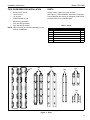
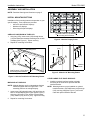
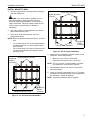
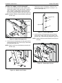
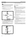
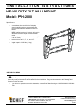
INSTALLATION INSTRUCTIONS
HEAVY DUTY TILT WALL MOUNT
Model: PPH-2000
Specifications:
•
•
•
•
Accomodates Akira and Orion 84" displays
without interface bracket; accomodates other
large flat panel displays with optional interface
bracket.
NOTE: Interface bracket, if required, will result in
additional installation depth. Contact Chief for
details.
Designed for installation on dual wood studs (16"
or 24" on center).
Positive tilt locks at 0°, 5°, 10°, and 15°.
Weight capacity of 250 lbs (113 kg).
BEFORE YOU BEGIN
CAUTION: To prevent damage to your display and this unit, which could affect or void the factory warranty,
thoroughly study all instructions and illustrations before installation. Pay particular attention to the Warnings and
Cautions in this document.
•
If you have any questions about this installation, contact Chief Manufacturing at 1-800-582-6480 or 952-8946280.
CHIEF MANUFACTURING INC.
1-800-582-6480 952-894-6280 FAX 952-894-6918
8401 EAGLE CREEK PARKWAY, STE 700
SAVAGE, MINNESOTA 55378 USA
8805-000068 Rev F
©2006 Chief Manufacturing
www.chiefmfg.com
01/06
Model: PPH-2000
Installation Instructions
IMPORTANT WARNINGS AND CAUTIONS!
WARNING: A WARNING alerts you to the possibility of serious injury or death if you do not follow the instructions.
CAUTION: A CAUTION alerts you to the possibility of damage or destruction of equipment if you do not follow the
corresponding instructions.
WARNING: It is the installer’s responsibility to make sure the structure to which this unit is attached can support five
times the combined weight of all equipment. Reinforce the structure as required before installing the unit. Failure to
provide adequate structural strength for this unit can result in serious personal injury or damage to equipment!
WARNING: It is the installer’s responsibility to make sure all components are properly assembled and installed using
the instructions provided. Failure to follow instructions can result in serious personal injury or damage to equipment!
WARNING: It is the installer’s responsibility to make sure the combined weight of the display, mount, accessories,
and any other attached equipment must not exceed 250 lbs (113 kg), the maximum support weight of this unit.
Exceeding the maximum support weight can result in serious personal injury or damage to equipment!
WARNING: Make sure the latches securing the display are fully closed at all times except when removing or
installing the display. The latches must be fully closed when installing or removing cables from the display.
WARNING: Watch for pinch points. Do not put your fingers between movable parts.
CAUTION: Check the unit for shipping damage before you begin the installation.
DIMENSIONS
2
Installation Instructions
Model: PPH-2000
TOOLS REQUIRED FOR INSTALLATION
•
•
•
•
•
•
•
Drill and 7/32" drill bit
13mm wrench
1/2" wrench
Phillips screwdriver, #2
M5 Hex Key (provided)
3/16" Hex Key (provided)
5/32" Hex Key (provided)
Unpack carton, inspect and verify contents
(See Figure 1). Read installation instructions completely.
If any listed parts are missing or damaged, contact Chief
Customer Service at 1-800-582-6480.
Table 1: Parts
NOTE: Other tools may be required depending on your
method of installation.
(10)
PARTS
(20)
Item
Description
Qty
10
PLATE, Wall
2
20
BRACKET, Static
2
30
ARM, Tilt (long)
2
40
SUPPORT, Side
2
50
LATCH
2
60
ARM, Tilt (short)
2
(30)
(40)
(50)
(60)
Figure 1: Parts
3
Model: PPH-2000
Installation Instructions
(70)
Table 2: Parts (Hardware)
Item
Description
Qty
70
SPACER, 0.194" ID x 0.375" OD x 0.032" long
8
80
SCREW, Button Head Cap, 10-24 x 1/2"
8
90
SCREW, Phillips Pan Machine, 10-24 x 1-1/2"
2
(80)
(90)
100
SCREW, Button Head Cap, M8-1.25 x 25mm
6
110
BUTTON, Mounting
6
120
WASHER, Flat, Machine, M8
6
130
WASHER, Lock, Split, M8
6
140
NUT, Hex, Finished Standard, M8
6
150
SCREW, Button Head Cap, 5/16"-18 x 1/2"
24
(130)
160
PIN, Clevis, 1/2" x 3-1/2"
2
(140)
170
PIN, Clevis, 3/8" x 3-1/2"
2
180
SCREW, Button Head Cap, 3/8"-16 x 3"
2
190
WASHER, Shoulder, 3/8" ID x 3/16" long
8
200
NUT, Lock, Nylok Short, 3/8"-16
2
210
SPACER, 0.5" ID x 0.775" OD x 0.25" long
4
220
PIN, Cotter, 1-5/8" long
230
PIN, Cotter, 2-9/16" long
240
KEY, Hex, 7/32" (very slightly larger than 250)
1
250
KEY, Hex, M5 (very slightly larger than 260)
1
260
KEY, Hex, 3/16"
1
270
KEY, Hex, 1/8"
1
BOLTS, Hex Head Lag, 5/16" x 2-1/2"
(Required, not supplied)
8
WASHER, Flat, Machine, 5/16" (Required, not
supplied)
8
(100)
(110)
(120)
(150)
(160)
(170)
(180)
(190)
(200)
(210)
(220)
(230)
(240)
(250)
(260)
(270)
Figure 2: Parts (Hardware)
4
Installation Instructions
Model: PPH-2000
ASSEMBLY AND INSTALLATION
NOTE: Read the Warnings and Cautions on page 2.
INSTALL MOUNTING BUTTONS
Installation of the mounting buttons is dependent on your
specific display. Three options are provided:
•
•
•
Akira 84" and Orion 84" displays
Modular 84" displays
Other large flat panel displays
Install buttons (110) at these
6 mounting hole locations.
AKIRA 84" AND ORION 84" DISPLAYS
1. Using key (250), insert screw (100) through button
(110) and install into threaded mounting hole on back
of display (See Figure 3). Tighten securely.
Figure 4: Modular Display Frame
2. Repeat for remaining five buttons.
(110)
(110)
Mounting Hole
(100)
(140)
(130)
(120)
Modular
Frame
(100)
Install buttons (110) at these
6 mounting hole locations.
Figure 5: Modular 84" Mounting Button
Figure 3: Akira 84" and Orion 84" Mounting Button
OTHER LARGE FLAT PANEL DISPLAYS
MODULAR 84" DISPLAYS
NOTE: Modular displays are four independent displays
attached together within a single frame. The
assembly performs as a single display.
1. Insert screw (100) through button (110) and frame on
back of modular display (See Figure 4)(See Figure 5).
Using key (250) and 13 mm wrench, install washer
(120), washer (130), and nut (140). Tighten securely.
1. Install the optional interface bracket to display
according to the instructions provided with the
interface bracket.
NOTE: Mounting buttons are pre-installed on optional
interface bracket. PSH-2000 items (100) through
(140), and key (250)(See Figure 1), will not be
used with optional interface bracket.
2. Repeat for remaining five buttons.
5
Model: PPH-2000
Installation Instructions
ASSEMBLE TILT ARM
ASSEMBLE SIDE SUPPORTS
1. Using key (270), loosely install screws (80) through
latch (50) and spacers (70) into threaded holes in arm
(30) (See Figure 6). Ensure latch (50) is installed on
the upper end of arm (30).
1. Using key (260), loosely install support (40) to plate
(10) with screws (150) (See Figure 8). Ensure lip of
support (40) covers edge of plate (10).
2. Repeat for other 3 corners.
3. Once all screws (150) are installed, tighten securely.
(50)
(150)
Threaded
Hole in Arm
(4 Places)
(80)
(4 Places)
(10)
(70)
(4 Places)
(30)
Figure 6: Latch Assembly
(40)
2. Repeat for remaining arm (30).
3. Tighten screws (80) only as required to keep latches
(50) from freely slipping on arm (30). Latches are
designed to slide; do not overtighten screws (80).
4. Slide latch (50) to fully open (raised) position.
5. Using Phillips screwdriver, install screw (90) through
slotted hole in latch (50) into threaded hole in arm (30)
(See Figure 7). Tighten only as required to take up
slack; overtightening will close latch preventing
mounting button installation.
•
If latch begins to close, loosen screw (90) and pull
latch (50) to open position.
(90)
Slotted Hole
in Latch (50)
Threaded Hole
in Latch (50)
Threaded Hole
in Arm (30)
Figure 7: Open Latch
6
Figure 8: Side Support Assembly
Installation Instructions
Model: PPH-2000
INSTALL MOUNT TO WALL
1. Determine approximate mounting location, keeping in
mind the display size.
Left of center installation
Lag Bolt & Washer
(8 Places)
WARNING: The mount must be installed on two or
three wood studs (or other equivalent vertical or
horizontal supporting framework). Do not mount to
single wood studs. Failure to properly install unit can
result in serious personal injury or damage to
equipment!
2. Use a stud sensor to locate applicable wood studs.
Mark locations with a pencil.
3. Level mount at desired height per one of the
configurations below:
NOTE: Either configuration below provides ± 2" of lateral
shift.
•
•
16" on center studs: The mount is approximately
centered between two or three studs as shown
(See Figure 9).
24" on center studs: The mount is offset to the left
or right of center between two studs as shown
(See Figure 10).
Right of center installation
Lag Bolt &
Washer
(8 Places)
Figure 10: 24" On Center Installation
4. Using mount as a template, mark the location of the
pilot holes. Ensure the following:
Lag Bolt &
Washer
(8 Places)
Centered between 2 studs
•
•
Marks are in the center of wood studs.
8 pilot holes are marked (one in each slot).
NOTE: For 16" on center, 3 stud installation: Lag bolts
and washers on center stud are optional.
5. Drill pilot holes using a 7/32" drill bit. Ensure pilot
holes are straight.
6. Using 1/2" wrench, install eight 5/16" x 2 ½" lag bolts
and eight 5/16" washers through mounting holes and
into pilot holes. Tighten all lag bolts.
NOTE: Lag bolts and washers are not supplied.
Centered between 3 studs
Lag Bolt &
Washer
(8 Places)
Figure 9: 16" On Center Stud Installation
7
Model: PPH-2000
Installation Instructions
INSTALL STATIC BRACKETS
AKIRA 84", ORION 84", AND MODULAR 84"
DISPLAYS
1. Using key (260), loosely install brackets (20) to plates
(10) with screws (150) (See Figure 11). Ensure the
following:
• Brackets (20) are installed to outside set of
mounting holes, closest to supports (40).
• Brackets (20) are installed so that square cut outs
are towards top of mount.
2. Tighten all 16 screws (150) securely.
2. Using key (260), loosely install brackets (20) to plates
(10) with screws (150) according to dimension noted
in previous step. Ensure that brackets (20) are
installed so that square cut outs are towards top of
mount.
•
•
•
14" horizontal dimension: Install brackets (20) to
inside set of mounting holes, closest to center of
mount (See Figure 13).
24" horizontal dimension: Install brackets (20) to
middle set of mounting holes (See Figure 14).
33" horizontal dimension: Install brackets (20) to
outside set of mounting holes, closest to supports
(40) (See Figure 11).
3. Tighten all 16 screws (150) securely.
(150)
(16 Places)
(150)
(16 Places)
Square
Cut Out
Square
Cut Out
Figure 11: Installation on Outside Mounting Holes
Figure 13: Installation on Inside Mounting Holes
OTHER LARGE FLAT PANEL DISPLAYS
1. Determine horizontal dimension between mounting
buttons on back of display (or interface bracket, if
required) (See Figure 12).
(150)
(16 Places)
Mounting Buttons
(6 buttons shown;
4 buttons similar)
Square
Cut Out
Back of Display
Figure 12: Horizontal Dimension
8
Figure 14: Installation on Middle Mounting Holes
Installation Instructions
Model: PPH-2000
ATTACH TILT ARMS TO STATIC BRACKET
1. Insert screw (180) through arm (60), washer (190),
bracket (20), washer (190), and arm (60). Install nut
(200). Using key (240), tighten only as required to
take up slack; overtightening will prevent arm (60)
from freely swinging on bracket (20) (See Figure 15).
3. Determine amount of tilt desired. Positive tilt arm
locking holes exist in arm (30) at 0° (no tilt), 5°, 10°,
and 15° (See Figure 17).
NOTE: Washers (190) are nested between bracket (20)
and arm (60).
0° (No Tilt)
5°
10°
(20)
(30)
(190)
(200)
15°
(180)
Figure 17: Tilt Arm Adjustment
4. Insert clevis pin (170) through arm (30) at desired
locking hole, washer (190), arm (60), washer (190),
and arm (30). Install cotter pin (220)(See Figure 18).
(60)
Figure 15: Attach Tilt Support Arm
NOTE: Washers (190) are nested between arm (30) and
arm (60).
2. Insert clevis pin (160) through arm (30), spacer (210),
bracket (20), spacer (210), and arm (30). Install cotter
pin (230) (See Figure 16).
(60)
NOTE: Spacers (210) are nested between bracket (20)
and arm (30).
(30)
(190)
(220)
(20)
(170)
(160)
(210)
(30)
Figure 18: Attach Upper Tilt Arm
(160)
Figure 16: Attach Lower Tilt Arm
9
Model: PPH-2000
Installation Instructions
INSTALL DISPLAY
5. Repeat for second latch (50).
6. Connect cables to display as required.
WARNING: Display is very heavy! Ensure display can
be safely lifted and maneuvered as required to install
on mount. Failure to take adequate precautions can
result in serious personal injury or damage to
equipment!
1. Ensure latches (50) are in fully open (raised) positions
(See Figure 7).
2. Note button openings to be used on each arm (30)
when installing display (See Figure 19).
REMOVE DISPLAY
WARNING: Display is very heavy! Ensure display can
be safely lifted and maneuvered as required to remove
from mount. Failure to take adequate precautions can
result in serious personal injury or damage to
equipment!
1. Disconnect all cables from display.
2. Using Phillips screwdriver, fully remove screw (90)
from threaded hole in bracket (30) (See Figure 7).
3. Re-install screw (90) into threaded hole in latch (50).
Turn screw (90) until latch (50) slides into fully open
position.
4. Repeat for second latch (50).
Six
Button
Installation
Four
Button
Installation
5. Lift and maneuver display mounting buttons (110) out
of button openings.
ADJUST DISPLAY TILT
(20)
Figure 19: Mounting Holes
3. Lift and maneuver display such that all buttons (110)
fit into button openings on arms (30). Lower display
firmly into place. Ensure each button (110) has fully
seated in its button opening.
4. Using Phillips screwdriver, tighten screw (90) until
latch (50) slides into closed position (See Figure 20).
(90)
(50)
Figure 20: Closed Latch
10
NOTE: Depending on the degree of tilt desired, it may be
necessary to remove the display from the mount
prior to making tilt adjustments. See "Remove
Display" above.
1. While supporting display, remove cotter pin (220) and
clevis pin (170) (See Figure 18).
2. Move arm (60) to desired locking hole in arm (30)
(See Figure 17).
3. Re-insert clevis pin (170) through arm (30), washer
(190), arm (60) at desired locking hole, washer (190),
and arm (30). Install cotter pin (220)(See Figure 18).