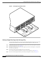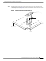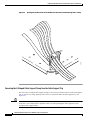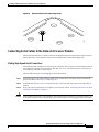
1
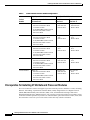
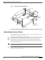
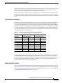
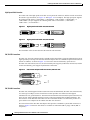
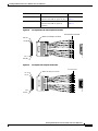
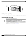
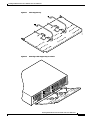
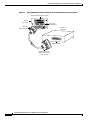
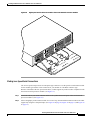
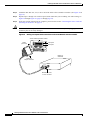
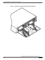
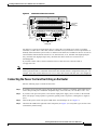
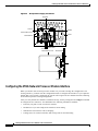
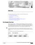
Installing 2T16S Network Processor Modules in
the Cisco 4000 Series
Cisco Product Number: NP-2T16S=
This document contains instructions for installing and configuring 2T16S network processor modules in
Cisco 4000 series routers.
If you have a Cisco 4500-M or Cisco 4700-M router, use this document with the Cisco 4000 Series
Installation Guide and the Regulatory Compliance and Safety Information (previously known as the
Cisco 4000 Series Public Network Certification) document that shipped with your router. If you have a
Cisco 4500 or Cisco 4700 router, refer to the Cisco 4000 Series Hardware Installation and Maintenance
publication.
Note
All documentation is available on a Documentation CD that ships with your router and also on the World
Wide Web (http://www.cisco.com). To order an additional printed manual or the Documentation CD,
contact Customer Service at 800 553-6387, 408 526-7208, or [email protected].
This document contains the following sections, which include step-by-step procedures for installing or
replacing and configuring your new network processor modules:
•
Safety Recommendations, page 2
•
FCC Compliance, page 5
•
Overview of the 2T16S Network Processor Module, page 5
•
Prerequisites for Installing 2T16S Network Processor Modules, page 6
•
Tools and Equipment Required, page 9
•
Preparing to Make Connections, page 9
•
Accessing the Network Processor Modules, page 11
•
Removing Network Processor Modules, page 13
•
Installing Network Processor Modules, page 15
•
Replacing the Component Tray, page 17
•
Reading Chassis Front Panel LEDs, page 17
•
Reading 2T16S Network Processor Module LEDs, page 18
•
2T16S Network Processor Module Port Information, page 18
•
Installing the Cable Support Tray, page 26
Installing 2T16S Network Processor Modules in the Cisco 4000 Series
78-3277-03
1
Installing 2T16S Network Processor Modules in the Cisco 4000 Series
•
Connecting Serial Cables to the Network Processor Module, page 31
•
Connecting the Power Cord and Switching on the Router, page 39
•
Configuring the 2T16S Network Processor Module Interface, page 40
•
Checking the Router Configuration, page 44
•
Problem Solving, page 44
•
Cisco Connection Online, page 46
Safety Recommendations
Follow these guidelines to ensure general safety:
•
Keep the chassis area clear and dust-free during and after installation.
•
Put the removed chassis cover in a safe place.
•
Keep tools away from walk areas where you or others could fall over them.
•
Do not wear loose clothing that could get caught in the chassis. Fasten your tie or scarf and roll up
your sleeves.
•
Wear safety glasses when working under any conditions that might be hazardous to your eyes.
•
Do not perform any action that creates a potential hazard to people or makes the equipment unsafe.
Safety Warnings
Safety warnings appear throughout this publication in procedures that, if performed incorrectly, may
harm you. A warning symbol precedes each warning statement.
Warning
Warning Means danger. You are in a situation that could cause bodily injury. Before you work on any
equipment, be aware of the hazards involved with electrical circuitry and be familiar with standard
practices for preventing accidents. To see translations of the warnings that appear in this publication,
refer to the Regulatory Compliance and Safety Information document that accompanied this device.
Warning
Waarschuwing Dit waarschuwingssymbool betekent gevaar. U verkeert in een situatie die
lichamelijk letsel kan veroorzaken. Voordat u aan enige apparatuur gaat werken, dient u zich bewust
te zijn van de bij elektrische schakelingen betrokken risico's en dient u op de hoogte te zijn van
standaard maatregelen om ongelukken te voorkomen. Voor vertalingen van de waarschuwingen die
in deze publicatie verschijnen, kunt u het document Regulatory Compliance and Safety Information
(Informatie over naleving van veiligheids- en andere voorschriften) raadplegen dat bij dit toestel is
ingesloten.
Warning
Varoitus Tämä varoitusmerkki merkitsee vaaraa. Olet tilanteessa, joka voi johtaa ruumiinvammaan.
Ennen kuin työskentelet minkään laitteiston parissa, ota selvää sähkökytkentöihin liittyvistä
vaaroista ja tavanomaisista onnettomuuksien ehkäisykeinoista. Tässä julkaisussa esiintyvien
varoitusten käännökset löydät laitteen mukana olevasta Regulatory Compliance and Safety
Information -kirjasesta (määräysten noudattaminen ja tietoa turvallisuudesta).
Installing 2T16S Network Processor Modules in the Cisco 4000 Series
2
78-3277-03
Installing 2T16S Network Processor Modules in the Cisco 4000 Series
Warning
Attention Ce symbole d'avertissement indique un danger. Vous vous trouvez dans une situation
pouvant causer des blessures ou des dommages corporels. Avant de travailler sur un équipement,
soyez conscient des dangers posés par les circuits électriques et familiarisez-vous avec les
procédures couramment utilisées pour éviter les accidents. Pour prendre connaissance des
traductions d’avertissements figurant dans cette publication, consultez le document Regulatory
Compliance and Safety Information (Conformité aux règlements et consignes de sécurité) qui
accompagne cet appareil.
Warning
Warnung Dieses Warnsymbol bedeutet Gefahr. Sie befinden sich in einer Situation, die zu einer
Körperverletzung führen könnte. Bevor Sie mit der Arbeit an irgendeinem Gerät beginnen, seien Sie
sich der mit elektrischen Stromkreisen verbundenen Gefahren und der Standardpraktiken zur
Vermeidung von Unfällen bewußt. Übersetzungen der in dieser Veröffentlichung enthaltenen
Warnhinweise finden Sie im Dokument Regulatory Compliance and Safety Information (Informationen
zu behördlichen Vorschriften und Sicherheit), das zusammen mit diesem Gerät geliefert wurde.
Warning
Avvertenza Questo simbolo di avvertenza indica un pericolo. La situazione potrebbe causare
infortuni alle persone. Prima di lavorare su qualsiasi apparecchiatura, occorre conoscere i pericoli
relativi ai circuiti elettrici ed essere al corrente delle pratiche standard per la prevenzione di
incidenti. La traduzione delle avvertenze riportate in questa pubblicazione si trova nel documento
Regulatory Compliance and Safety Information (Conformità alle norme e informazioni sulla sicurezza)
che accompagna questo dispositivo.
Warning
Advarsel Dette varselsymbolet betyr fare. Du befinner deg i en situasjon som kan føre til
personskade. Før du utfører arbeid på utstyr, må du vare oppmerksom på de faremomentene som
elektriske kretser innebærer, samt gjøre deg kjent med vanlig praksis når det gjelder å unngå ulykker.
Hvis du vil se oversettelser av de advarslene som finnes i denne publikasjonen, kan du se i
dokumentet Regulatory Compliance and Safety Information (Overholdelse av forskrifter og
sikkerhetsinformasjon) som ble levert med denne enheten.
Warning
Aviso Este símbolo de aviso indica perigo. Encontra-se numa situação que lhe poderá causar danos
físicos. Antes de começar a trabalhar com qualquer equipamento, familiarize-se com os perigos
relacionados com circuitos eléctricos, e com quaisquer práticas comuns que possam prevenir
possíveis acidentes. Para ver as traduções dos avisos que constam desta publicação, consulte o
documento Regulatory Compliance and Safety Information (Informação de Segurança e Disposições
Reguladoras) que acompanha este dispositivo.
Warning
¡Advertencia! Este símbolo de aviso significa peligro. Existe riesgo para su integridad física. Antes
de manipular cualquier equipo, considerar los riesgos que entraña la corriente eléctrica y
familiarizarse con los procedimientos estándar de prevención de accidentes. Para ver una traducción
de las advertencias que aparecen en esta publicación, consultar el documento titulado Regulatory
Compliance and Safety Information (Información sobre seguridad y conformidad con las
disposiciones reglamentarias) que se acompaña con este dispositivo.
Installing 2T16S Network Processor Modules in the Cisco 4000 Series
78-3277-03
3
Installing 2T16S Network Processor Modules in the Cisco 4000 Series
Warning
Varning! Denna varningssymbol signalerar fara. Du befinner dig i en situation som kan leda till
personskada. Innan du utför arbete på någon utrustning måste du vara medveten om farorna med
elkretsar och känna till vanligt förfarande för att förebygga skador. Se förklaringar av de varningar
som förkommer i denna publikation i dokumentet Regulatory Compliance and Safety Information
(Efterrättelse av föreskrifter och säkerhetsinformation), vilket medföljer denna anordning.
Warning
Read the installation instructions before you connect the system to its power source.
Warning
Only trained and qualified personnel should be allowed to install or replace this equipment.
Warning
Before working on a chassis or working near power supplies, unplug the power cord on AC units;
disconnect the power at the circuit breaker on DC units.
Warning
Ultimate disposal of this product should be handled according to all national laws and regulations.
Caution
To avoid damaging ESD-sensitive components, discharge all static electricity from your body before
opening the chassis. Before performing procedures described in this document, review the sections
“Safety with Electricity,” “Safety with Electricity,” and “Tools and Equipment Required.”
Note
The following warnings are only applicable if a single-mode Fiber Distributed Data Interface (FDDI or
Basic Rate Interface (BRI) network processor module are installed in the router together with 2T16S
network processor modules. If you do not have these modules installed in your router, proceed with the
section “Overview of the 2T16S Network Processor Module on page 5.
Warning
The ports labeled “Ethernet,” “10BaseT,” “Token Ring,” “Console,” and “AUX” are safety extra-low
voltage (SELV) circuits. SELV circuits should only be connected to other SELV circuits. Because the
BRI circuits are treated like telephone-network voltage, avoid connecting the SELV circuit to the
telephone network voltage (TNV) circuits.
Warning
The ISDN connection is a source of voltage that should be inaccessible to user contact. Do not attempt
to tamper with or open any public telephone operator (PTO)-provided equipment or connection
hardware. Any hardwired connection (other than by nonremovable, connect-one-time-only lug) must
be made only by PTO staff or suitably trained engineers.
Warning
Network hazardous voltages are present in the BRI cable. If you detach the BRI cable, detach the end
away from the router first to avoid possible electric shock. Network hazardous voltages also are
present on the system card in the area of the BRI port (RJ-45 connector), regardless of when power is
turned off.
Installing 2T16S Network Processor Modules in the Cisco 4000 Series
4
78-3277-03
Installing 2T16S Network Processor Modules in the Cisco 4000 Series
Warning
Warning Invisible laser radiation may be emitted from the aperture ports of the single-mode FDDI
card and single-mode ATM cards when no cable is connected. Avoid exposure and do not stare into
open apertures. The following is an example of the warning label that appears on the product:
WARNING
1300NM
CLASS 1 LASER PRODUCT
H3159
AVOID EXPOSURE–Invisible Laser radiation is emitted from transmit ports.
FCC Compliance
The 2T16S network processor module is verified to FCC Class B.
Overview of the 2T16S Network Processor Module
The 2T16S network processor module provides 2 high-speed synchronous serial ports and 16 low-speed
synchronous ports. Figure 1 shows a generic 2T16S network processor module panel, and Table 1
describes all available 2T16S modules and port configurations.
Figure 1
2T16S Network Processor Module
0-7
17 16
1514
1312
1110
Low-speed
200-pin
serial ports
LEDs
9
7
5
3
8
6
4
2
P1
SERIAL
P0
H6412
0-7
High-speed 60-pin
serial ports
Installing 2T16S Network Processor Modules in the Cisco 4000 Series
78-3277-03
5
Installing 2T16S Network Processor Modules in the Cisco 4000 Series
Table 1
2T16S Network Processor Module Configurations
2 High-Speed Serial Connectors
2 Low-Speed Serial Connectors
Product
Number
Right Connector and Left Connector
Port 0 and Port 1
Middle Connector
Ports 2 to 9
Top Connector
Ports 10 to 17
2T16S-RS232
Choice of
EIA/TIA-232 DTE or DCE
V.35 DTE or DCE
X.21(NRZ/NRZ1) DTE or DCE
EIA/TIA-449, DTE or DCE
EIA-530A DTE
All 8 ports are
EIA/TIA-232
DTE or DCE
All 8 ports are
EIA/TIA-232
DTE or DCE
2T16S-V.35
Choice of
EIA/TIA-232 DTE or DCE
V.35 DTE or DCE
X.21(NRZ/NRZ1) DTE or DCE
EIA/TIA-449, DTE or DCE
EIA-530A DTE
All 8 ports are
V35
DTE or DCE
All 8 ports are
V.35
DTE or DCE
2T16S-X.21
Choice of
EIA/TIA-232 DTE or DCE
V.35 DTE or DCE
X.21(NRZ/NRZ1) DTE or DCE
EIA/TIA-449, DTE or DCE
EIA-530A DTE
All 8 ports are
X.21
DTE or DCE
All 8 ports are
X.21
DTE or DCE
2T16S-232V35
Choice of
EIA/TIA-232 DTE or DCE
V.35 DTE or DCE
X.21(NRZ/NRZ1) DTE or DCE
EIA/TIA-449, DTE or DCE
EIA-530A DTE
All 8 ports are
EIA/TIA-232
DTE or DCE
All 8 ports are
V.35
DTE or DCE
2T16S-232X21
Choice of
EIA/TIA-232 DTE or DCE
V.35 DTE or DCE
X.21(NRZ/NRZ1) DTE or DCE
EIA/TIA-449, DTE or DCE
EIA-530A DTE
All 8 ports are
EIA/TIA-232
DTE or DCE
All 8 ports are
X.21
DTE or DCE
Prerequisites for Installing 2T16S Network Processor Modules
The Cisco 4000 series routers can support up to three network processor modules at a time, including
Ethernet, Token Ring, Asynchronous Transfer Mode (ATM), Integrated Services Digital Network
(ISDN) BRI, ISDN Primary Rate Interface (PRI), serial, and multimode and single-mode Fiber
Distributed Data Interface (FDDI) interfaces. You can place 2T16S network processor modules in any
of the three available positions. If you have two 2T16S modules, place them in slots 0 and 2 (outer) slots.
This will make it easier for you to route cables on the cable tray (which is included).
Installing 2T16S Network Processor Modules in the Cisco 4000 Series
6
78-3277-03
Installing 2T16S Network Processor Modules in the Cisco 4000 Series
Software Compatibility
Network processor modules must be supported by the appropriate level of system software. The
minimum system software version for the 2T16S network processor module is as follows:
•
2T16S-RS232 and 2T16S-V.35—Cisco IOS Release 11.2(3)P for synchronous and Cisco IOS
Release 11.2(4)P for asynchronous operation
•
2T16S-X.21—Cisco IOS Release 11.2(5)P
•
2T16S-232V35 and 2T16S-232X21—Cisco IOS Release 11.2(5)P
If you have an earlier version of Cisco IOS software, contact Cisco Customer Service (see the section at
the end of this document, “Cisco Connection Online”) or your local sales representative to order the
appropriate version.
Memory Requirements
To successfully operate a system with 6 or more ports, the system must contain at least 4 MB of shared
memory. To successfully operate a system with 24 or more ports, the system must contain at least 8 MB
of main memory DRAM.
Memory requirements for each 2T16S network processor module follow:
•
275 KB (0.275 MB) main memory
•
0.63 MB shared memory
Safety with Electricity
Warning
Before working on equipment that is connected to power lines, remove jewelry (including rings,
necklaces, and watches). Metal objects will heat up when connected to power and ground and can
cause serious burns or weld the metal object to the terminals.
Warning
To avoid electric shock, do not connect safety extra-low voltage (SELV) circuits to
telephone-network voltage (TNV) circuits. LAN ports contain SELV circuits, and WAN ports contain
TNV circuits. Both LAN and WAN ports may use RJ-45 connectors. Use caution when connecting
cables.
Warning
Hazardous network voltages are present in WAN ports regardless of whether power to the router is
OFF or ON. To avoid electric shock, use caution when working near WAN ports. When detaching
cables, detach the end away from the router first.
Warning
The ISDN connection is regarded as a source of voltage that should be inaccessible to user contact.
Do not attempt to tamper with or open any public telephone operator (PTO)-provided equipment or
connection hardware. Any hardwired connection (other than by a nonremovable,
connect-one-time-only plug) must be made only by PTO staff or suitably trained engineers.
Follow these guidelines when working on equipment powered by electricity:
Installing 2T16S Network Processor Modules in the Cisco 4000 Series
78-3277-03
7
Installing 2T16S Network Processor Modules in the Cisco 4000 Series
•
Locate the room’s emergency power-off switch. Then, if an electrical accident occurs, you can
quickly turn OFF the power.
•
Before working on the system, turn OFF the power and unplug the power cord.
•
Disconnect all power before doing the following:
– Installing or removing a router chassis or network processor module
– Working near power supplies
– Performing a hardware upgrade
•
Do not work alone if potentially hazardous conditions exist.
Warning
Before opening the chassis, disconnect the telephone-network cables to avoid contact with
telephone-network voltages.
Warning
Do not work on the system or connect or disconnect cables during periods of lightning activity.
•
Warning
Never assume that power is disconnected from a circuit. Always check.
Do not touch the power supply when the power cord is connected. For systems with a power switch,
line voltages are present within the power supply even when the power switch is OFF and the power
cord is connected. For systems without a power switch, line voltages are present within the power
supply when the power cord is connected.
•
Look carefully for possible hazards in your work area, such as moist floors, ungrounded power
extension cables, and missing safety grounds.
•
Never assume that power is disconnected from a circuit. Always check.
•
If an electrical accident occurs, proceed as follows:
– Use caution, and do not become a victim yourself.
– Turn OFF power to the system.
– If possible, send another person to get medical aid. Otherwise, determine the condition of the
victim and then call for help.
– Determine if the person needs rescue breathing or external cardiac compressions; then take
appropriate action.
Preventing Electrostatic Discharge Damage
Electrostatic discharge (ESD) can damage equipment and impair electrical circuitry. It occurs when
electronic printed circuit cards are improperly handled and can result in complete or intermittent
failures. Always follow ESD prevention procedures when removing and replacing cards. Ensure that the
router chassis is electrically connected to earth ground. Wear an ESD-preventive wrist strap, ensuring
that it makes good skin contact. Connect the clip to an unpainted surface of the chassis frame to safely
channel unwanted ESD voltages to ground. To properly guard against ESD damage and shocks, the wrist
strap and cord must operate effectively. If no wrist strap is available, ground yourself by touching the
metal part of the chassis.
Installing 2T16S Network Processor Modules in the Cisco 4000 Series
8
78-3277-03
Installing 2T16S Network Processor Modules in the Cisco 4000 Series
Caution
For safety, periodically check the resistance value of the antistatic strap, which should be between 1 and
10 megohm (Mohm).
Tools and Equipment Required
You need the following tools and equipment for removing and installing 2T16S network processor
modules in a Cisco 4000 series router:
•
ESD wrist strap and mat
•
Screwdrivers, Number 1 and Number 2 Phillips
Preparing to Make Connections
The power cable and on/off switch are on the lower right of the rear panel of the router. The system
console port, auxiliary port, and network processor module ports (labeled 2T16S serial module and
Ethernet module in Figure 2) appear to the left of the power cable and switch.
Figure 2
Cisco 4000 Series—Rear View Showing Slot Numbering and Interface Ports
Slot 1
2T16S
serial
module
10BaseT
ports
H8640
Slot 3
2T16S
serial
module
Slot 2
Ethernet
module
P0
L
RIA
SE
P1
On/off
switch
-1
RT
PO
TX
RX
I
AUK
LN L
PO
Power
-0
T
OR
-T P
SE
BA
10
Console port
TX
RX
I
AUK
LN L
PO
P0
L
RIA
SE
Auxiliary port
P1
Installing 2T16S Network Processor Modules in the Cisco 4000 Series
78-3277-03
9
Installing 2T16S Network Processor Modules in the Cisco 4000 Series
Slot Numbering
The chassis contains slots for three network processor modules. These slots correspond to the three slot
numbers printed on the front panel of the chassis. (See Figure 3.) Slot numbers represent the order in
which the system scans the network processor modules. The location of network processor modules is
not slot dependent; you can move any module to any other available slot.
Figure 3
Cisco 4000 Series—Front View
Run LED
Network activity LEDs
1
2
3
DATA
DATA
DATA
OK
OK
OK
OK
POWER
Health LEDs
H2427
SERIES
Power LED
Unit Numbering
Unit numbering allows the system to distinguish between two interfaces of the same type. Looking at
the rear panel of the chassis, the unit numbering of the network processor modules increments from zero,
counting from right to left. The system assigns unit number addresses to these network processor
modules by starting with zero for each module interface type and numbering from right to left and from
bottom to top. The lowest unit number of that interface type is the module closest to the power supply.
(See Figure 2.) For example, the unit number addresses for the modules in Figure 2 are as listed in
Table 2.
Table 2
Unit Number Addresses for Two 2T16S Modules and One Ethernet Module
Slot
Interface Type
Address
1
Low-speed serial port (top)
Low-speed serial port (middle)
High-speed serial port (left)
High-speed serial port (right)
10 to 17
2 to 9
1
0
2
Ethernet port (top)
Ethernet port (bottom)
1
0
3
Low-speed serial port (top)
Low-speed serial port (middle)
High-speed serial port (left)
High-speed serial port (right)
28 to 35
20 to 27
19
18
Installing 2T16S Network Processor Modules in the Cisco 4000 Series
10
78-3277-03
Installing 2T16S Network Processor Modules in the Cisco 4000 Series
If the second 2T16S module in Figure 2 was replaced by an Ethernet module, the unit addresses would
be as listed in Table 3.
Table 3
Unit Number Addresses for Serial and Two Ethernet Modules
Slot
Interface Type
Address
1
Low-speed serial port (top)
Low-speed serial port (middle)
High-speed serial port (left)
High-speed serial port (right)
10 to 17
2 to 9
1
0
2
Ethernet port (top)
Ethernet port (bottom)
1
0
3
Ethernet port (top)
Ethernet port (bottom)
3
2
Accessing the Network Processor Modules
To access the network processor modules, you must remove the component tray.
Removing the Component Tray Procedure
Some Cisco 4000 series routers have a safety latch tab on the chassis that affects removing the
component tray. (See Figure 4 and Figure 5.)
If you have a chassis with a safety latch tab, follow the procedure in the next section “Removing the
Component Tray from a Chassis with a Safety Latch.”
If you have a chassis without a safety latch tab, follow the procedure in the section “Removing the
Component Tray from a Chassis without a Safety Latch.”
Removing the Component Tray from a Chassis with a Safety Latch
Warning
Hazardous voltages may exist in or near the power supply, so use extreme caution when working near
the power supply. Before starting any of these procedures, turn OFF power to the system, unplug the
power cord, disconnect any cables at the ports, and attach your ESD-preventive wrist strap.
Take the following steps to remove the component tray from a chassis with a safety latch:
Step 1
Turn OFF the system power.
Step 2
Attach your ESD-preventive wrist strap to your wrist and the other end to a grounded surface.
Step 3
Remove all network and power cables.
Step 4
Loosen the nonremovable chassis release screw on the rear panel of the chassis. (See Figure 4.)
Step 5
Pull on the handle located on the upper right corner of the chassis to slide the component tray out of the
chassis shell until the safety latch catches. (See Figure 4.)
Installing 2T16S Network Processor Modules in the Cisco 4000 Series
78-3277-03
11
Installing 2T16S Network Processor Modules in the Cisco 4000 Series
Warning
Before releasing the safety latch, support the component tray from underneath, either on your work
surface or with your hands, to prevent personal injury. (See Figure 4.)
Figure 4
Component Tray Removal for Chassis with a Safety Latch
Chassis shell
Safety latch tab
Chassis release
screw
TX
RX
AUI
LNK
POL
PORT-1
10BASE-T PORT-0
TX
RX
AUI
LNK
POL
P1
P0
SERIAL
P0
SERIAL
INPUT 100-240VAC
Rear of chassis
Hand supporting
component tray
50/60HZ 3.0-1.5 AMPS
H8641
P1
Handle
Step 6
Support the component tray with one hand, push down on the safety latch tab, and pull the component
tray out the rest of the way.
Step 7
Set the component tray on your work surface.
Proceed to the next section “Removing Network Processor Modules.”
Removing the Component Tray from a Chassis without a Safety Latch
Warning
Hazardous voltages may exist in or near the power supply, so use extreme caution when working near
the power supply. Before starting any of these procedures, turn OFF power to the system, unplug the
power cord, disconnect any cables at the ports, and connect your ESD-preventive wrist strap.
Take the following steps to remove the component tray from a chassis without a safety latch:
Step 1
Turn OFF the system power.
Step 2
Attach your ESD-preventive wrist strap.
Step 3
Remove all network and power cables.
Step 4
Loosen the nonremovable chassis release screw on the rear panel of the chassis. (See Figure 5.)
Installing 2T16S Network Processor Modules in the Cisco 4000 Series
12
78-3277-03
Installing 2T16S Network Processor Modules in the Cisco 4000 Series
Warning
Support the component tray from underneath, either on your work surface or with your hands, to
prevent it from falling. (See the hand in Figure 5.)
Figure 5
Component Tray Removal for Chassis without a Safety Latch
Chassis shell
Chassis release
screw
TX
RX
AUI
LNK
POL
PORT-1
10BASE-T PORT-0
TX
RX
AUI
LNK
POL
P0
P1
SERIAL
P0
SERIAL
INPUT 100-240VAC
Rear of chassis
Hand supporting
component tray
50/60HZ 3.0-1.5 AMPS
H8642
P1
Handle
Step 5
Pull on the handle located on the upper right corner of the chassis to slide the component tray out of the
chassis shell while you support the component tray with one hand.
Step 6
Set the component tray on your work surface.
Proceed to the later section “Removing Network Processor Modules.”
Removing Network Processor Modules
After you have removed the component tray from the chassis, you can remove the network processor
modules from the chassis.
Caution
Some network processor modules are secured to the rear of the chassis with two external screws. On
modules with external rear mounting screws, including multimode FDDI modules, you must remove
these screws before the module can be safely lifted out of the chassis.
Take the following steps to remove a network processor module:
Step 1
Orient the component tray as shown in Figure 6, then remove the module mounting screw from the top
of the network processor module. Remove the two external rear mounting screws if the module has them.
Set all screws aside.
Installing 2T16S Network Processor Modules in the Cisco 4000 Series
78-3277-03
13
Installing 2T16S Network Processor Modules in the Cisco 4000 Series
Step 2
Grasp the network processor module handle and pull it straight up to lift the module out of its connector.
(See Figure 6.)
Step 3
Place the removed module on an ESD mat.
Caution
Do not wiggle the handle of the network processor module, and do not exert any side-to-side pressure
because the handle might work loose and damage the network processor module.
Figure 6
Cisco 4000 Series Component Tray—Cisco 4000-M Shown
Module
mounting
screws
Module handle
LED
J1
Front
of the
chassis
Module handle
LEDs
FW1
FW2
128-pin connector
Caution
H8643
Module handle
Boot ROMs
If any of the network processor modules have daughter cards projecting at right angles to the module
(see Figure 10), do not bend the module during installation. Bending the module might cause the
daughter cards to become disconnected. If this happens, carefully reseat the daughter card connectors by
handling the card by its edges without touching any of the components on the card.
Installing 2T16S Network Processor Modules in the Cisco 4000 Series
14
78-3277-03
Installing 2T16S Network Processor Modules in the Cisco 4000 Series
Figure 7
Network Processor Module Components
Module handles
Male module
connector
(cutaway view)
Female module
connector on the
motherboard
Safety latch
H1048a
Chassis
wall
Module mounting
screw
Installing Network Processor Modules
You can install up to three 2T16S network processor modules per chassis. Take the following steps to
replace or add a 2T16S network processor module:
Step 1
Hold the module over the empty slot, just above the chassis.
Step 2
Align it with the grooves in the chassis and the 128-pin female connector on the motherboard.
Step 3
Holding the module at an angle with its faceplate lower than the other end, slip the upper 200-pin
connector through the opening in the back panel of the chassis. Make sure the flange of the module
extends over the top of the chassis.
Note
Step 4
Unlike other network processor modules that can be lowered straight into the chassis, the 2T16S module
must be tipped as described in Step 4.
Rotate the module, moving it downward and forward until the module connector is aligned with the
motherboard connector as shown in Figure 8.
Installing 2T16S Network Processor Modules in the Cisco 4000 Series
78-3277-03
15
Installing 2T16S Network Processor Modules in the Cisco 4000 Series
Aligning the 2T16S Network Processor Module with the Chassis
H8761
Figure 8
Step 5
Make sure that the male connector on the network processor module is lined up side-to-side with the
female connector on the motherboard, and then gently press point A shown in Figure 9.
Figure 9
Pressing the 2T16S Network Processor Module into Place
B
H8762
A
Step 6
Gently press point B as shown in Figure 9, inserting the male connector into the female connector on the
motherboard. With a small amount of force the connector snaps together.
Make sure that the connector on the network processor module is firmly seated on the female connector
on the motherboard. (See Figure 10.)
Installing 2T16S Network Processor Modules in the Cisco 4000 Series
16
78-3277-03
Installing 2T16S Network Processor Modules in the Cisco 4000 Series
Figure 10
Correct Installation of the Network Processor Module
Incorrect installation showing
connectors not firmly seated.
H8760
Correct installation showing
connectors firmly seated.
Step 7
Replace the module mounting screw in its place on the end of the network processor module. (See
Figure 6.)
Step 8
Replace external rear mounting screws, if used, to attach the module to the rear of the chassis.
Caution
Do not overtorque the screws because they might damage the network processor module or the
underlying motherboard. The maximum screw torque is 7-inch-lb.
Replacing the Component Tray
Take the following steps to replace the component tray in the chassis shell:
Step 1
Reinsert the component tray into the shell, pushing on the back of the tray while at the same time
pressing on the chassis release screw (as shown in Figure 4 on page 12 and Figure 5 on page 13) with
the thumb of your right hand.
Step 2
Retighten the chassis release screw.
Reading Chassis Front Panel LEDs
Figure 3 on page 10 shows the Cisco 4000 series chassis front view with network activity, health, run,
and power LEDs.
Installing 2T16S Network Processor Modules in the Cisco 4000 Series
78-3277-03
17
Installing 2T16S Network Processor Modules in the Cisco 4000 Series
When you face the front of the chassis, the three LEDs (labeled OK) on the lower left correspond to the
three network processor modules, if present. (See Figure 2.) When on, these LEDs indicate that the
network processor modules are operational. The upper LEDs (labeled DATA) blink to indicate network
activity on the respective interfaces. If no network processor module is installed in a slot, the LEDs
corresponding to that slot will be off.
The LED labeled POWER goes on to indicate that the system power is on. The LED labeled OK goes on
to indicate that the system’s processor is working.
The network processor module LEDs are visible through the cutouts in the rear of the chassis.
Reading 2T16S Network Processor Module LEDs
The 2T16S network processor module has one green LED per port, each of which indicates Connect
status. All LEDs momentarily light up during reset as a ‘lamp test’ feature. The LEDs indicate the
following signals: DSR, DTR, DCD, RTS, and CTS. The Connect status is the logical operand AND for
all listed modem control signals. In DTE mode, Connect is DSR, DCD, and CTS. In DCE mode, Connect
is DTR and RTS.
2T16S Network Processor Module Port Information
The 2T16S network processor module for Cisco 4000 series routers provide 2 high-speed serial ports
and 16 low-speed serial ports. Each high-speed serial port supports one of nine cable types:
•
EIA/TIA-232, DTE or DCE
•
V.35, DTE or DCE
•
X.21(NRZ/NRZ1), DTE or DCE
•
EIA/TIA-449, DTE or DCE
•
EIA-530A, DTE
The low-speed serial ports support an octal cable. The eight legs of each octopus cable are all DTE or
all DCE. ( Table 1 on page 6 shows port configurations.)
•
2T16S-RS232 low-speed ports require EIA/TIA-232 octal cables
•
2T16S-V.35 low-speed ports require V.35 octal cables
•
2T16S-X.21 low-speed ports require X.21 octal cables
•
2T16S-232V.35 low-speed ports require V.35 octal cables (upper connector) and EIA/TIA-232
(middle connector)
•
2T16S-232X21 low-speed ports require X.21 octal cables (upper connector) and EIA/TIA-232
(middle connector)
For information about cables that connect to the low-speed serial ports, see the sections “Low-Speed
Serial Cables,” page 24 or “High-Speed Serial Cables,” page 21. For pinout descriptions, see the section
“Cabling Specifications” in the Cisco 4000 Series Installation Guide. Although the printed manual ships
with your router, the most current version appears on the on the World Wide Web at
http://www.cisco.com and on the Documentation CD that ships with your router.
Information in this section includes port specifications, throughput, distance limitations, and
connections.
Installing 2T16S Network Processor Modules in the Cisco 4000 Series
18
78-3277-03
Installing 2T16S Network Processor Modules in the Cisco 4000 Series
High-Speed Serial Ports
The two high-speed synchronous serial ports use two 60-pin D-type connectors to attach to the transition
cable. Each port requires a serial adapter cable, which provides the interface between the high-speed
serial port and the standard connectors that are commonly used for each electrical interface type. The
adapter cable determines the electrical interface type and mode (DTE or DCE) of the port to which it is
connected. Because the high-speed serial ports use a special, high-density port connector that requires
special adapter cables for each electrical interface type, we recommend that you obtain serial interface
cables from the factory.
The high-speed serial port specifications are as follows:
•
Supports speeds up to 2.048 Mbps synchronous, full duplex
•
NRZ, NRZI encoding/decoding
•
DCE/DTE mode
•
CRC-CCITT (16-bit) supported, no CRC-32
•
Full/half duplex
•
Supports EIA/TIA-232, V.35, X.21, EIA/TIA-449, and EIA-530A interfaces
•
60-pin Cisco standard connector; configuration determined by transition cable type
For most interface types, the adapter cable for DTE mode uses a plug at the network end, and the cable
for DCE mode uses a receptacle at the network end. The exception is the V.35 adapter cable, which is
available with either a V.35 plug or a receptacle for either mode. The mode, DCE or DTE, is labeled on
the molded plastic connector shell at the ends of all cables except V.35 (which uses the standard
Winchester block-type connector instead of a molded plastic D-shell). Following are the available
interface cable options for the mode and network-end connectors for each cable:
Caution
•
EIA/TIA-232: DTE mode with a DB-25 plug; DCE mode with a DB-25 receptacle
•
V.35: DTE mode or DCE mode with a 34-pin Winchester-type V.35 plug; DTE mode or DCE mode
with a 34-pin Winchester-type V.35 receptacle
•
X.21: DTE mode with a DB-15 plug; DCE mode with a DB-15 receptacle
•
EIA-TIA-449: DTE mode with a 37-pin D-shell plug; DCE mode with a 37-pin D-shell receptacle
•
EIA-530A: DTE mode with a DB-25 plug
For proper router operation, both ends of the EIA/TIA-232 serial DCE cable, and any cable attached to
it, must be connected. If you must detach this cable, detach the router end first. If the end away from the
router is disconnected, the line connection will “flap.” The interrupts generated from such a condition
could cause the router to shut down.
Low-Speed Serial Ports
The 16 low-speed serial ports use two 200-pin D-type connectors to attach to the transition cable. Each
200-pin connector requires a transition cable to break out the 8 low-speed serial ports interfaced by the
connector. Together, each 200-pin connector and the 8 associated low-speed serial port cables are called
an “octopus” cable (see Figure 18 through Figure 20 for illustrations of the cable). Each 200-pin port is
independent of the other 200-pin port.
Installing 2T16S Network Processor Modules in the Cisco 4000 Series
78-3277-03
19
Installing 2T16S Network Processor Modules in the Cisco 4000 Series
The adapter cable also determines the electrical interface type and mode (DCE or DTE) of the port to
which it is connected. Because the low-speed serial ports require special adapter cables, we recommend
that you obtain serial interface cables from Cisco Systems (contact Customer Service at 800 553-6387,
408 526-7208, or [email protected]).
Note
The eight legs of each octopus cable are all DTE or all DCE, and they must all be the same interface type
(EIA/TIA-232, V.35, X.21, mixed EIA/TIA-232 and V.35, or mixed EIA/TIA-232 and X.21) as the
module interface type (NP-2T16S-RS232, NP-2T16S-V.35, or NP-2T16S-X.21, NP-2T16S-232V35, or
respectively NP-2T16S-232X21). You cannot mix DTE/DCE and interface types within a cable; the
low-speed serial ports are not Cisco serial 5-in-1 serial ports.
The low-speed serial port specifications are as follows:
•
Supports synchronous speeds up to 128 Kbps, full duplex
•
Supports asynchronous speeds up to 115.2 Kbps, full duplex
•
NRZ, NRZI encoding/decoding
•
DCE/DTE mode
•
Full/half duplex
•
Supports EIA/TIA-232, V.35, and X.21 interfaces
•
200-pin Cisco standard connector; configuration determined by transition cable type
For most interface types, the adapter cable for DTE mode uses plugs at the network end, and the cable
for DCE mode uses receptacles at the network end. The exception is the V.35 adapter cable, which is
available with either V.35 plugs or receptacles for either mode. The mode, DCE or DTE, is labeled on
the molded plastic connector shell at the ends of all cables except V.35 (which uses the standard
Winchester block-type connector instead of a molded plastic D-shell).
Following are the available interface cable options for the mode and network-end connectors for each
cable:
Caution
•
EIA/TIA-232: DTE mode with DB-25 plugs; DCE mode with DB-25 receptacles
•
V.35: DTE mode or DCE mode with 34-pin Winchester-type V.35 plugs; DTE mode or DCE mode
with 34-pin Winchester-type V.35 receptacles
•
X.21: DTE mode with DB-15 plugs; DCE mode with DB-15 receptacles
For proper router operation, both ends of the EIA/TIA-232 serial DCE cable, and any cables attached to
it, must be connected. If you must detach this cable, detach the router end first. If the end away from the
router is disconnected, the line connection will “flap.” The interrupts generated from such a condition
could cause the router to shut down.
Clocking and Aggregate 2T16S Network Processor Module Throughput
The following configuration requirements must be met for proper operation of the 2T16S module:
•
The maximum aggregate throughput of the module is 11.7 Mbps.
•
No high-speed port can be clocked at a rate higher than 2.048 Mbps synchronous full duplex or
4 Mbps synchronous half duplex.
•
All 16 low-speed serial ports can run simultaneously up to 115.2 Kbps full duplex with no
restrictions.
Installing 2T16S Network Processor Modules in the Cisco 4000 Series
20
78-3277-03
Installing 2T16S Network Processor Modules in the Cisco 4000 Series
The data rate depends on the type of electrical interface used. EIA/TIA-232 only supports speeds up to
64 kbps; X.21, V.35, EIA/TIA-449, or EIA-530A support higher speeds. Note that EIA/TIA-449 or
EIA-530A interfaces are only supported on the high-speed serial ports.
When connecting serial devices, consider the adapter cables as an extension of the router for external
connections. Therefore, use DTE cables to connect the router to remote DCE devices such as modems
or DSUs, and use DCE cables to connect the router to remote DTE devices such as a host, PC, or another
router.
Serial Distance Limitations
Serial signals can travel a limited distance at any given bit rate; generally, the slower the transmission
(baud) rate, the greater the distance. All serial signals are subject to distance limits, beyond which a
signal degrades significantly or is completely lost. Table 3 lists the recommended maximum speeds and
distances for each serial interface type from the IEEE specification; however, you might get good results
at speeds and distances greater than those listed. If you understand the electrical problems that might
arise and can compensate for them, you can get good results with rates and distances greater than those
shown. However, do so at your own risk.
Table 4
IEEE Standard Transmission Speed Versus Distance
Data Rate
EIA/TIA-232 Distances
EIA/TIA-449, EIA-530A,
X.21, and V.35 Distances
Bits per Second
Feet
Meters
Feet
Meters
2400
200
60
4100
1250
4800
100
30
2050
625
9600
50
15
1025
312
19200
25
7.6
513
156
38400
12
3.7
256
78
56000
8.6
2.6
102
31
1544000 (T1)
N/A
N/A
50
15
Balanced drivers allow EIA/TIA-449 signals to travel greater distances than EIA/TIA-232 signals. The
recommended distance limits for EIA/TIA-449 shown in Table 3 are also valid for V.35, X.21, and
EIA-530A. However, you can get good results at distances and rates greater than those shown in Table 3.
Typically, EIA/TIA-449 and EIA/530A support 2-Mbps rates, and V.35 can support 4-Mbps rates
(2-Mbps in the 2T16S network processor module).
High-Speed Serial Cables
This section describes the high-speed cable connectors. For pinout descriptions, see the section “Cabling
Specifications” in the Cisco 4000 Series Installation Guide. Although the printed manual ships with your
router, the most current version appears on the on the World Wide Web at http://www.cisco.com and
on the Documentation CD that ships with your router.
Installing 2T16S Network Processor Modules in the Cisco 4000 Series
78-3277-03
21
Installing 2T16S Network Processor Modules in the Cisco 4000 Series
High-Speed Cable Overview
The router-end of the high-speed serial cable is a 60-pin D-sub connector, and the network end reflects
the interface type and mode (see Figure 11 and Figure 12 for examples). The high-speed port supports
the following DTE cables: CAB-232MT=, CAB-449MT=, CAB-V35MT=, CAB-X21MT=, or
CAB-530MT=; the port supports the following DCE cables: CAB-232FC=, CAB-449FC=,
CAB-V35FC=, or CAB-X21FC=.
High-Speed Serial Cable—EIA/TIA-232 DTE
Figure 12
High-Speed Serial Cable—EIA/TIA-232 DCE
H5669
H5670
Figure 11
This remainder of this section describes the network-end connectors.
EIA/TIA-232 Connections
EIA/TIA-232, the most common interface standard in the United States, supports unbalanced circuits at
signal speeds up to 64 kbps. The network end of the adapter cable is a standard 25-pin D-shell connector
(known as a DB-25, as shown in Figure 13). The router console and auxiliary ports also use
EIA/TIA-232 connections; however, the serial module ports support synchronous connections, and the
console and auxiliary ports support asynchronous connections.
Figure 13
EIA/TIA-232 Adapter Cable Connectors, Network End
DCE
H1343a
DTE
EIA/TIA-449 Connections
EIA/TIA-449, which supports balanced (EIA/TIA-422) and unbalanced (EIA/TIA-423) transmissions,
is a faster (up to 2 Mbps) version of EIA/TIA-232 that provides more functions and supports
transmissions over greater distances. The EIA/TIA-449 standard was intended to replace EIA/TIA-232,
but it was not widely adopted primarily because of the large installed base of DB-25 hardware. The
increased size of the EIA/TIA-449 connectors also reduced the number of connections possible in a
given surface area compared to the smaller EIA/TIA-232 connector.
The network end of the EIA/TIA-449 adapter cable provides a standard 37-pin D-shell connector, as
shown in Figure 14. EIA/TIA-449 cables are available as either DTE (DB-37 plug) or DCE (DB-37
receptacle).
Installing 2T16S Network Processor Modules in the Cisco 4000 Series
22
78-3277-03
Installing 2T16S Network Processor Modules in the Cisco 4000 Series
Figure 14
EIA/TIA-449 Adapter Cable Connectors, Network End
DCE
H1344a
DTE
EIA-530 Connections
EIA-530, which supports balanced transmission, provides the increased functionality, speed, and
distance of EIA/TIA-449 on the smaller, DB-25 connector used for EIA/TIA-232. The EIA-530 standard
was created to support the more sophisticated circuitry of EIA/TIA-449 on the existing EIA/TIA-232
(DB-25) hardware instead of the larger, 37-pin connectors used for EIA/TIA-449. Like EIA/TIA-449,
EIA-530 refers to the electrical specifications of EIA/TIA-422 and EIA/TIA-423. Although the EIA-530
specification recommends a maximum speed of 2 Mbps, EIA-530 is used successfully at 4 Mbps or
faster speeds over short distances (2-Mbps in the 2T16S network processor module).
The EIA-530 adapter cable is available in DTE mode only. The network end of the EIA-530 adapter
cable is a standard DB-25 plug commonly used for EIA/TIA-232 connections. Figure 15 shows the
DB-25 connector at the network end of the adapter cable.
EIA-530 Adapter Cable Connectors, Network End
DTE
H10200
Figure 15
V.35 Connections
The V.35 interface is recommended for speeds up to 48 kbps (although in practice it is used successfully
at 2-Mbps in the 2T16S network processor module).
The network end of the V.35 adapter cable provides a standard 34-pin Winchester-type connector, as
shown in Figure 16. V.35 cables are available with a standard V.35 plug or receptacle in either DTE or
DCE mode.
Figure 16
V.35 Adapter Cable Connectors, Network End
DCE
H1616a
DTE
Installing 2T16S Network Processor Modules in the Cisco 4000 Series
78-3277-03
23
Installing 2T16S Network Processor Modules in the Cisco 4000 Series
X.21 Connections
The X.21 interface uses a 15-pin connection for balanced circuits and is commonly used in the United
Kingdom to connect public data networks. X.21 relocates some of the logic functions to the DTE and
DCE interfaces and, as a result, requires fewer circuits and a smaller connector than EIA/TIA-232.
The network end of the X.21 adapter cable is a standard DB-15 connector, as shown in Figure 17.
X.21 cables are available as either DTE (DB-15 plug) or DCE (DB-15 receptacle).
Figure 17
X.21 Adapter Cable Connectors, Network End
1
8
15
DCE
9
H1346a
DTE
Low-Speed Serial Cables
The compact, octal serial cables for the low-speed serial ports contain a Molex 200-pin, D-shell
receptacle at the router end and eight receptacles or plugs at the network end. The cable attached to the
low-speed serial port determines the mode (DTE or DCE) of the eight serial interfaces. For each octal
cable, all of the eight network-end interfaces must be either DTE or DCE, but the module itself will
support DCE devices on one low-speed port and DTE devices on the other.
Following are the product numbers and figure references for the octal low-speed serial cable.
Note
For pinout descriptions, see the see the section “Cabling Specifications” in the Cisco 4000 Series
Installation Guide. Although the printed manual ships with your router, the most current version appears
on the on the World Wide Web at WWW: http://www.cisco.com and on the Documentation CD that
ships with your router.
Cable Product Number
Description
Figure Reference
CAB-OCT-232-MT
DTE mode—Molex LFH 200-pin
Figure 18 and
connector and 25-pin Winchester-type Figure 13
EIA/TIA-232 plug
CAB-OCT-232-FC
DCE mode —Molex LFH 200-pin
Figure 18 and
connector and 34-pin Winchester-type Figure 13
EIA/TIA-232 receptacle
CAB-OCT-V35-FC
DTE mode—Molex LFH 200-pin
Figure 19 and
connector and 34-pin Winchester-type Figure 16
V.35 plug
CAB-OCT-V35-MT
DTE mode—Molex LFH 200-pin
Figure 19 and
connector and 34-pin Winchester-type Figure 16
V.35 receptacle
Installing 2T16S Network Processor Modules in the Cisco 4000 Series
24
78-3277-03
Installing 2T16S Network Processor Modules in the Cisco 4000 Series
Cable Product Number
Description
Figure Reference
CAB-OCT-X21-MT
DTE mode—Molex LFH 200-pin
connector and a DB-15-pin X.21 plug
Figure 20 and
Figure 17
CAB-OCT-X21-FC
DTE mode—Molex LFH 200-pin
connector and a DB-15-pin X.21
receptacle
Figure 20 and
Figure 17
Figure 18
Low-Speed EIA/TIA-232 Compact Serial Cable
EIA/TIA-232 connectors
Pin 161
Molex LFH 200-pin connector
H7381
Pin 60
Pin 1
Pin 200
Figure 19
Low-Speed V.35 Compact Serial Cable
V.35 connectors
Molex LFH 200-pin connector
Pin 151
Pin 1
H7379
Pin 50
Pin 200
Installing 2T16S Network Processor Modules in the Cisco 4000 Series
78-3277-03
25
Installing 2T16S Network Processor Modules in the Cisco 4000 Series
Figure 20
Low-Speed X.21 Compact Serial Cable
X.21 connectors
Pin 161
Molex LFH 200-pin connector
Pin 1
H7380
Pin 60
Pin 200
Installing the Cable Support Tray
Because of the bulk of the low-speed serial cables, a cable support tray must be used in conjunction with
the 2T16S network processor module. (See Figure 21.)
Attaching the Cable Support Tray to the Router
Take the following steps to install the cable support tray:
Step 1
Line the cable support tray up on the back of the chassis. (See Figure 22.)
Step 2
First, place the upper ends of the wire brackets in the indicated holes in the chassis.
Step 3
Lower the shelf and insert the lower ends of the wire brackets and also insert the fingers on the edge of
the cable support tray into the holes in the chassis.
The fingers on the outside edge of the tray fit snugly in the holes at the back of the router, so you must
apply slight pressure to insert them into the holes. (See Figure 23.)
Installing 2T16S Network Processor Modules in the Cisco 4000 Series
26
78-3277-03
Installing 2T16S Network Processor Modules in the Cisco 4000 Series
Cable Support Tray
Figure 22
Mounting Cable Support Tray on Chassis
H7878
H7877
Figure 21
P0
IAL
R
SE
P1
-1
RT
PO
TX
RX
I
AUK
LN L
PO
-0
-T
SE
RT
PO
BA
10
TX
RX
I
AUK
LN L
PO
P0
L
RIA
SE
P1
Installing 2T16S Network Processor Modules in the Cisco 4000 Series
78-3277-03
27
Installing 2T16S Network Processor Modules in the Cisco 4000 Series
Cable Support Tray Mounted on Chassis
H7879
Figure 23
P0
L
RIA
SE
P1
1
RT-
PO
TX
RX
I
AUK
LN L
PO
0
RT-
-T PO
SE
BA
10
TX
RX
I
AUK
LN L
PO
P0
IAL
R
SE
P1
Attaching U-Shaped Cable Clamps to the Cable Support Tray
Use the U-shaped cable clamps to route wires from the high-speed and low-speed ports on your 2T16S
network processor modules. To attach cable clamps to the cable support tray, follow these steps:
Step 1
Align the hole in the center of the U-shaped cable clamp with a hole in the cable support tray and insert
the rivet through both holes. (See Figure 24.)
Step 2
Holding the U clamp steady on top of the cable support tray, insert the rivet through the U clamp and the
hole in the cable support tray.
Step 3
Press the top of the rivet firmly enough for the rivet to lock in place.
The rivet locks automatically and holds the U clamp to the cable support tray. (See Figure 25.)
Step 4
Pass wires from the high-speed and low-speed serial ports through the U clamp. (See Figure 25.)
Installing 2T16S Network Processor Modules in the Cisco 4000 Series
28
78-3277-03
Installing 2T16S Network Processor Modules in the Cisco 4000 Series
Step 5
Attach the top bracket, notches down, over the serial port wires to the U clamp. The notches on the
U-shaped clamp hold the top clamp in place automatically. Push the top clamp down far enough to hold
the wires snugly in place. (See Figure 25.)
Figure 24
Connecting a Cable Clamp to the Cable Support Tray
Top bracket
(ridges toward cable)
H8749
Rivet
Cable support tray
U clamp
Installing 2T16S Network Processor Modules in the Cisco 4000 Series
78-3277-03
29
Installing 2T16S Network Processor Modules in the Cisco 4000 Series
Routing Serial Wires from the 2T16S Network Processor Module through the U Clamp
H8750
Figure 25
Removing the U-Shaped Cable Support Clamp from the Cable Support Tray
You can remove U-shaped cable support clamps or move them to another location on the cable support
tray. To remove a U clamp, push up on the center rivet pin from under the cable support tray. (See
Figure 26.)
Timesaver
If you push on the protruding rivet legs from the underside of the cable support tray, the rivet does not
come loose. Use a sharp object to push the center rivet pin up through the cable support tray and
U-shaped cable support clamp.
Installing 2T16S Network Processor Modules in the Cisco 4000 Series
30
78-3277-03
Installing 2T16S Network Processor Modules in the Cisco 4000 Series
Bottom of Rivet on the Cable Support Tray
H8751
Figure 26
Rivet pin
Connecting Serial Cables to the Network Processor Module
This section describes how to connect cables to the high-speed and low-speed serial connectors at the
back of the router. It also describes the process of routing cables on the cable-support tray.
Making High-Speed Serial Connections
The two high-speed serial ports use 60-pin D-type connectors. Use the specific serial transition cable for
the module type and the correct connector (EIA/TIA-232, V.35, X.21, EIA/TIA-449, or EIA-530) for
your modem or CSU/DSU connector type.
Take the following steps to make high-speed serial connections:
Step 1
Attach the ends of your serial transition cables to the synchronous serial ports of the serial network
processor modules. (See Figure 27 and Figure 28.)
Step 2
Attach the EIA/TIA-232, V.35, X.21, EIA/TIA-449, or EIA-530 end of the cable to the CSU/DSU or
modem.
Step 3
If all your network connections are complete, proceed to the section “Connecting the Power Cord and
Switching on the Router” on page 39.
Caution
Cable connector pins can be easily damaged. The high-speed serial connector is not upside down as it is
on the NP4T network interface module. Be careful of the orientation when plugging in the 60-pin cables.
Installing 2T16S Network Processor Modules in the Cisco 4000 Series
78-3277-03
31
Installing 2T16S Network Processor Modules in the Cisco 4000 Series
Figure 27
Making High-Speed Serial Connections to the 2T16S Network Processor Module
2T16S network processor module
17 16
1514
1312
1110
Router
(rear view)
9 8
7 6
5 4
3 2
P1
SERIAL
High-speed
serial ports (2)
AUX
Modem or
CSU/DSU
H6442
Serial port
60-pin connector
P0
EIA/TIA-449 port
EIA/TIA-232, V.35,
EIA/TIA-449, EIA-530,
or X.21 connector
Installing 2T16S Network Processor Modules in the Cisco 4000 Series
32
78-3277-03
Installing 2T16S Network Processor Modules in the Cisco 4000 Series
High-Speed Serial Cables Connected to the 2T16S Network Processor Module
H7880
Figure 28
P0
L
RIA
SE
P1
1
RT-
PO
TX
RX
I
AUK
LN L
PO
0
RT-
-T PO
SE
BA
10
TX
RX
I
AUK
LN L
PO
P0
L
RIA
SE
P1
Making Low-Speed Serial Connections
The 16 low-speed serial ports use two 200-pin D-type connectors. Use the specific serial transition cable
for the module type and the correct connector for your modem or CSU/DSU connector type.
Because of the bulk of the low-speed serial cables, a cable support tray must be used in conjunction with
the 2T16S network processor module. (See Figure 21.)
Step 1
Attach the ends of your serial transition cables to the synchronous serial ports of the serial network
processor modules. (See Figure 29.)
Step 2
Allow enough play in the transition cable for a service loop, then attach the transition cable to the cable
support tray using the U-shaped clamps. (See Figure 24 on page 29, Figure 25 on page 30, and Figure 30
on page 35.)
Installing 2T16S Network Processor Modules in the Cisco 4000 Series
78-3277-03
33
Installing 2T16S Network Processor Modules in the Cisco 4000 Series
Step 3
Attach the EIA/TIA-232, V.35, or X.21 end of the cable to the CSU/DSU or modem. (See Figure 29 on
page 34.)
Step 4
Repeat Steps 1 through 3 for each low-speed serial connection you are making. For cable routing, see
Figure 30 through Figure 33 (page 35 through page 38).
Step 5
If all your network connections are complete, proceed to the section “Connecting the Power Cord and
Switching on the Router” on page 39.
Caution
Make sure that the 200-pin end of the cable connector is orientated correctly before plugging it in. Cable
connector pins can be easily damaged.
Figure 29
Making Low-Speed Serial Connections to the 2T16S Network Processor Module
2T16S network processor module
Router
(rear view)
17 16
1514
Low-speed
serial ports
1312
1110
9 8
7 6
5 4
3 2
P1
SERIAL
P0
AUX
Modem or
CSU/DSU
H6441
Serial port
200-pin connector
EIA/TIA-232, V.35,
or X.21 connector
Installing 2T16S Network Processor Modules in the Cisco 4000 Series
34
78-3277-03
Installing 2T16S Network Processor Modules in the Cisco 4000 Series
Routing One Low-Speed Serial Cable on the Cable Support Tray
H7881
Figure 30
P0
IAL
R
SE
P1
1
RT-
PO
TX
RX
I
AUK
LN L
PO
0
RT-
-T PO
SE
BA
10
TX
RX
I
AUK
LN L
PO
P1
Installing 2T16S Network Processor Modules in the Cisco 4000 Series
78-3277-03
35
Installing 2T16S Network Processor Modules in the Cisco 4000 Series
Routing Two Low-Speed Serial Cables on the Cable Support Tray
H7882
Figure 31
P0
L
RIA
SE
P1
1
RT-
PO
TX
RX
I
AUK
LN L
PO
0
RT-
-T PO
SE
BA
10
TX
RX
I
AUK
LN L
PO
P1
Installing 2T16S Network Processor Modules in the Cisco 4000 Series
36
78-3277-03
Installing 2T16S Network Processor Modules in the Cisco 4000 Series
Routing Three Low-Speed Serial Cables on the Cable Support Tray
H7883
Figure 32
P1
1
RT-
PO
TX
RX
I
AUK
LN L
PO
0
RT-
-T PO
SE
BA
10
TX
RX
I
AUK
LN L
PO
L
RIA
SE
P1
Installing 2T16S Network Processor Modules in the Cisco 4000 Series
78-3277-03
37
Installing 2T16S Network Processor Modules in the Cisco 4000 Series
Routing Four Low-Speed Serial Cables on the Cable Support Tray
H7884
Figure 33
P0
L
RIA
SE
P1
1
RT-
PO
TX
RX
I
AUK
LN L
PO
0
RT-
-T PO
SE
BA
10
TX
RX
I
AUK
LN L
PO
P0
L
RIA
SE
P1
Configuring Serial Connections
The 2 high-speed serial ports and the 16 low-speed serial ports can be configured as DTE or DCE,
depending on the transition cable used. The ports are numbered right to left, bottom to top. See
Figure 34.
Installing 2T16S Network Processor Modules in the Cisco 4000 Series
38
78-3277-03
Installing 2T16S Network Processor Modules in the Cisco 4000 Series
Figure 34
2T16S Network Processor Module
0-7
17 16
1514
1312
1110
Low-speed
200-pin
serial ports
LEDs
9
7
5
3
8
6
4
2
P1
SERIAL
P0
H6412
0-7
High-speed 60-pin
serial ports
You must use a special serial transition cable to connect the Cisco 4000 series router to a modem,
CSU/DSU, or other device. This cable, which is available from your customer service representative, is
normally ordered with the system. In all, 12 different serial cables are available for the two versions of
serial modules: DTE and DCE versions of V.35, EIA/TIA-232, X.21, EIA/TIA-449 (high-speed port
only), and EIA-530 (high-speed port only). Note that the cables for the two versions are not
interchangeable.
If you need to order cables, contact Customer Service at 800 553-6387, 408 526-7208, or
[email protected].
Note
Serial ports configured as DCE must also be configured with the clockrate command. An error message
will be generated if there is a mismatch between the cable and the software configuration of the port—for
example, if the cable is DTE and clock rate is set, or if the cable is DCE and clock rate is not configured.
Connecting the Power Cord and Switching on the Router
Take the following steps to switch ON the router:
Step 1
If you have an AC-powered system, plug the system power cord into a 3-terminal, single-phase power
source that provides power within the acceptable range (100 to 240 VAC, 50 to 60 Hz, 3.0 to 1.5 A).
Step 2
If you have a DC-powered system, rewire the DC-input power supply (40 to 72 VDC) to the terminal
block. The proper wiring sequence is ground to ground, positive to positive, and negative to negative.
(See .)
Step 3
Turn ON the power switch. The power LED on the front should go on. (See Figure 3.)
Step 4
Check the OK LED on the right side of the front panel (see Figure 3) to verify that it goes on after a few
seconds delay when booting.
Installing 2T16S Network Processor Modules in the Cisco 4000 Series
78-3277-03
39
Installing 2T16S Network Processor Modules in the Cisco 4000 Series
Figure 35
DC-Input Power Supply Connections
Negative
Ground
Positive
Terminal block cover
On/off
Terminal block
H2552
Captive screw
Grommet
Terminal block cover Terminal block
Grommet
Configuring the 2T16S Network Processor Module Interface
When you install a new network processor module or if you want to change the configuration of an
existing interface, you must enter the configuration mode to configure the interfaces. If you replaced a
module that was previously configured, the system will recognize the new module interfaces and bring
each of them up in their existing configuration.
After you verify that the new module is installed correctly, use the privileged-level configure command
to configure the new interfaces. You should have the following information available:
•
Protocols you plan to route on each new interface
•
IP addresses if you will configure the interfaces for IP routing
•
Whether the new interfaces will use bridging
•
Timing source for each new interface and clock speeds for external timing
Installing 2T16S Network Processor Modules in the Cisco 4000 Series
40
78-3277-03
Installing 2T16S Network Processor Modules in the Cisco 4000 Series
Note
The configure command requires privileged-level access to the EXEC command interpreter, which
usually requires a password. Contact your system administrator to obtain access if necessary.
The following sections describe the commands for configuring an external clock signal for a DCE
interface and for configuring a port for NRZI encoding or 16-bit cyclic redundancy check (CRC).
Configuration commands are entered at the privileged level of the EXEC command interpreter.
Configuring Timing (Clock) Signals for Serial Interfaces
All serial interfaces support both DTE and DCE modes, depending on the mode of the interface cable
attached to the port. To use a port as a DTE interface, connect a DTE adapter cable to the port. When the
system detects the DTE mode cable, it automatically uses the external timing signal. To use a port in
DCE mode, you must connect a DCE interface cable and set the clock speed with the clockrate
configuration command. This section describes how to set the clock rate on a DCE port and, if necessary,
how to invert the clock to correct a phase shift between the data and clock signals.
Setting the Clock Rate on Serial Interfaces
All DCE interfaces require a noninverted internal transmit clock signal, which is generated by the serial
module. The default operation on a DCE interface is for the DCE device to generate its own clock signal
(TXC) and send it to the remote DTE. The remote DTE device returns the clock signal to the DCE. The
clockrate command specifies the rate as a bits-per-second value. In the following example, the clock
rate for the second high-speed serial interface on a 2T16S network processor module is defined as 2
Mbps:
interface serial 1
clockrate 2000000
Use the no clockrate command to remove the clock rate for DTE operation. Following are the acceptable
clock rate settings:
1200
2400
4800
9600
19200
38400
56000
64000
72000
125000
148000
500000
800000
1000000
1300000
2000000
Speeds above 64 kbps (64000) are not supported for EIA/TIA-232. On all interface types, if your cable
is too long, faster speeds might not work.
Inverting the Clock Signal on Serial Interfaces
Systems that use long cables may experience high error rates when operating at the higher transmission
speeds. Slight variances in cable construction, temperature, and other factors can cause the clock and
data signals to shift out of phase. If a DCE port is reporting a high number of error packets, a phase shift
might have occurred. Inverting the clock can often correct this shift.
Installing 2T16S Network Processor Modules in the Cisco 4000 Series
78-3277-03
41
Installing 2T16S Network Processor Modules in the Cisco 4000 Series
When a port is operating in DCE mode, the default operation is for the attached DTE device to return
the clock signal (SCTE) to the DCE port. The DCE sends SCT and SCR clock signals to the DTE, and
the DTE returns an SCTE clock signal to the DCE. If the DTE device does not return SCTE, you must
use the dce-terminal-timing-enable command to configure the DCE port to use its own clock signal in
place of the SCTE signal that would normally be returned from the DTE device.
To configure an interface to accept the internal clock generated by the serial module in place of the SCTE
clock that is normally returned by the DTE device, specify the interface followed by the
dce-terminal-timing-enable command. In the example that follows, the serial 0 port has been
configured to accept the internal clock signal:
interface serial 0
dce-terminal-timing-enable
To turn off this command, use the no dce-terminal-timing-enable command.
When the serial port is a DTE, the invert-txc command inverts the TXC clock signal it receives from the
remote DCE. When the serial port is a DCE, this command inverts the clock signal to the remote DTE
port. Use the no invert-txc command to change the clock signal back to its original phase. The no
invert-txc command is redundant with the four-port serial module because the module will
automatically discover the polarity of the clock and invert the signal.
Configuring NRZI Format on Serial Interfaces
All interfaces support both NRZ and NRZI formats; which use two different voltage levels for
transmission. NRZ signals maintain constant voltage levels with no signal transitions (no return to a zero
voltage level) during a bit interval and are decoded using absolute values (0 and 1). NRZI uses the same
constant signal levels but interprets the presence of data at the beginning of a bit interval as a signal
transition and the absence of data as no transition. NRZI uses differential encoding to decode signals,
rather than determining absolute values.
NRZ format, the factory default on all interfaces, is the most common. NRZI format is commonly used
with EIA/TIA-232 connections in IBM environments. To enable NRZI encoding on any interface,
specify the port address of the interface followed by the command nrzi-encoding. In the example that
follows, serial port 0 is configured for NRZI encoding:
router# configure terminal
interface serial 0
nrzi-encoding
^Z
To disable NRZI encoding on a port, specify the port and use the no nrzi-encoding command. For
complete command descriptions and instructions, refer to the Configuration Fundamentals Command
Reference.
Configuring the Asynchronous/Synchronous Serial Interfaces
The ports you plan to use for asynchronous operation must be reconfigure after the initial setup. The
following steps provide an example of how to configure a synchronous serial port to be an asynchronous
serial port.
Step 1
Enter the command config terminal to enter configuration mode:
Router# config terminal
Router(config)#
The router enters global configuration mode, indicated by the Router(config)# prompt.
Installing 2T16S Network Processor Modules in the Cisco 4000 Series
42
78-3277-03
Installing 2T16S Network Processor Modules in the Cisco 4000 Series
Step 2
Select the serial interface to configure:
Router(config)# interface serial 2
Router(config-if)#
The prompt changes again to show that you are in interface configuration mode.
Note
Step 3
The serial interface numbers for the low-speed ports can be 2 to 17 or 20 to 35 as previously
described in Table 1.
Because all serial ports are initially configured as synchronous, you must change the port to
asynchronous operation by entering the physical-layer command:
Router(config-if)# physical-layer async
Configure other asynchronous parameters according to your needs, for example:
Router(config-if)# async mode dedicated
Router(config-if)# async default routing
Step 4
To configure asynchronous line settings, use the line async command. A serial port’s line number is
related to its slot number and unit number in the following way:
line-number = (16 x slot-number) + unit-number + 1
For example, serial port 1/2 corresponds to line number (16 x 1) + 2 + 1 = 19. To set this port to a speed
of 115200 bps, you would enter the following commands:
Router(config-if)# line async 2
Router(config-if)# speed 115200
Note
Future releases of Cisco IOS will support automatic line configuration. Existing asynchronous
ports will be renumbered according to a different line numbering convention.
To return an asynchronous port to synchronous operation, use the configuration mode physical-layer
sync command.
Step 5
If you have completed the configuration, press Ctrl-Z to exit configuration mode and then write the new
configuration to memory, as follows:
Router(config-if)# ctrl z
Router# copy running-config startup-config
The system displays a confirmation message when the configuration is saved.
Note
Step 6
For older versions of software, use the write mem command to write the new configuration to
memory.
Enter the disable command to return to the user level:
Router# disable
Router>
Step 7
Enter the show commands to check the configuration of the interface.
Installing 2T16S Network Processor Modules in the Cisco 4000 Series
78-3277-03
43
Installing 2T16S Network Processor Modules in the Cisco 4000 Series
Calculating CRCs on Cisco 4000 Series Serial Interfaces
All Cisco 4000 series router serial interfaces support CRC-CCITT, a 16-bit CRC. CRC is an
error-checking technique that uses a calculated numeric value to detect errors in transmitted data. The
sender of a data frame divides the bits in the frame message by a predetermined number to calculate a
remainder or frame check sequence (FCS). Before it sends the frame, the sender appends the FCS value
to the message so that the frame contents are exactly divisible by the predetermined number. The receiver
divides the frame contents by the same predetermined number that the sender used to calculate the FCS.
If the result is not 0, the receiver assumes that a transmission error occurred and sends a request to the
sender to resend the frame.
The designator 16 indicates the number of check digits per frame that are used to calculate the FCS.
CRC-16, which transmits streams of 8-bit characters, generates a 16-bit FCS. Both the sender and the
receiver must use the same setting of 16. The default for all serial interfaces is for 16-bit CRC.
Note
Refer to the Configuration Fundamentals Configuration Guide and the Configuration Fundamentals
Command Reference publications for more software configuration information. These documents are
available on the Documentation CD or the Web.
Checking the Router Configuration
When you have configured the interface, use the show interface command to check the network
interface statistics. Options to the show interface command include the type of interface (for example,
serial), and the unit number of the interface. The following example shows the use of the show interface
command:
router# show interface serial 0
The field underrun in the output of the show interface command may be nonzero in approximately 1 of
250,000 packets.
To display the current internal status of an interface module, use the show controller command with the
interface type and unit number options:
router# show controller serial 0
Problem Solving
Use the information in this section to help isolate problems. This section helps you rule out the router as
the problem source. Whether or not you can locate the source of your problem, you can contact a service
representative for information on how to proceed in resolving the problem. See the section “Cisco
Connection Online” on page 46. Before you call, have the following information ready:
•
Chassis type and serial number
•
The type of network processor module and serial number
•
Maintenance agreement or warranty information
•
Type of software and version number
•
Date you received the new chassis and network processor module
•
Brief description of your problem
•
Brief explanation of steps you took to isolate the problem
Installing 2T16S Network Processor Modules in the Cisco 4000 Series
44
78-3277-03
Installing 2T16S Network Processor Modules in the Cisco 4000 Series
The key to problem solving in this system is to try to isolate the problem to a specific subsystem. By
comparing what the system is doing to what it should be doing, the task of isolating a problem is greatly
simplified.
When problem solving, consider the following subsystems of the router:
•
Power system—This subsystem includes the power supply and the wiring.
•
Cooling system—The fan should go on when power is applied.
•
Network processor modules—Problems with these modules can be the most difficult to
troubleshoot. The LEDs on the network processor modules can be used to help identify a failure. For
complete information on LED indications, refer to the section “Reading Chassis Front Panel LEDs,”
page 17.
•
System cables—This subsystem includes all the external cables that connect the router to the
network.
Troubleshooting the Network Processor Modules and Cables
Check for the following symptoms to help isolate the problem:
•
Network processor module is not recognized by the system when you use the Cisco IOS show
version command.
– Check the front panel OK LED for the module. The OK LED should be on.
– Check the LEDs on the network processor module.
– Check to make sure the network processor module’s connection to the motherboard is fully
seated.
– If the module has one or more daughter cards, check to make sure their connections to the
module are correctly seated.
– Check that the correct software version is installed. Refer to the section “Software
Compatibility” located near the beginning of this document.
•
Network processor module is recognized when you use the show interface command, but interface
port(s) will not initialize.
– Check to make sure the network processor module’s connection to the motherboard is fully
seated.
– Check the external cables for connection.
– Use the show interface command to make sure the module is not administratively shut down.
•
System does not boot properly, or constantly or intermittently reboots.
– Check to make sure the network processor module’s connection to the motherboard is fully
seated.
– Check that the correct software version is installed. Refer to the section “Software
Compatibility” located near the beginning of this document.
– Remove each network processor module one at a time. With each module removed, reboot the
system. If the system boots properly when one of the modules is removed, the module might be
at fault.
•
System boots, but console screen is frozen.
– Check the external console connection.
– Verify the console baud rate in the documentation for the terminal.
Installing 2T16S Network Processor Modules in the Cisco 4000 Series
78-3277-03
45
Installing 2T16S Network Processor Modules in the Cisco 4000 Series
Cisco Connection Online
Cisco Connection Online (CCO) is Cisco Systems’ primary, real-time support channel. Maintenance
customers and partners can self-register on CCO to obtain additional information and services.
Available 24 hours a day, 7 days a week, CCO provides a wealth of standard and value-added services
to Cisco’s customers and business partners. CCO services include product information, product
documentation, software updates, release notes, technical tips, the Bug Navigator, configuration notes,
brochures, descriptions of service offerings, and download access to public and authorized files.
CCO serves a wide variety of users through two interfaces that are updated and enhanced
simultaneously: a character-based version and a multimedia version that resides on the World Wide Web
(WWW). The character-based CCO supports Zmodem, Kermit, Xmodem, FTP, and Internet e-mail, and
it is excellent for quick access to information over lower bandwidths. The WWW version of CCO
provides richly formatted documents with photographs, figures, graphics, and video, as well as
hyperlinks to related information.
You can access CCO in the following ways:
•
WWW: http://www.cisco.com
•
WWW: http://www-europe.cisco.com
•
WWW: http://www-china.cisco.com
•
Telnet: cco.cisco.com
•
Modem: From North America, 408 526-8070; from Europe, 33 1 64 46 40 82. Use the following
terminal settings: VT100 emulation; databits: 8; parity: none; stop bits: 1; and connection rates up
to 28.8 kbps.
For a copy of CCO’s Frequently Asked Questions (FAQ), contact [email protected]. For additional
information, contact [email protected].
Note
If you are a network administrator and need personal technical assistance with a Cisco product that is
under warranty or covered by a maintenance contract, contact Cisco’s Technical Assistance Center
(TAC) at 800 553-2447, 408 526-7209, or [email protected]. To obtain general information about Cisco
Systems, Cisco products, or upgrades, contact 800 553-6387, 408 526-7208, or [email protected].
Installing 2T16S Network Processor Modules in the Cisco 4000 Series
46
78-3277-03
Installing 2T16S Network Processor Modules in the Cisco 4000 Series
Installing 2T16S Network Processor Modules in the Cisco 4000 Series
78-3277-03
47
Installing 2T16S Network Processor Modules in the Cisco 4000 Series
This document is to be used in conjunction with the Cisco 4000 Series Installation Guide, the Cisco 4000 Hardware Installation and Maintenance, Cisco 4000 Series Hardware Installation
and Maintenance, and the Regulatory Compliance and Safety Information documents that shipped with your router.
AccessPath, AtmDirector, Cache Director System, CD-PAC, Cisco IOS, the Cisco IOS logo, CiscoLink, the Cisco Powered Network logo, ClickStart, ControlStream, Fast Step,
FragmentFree, IGX, JumpStart, LAN2LAN Enterprise, LAN2LAN Remote Office, MICA, NetBeyond, NetFlow, Netsys Technologies, Packet, PIX, Point and Click Internetworking,
RouteStream, SMARTnet, StrataSphere, StrataSphere BILLder, StrataSphere Connection Manager, StrataSphere Modeler, StrataSphere Optimizer, Stratm, StreamView, SwitchProbe,
The Cell, TokenSwitch, TrafficDirector, VirtualStream, VlanDirector, Workgroup Director, Workgroup Stack, and XCI are trademarks; The Network Works. No Excuses. is a service
mark; and BPX, Catalyst, Cisco, Cisco Systems, the Cisco Systems logo, EtherChannel, FastHub, FastPacket, ForeSight, IPX, LightStream, OptiClass, Phase/IP, StrataCom, and StrataView
Plus are registered trademarks of Cisco Systems, Inc. in the U.S. and certain other countries. All other trademarks mentioned in this document are the property of their respective owners.
Copyright © 1997, Cisco Systems, Inc.
All rights reserved. Printed in USA.
978R
Installing 2T16S Network Processor Modules in the Cisco 4000 Series
48
78-3277-03