1
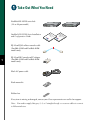
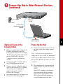
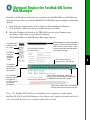
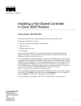
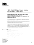
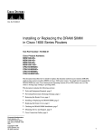
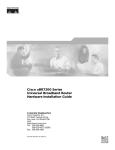
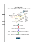
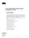
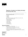
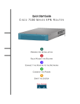
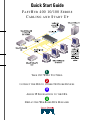
Quick Start Guide
FASTHUB 400 10/100 SERIES
CABLING AND START UP
SERIE
S
1
TAKE OUT WHAT YOU NEED
2
CONNECT THE HUB TO OTHER NETWORK DEVICES
3
ASSIGN IP INFORMATION TO THE HUB
4
DISPLAY THE WEB-BASED HUB MANAGER
Take Out What You Need
FastHub 400 10/100 series hub
(12- or 24-port model)
10BaseT/100BaseTx
10BaseT/100BaseTx
RPS
10 100
1x
RPS
2x
3x
4x
5x
6x
7x
8x
9x
10x
11x
10 100
12x
2x
MODE
3x
4x
5x
6x
7x
8x
9x
10x
11x
12x
13x
14x
15x
16x
17x
18x
19x
20x
21x
22x
23x
24x
24
n
tio on
la ti
al ra
st gu e
In nfi uid
o
C G
rt
ta
S
ck de
ui ui
Q G
FastHub 400 10/100 Series Installation
and Configuration Guide
1x
12
MODE
RJ-45-to-RJ-45 rollover console cable
(FastHub 412M and FastHub 424M
models only)
1
RJ-45-to-DB-9 console-to-PC adapter
(FastHub 412M and FastHub 424M
models only)
Black AC power cable
Rack-mount kit
Rubber feet
If any item is missing or damaged, contact your Cisco representative or reseller for support.
Note: You need to supply Category 3, 4, or 5 straight-through or crossover cables to connect
to Ethernet devices.
Connect the Hub to Other Network Devices
10BaseT/100BaseTx
RPS
10 100
1x
2x
3x
4x
5x
6x
7x
8x
9x
10x
11x
12x
13x
14x
15x
16x
MODE
17x
18x
19x
20x
21x
22x
23x
24x
24
10BaseT/100BaseTX
network port (RJ-45)
Maximum cable length:
328 ft (100 m)
10BaseT or
100BaseTX port
(RJ-45)
Ethernet cable
(not supplied)
2
Note: Use a straight-through cable to
connect two ports when one of the ports is
designated with an X. Use a crossover cable
to connect two ports when both ports are
Connect the Hub to Switches
and Other Hubs
•
Connect a Category 3, 4, or 5 crossover
cable to any 10/100 port on the hub and
to a 10BaseT port on the target switch
or hub.
•
Connect a Category 5 crossover cable to
any 10/100 port on the hub and to a
100BaseTX port on the target switch or
hub.
designated with an X.
Connect the Hub to Servers,
Routers, and Workstations
•
Connect a Category 3, 4, or 5
straight-through cable to any 10/100
port on the hub and to a 10BaseT port
on the workstation, server, or router.
•
Connect a Category 5 straight-through
cable to any 10/100 port on the hub and
to a 100BaseTX port on the
workstation, server, or router.
Connect the Hub to Other Network Devices
(continued)
RATING
100-127 / 200-240 V~
2A /1A 50 / 60 Hz
CONSOLE
UP
DC INPUTS FOR REMOTE
POWER SUPPLY
SPECIFIED IN MANUAL
+5V @6A, +12V @1A
DC INPUT
10/100 BASE-TX
DOWN
MEDIA MODULE
STAT DUP 100
RATING
100-127 / 200-240 V~
2A /1A 50 / 60 Hz
CONSOLE
UP
DC INPUTS FOR REMOTE
POWER SUPPLY
SPECIFIED IN MANUAL
+5V @6A, +12V @1A
DC INPUT
10/100 BASE-TX
STAT DUP 100
DOWN
MEDIA MODULE
RATING
100-127 / 200-240 V~
2A /1A 50 / 60 Hz
CONSOLE
UP
DC INPUTS FOR REMOTE
POWER SUPPLY
SPECIFIED IN MANUAL
+5V @6A, +12V @1A
DC INPUT
100 BASE-FX
LINK DUP
TX
RX
DOWN
MEDIA MODULE
3
(Optional) Install the
Switched Uplink Module in
the Hub
1
2
Power off the hub.
Remove and set aside the screws
attaching the faceplate to expansion slot
on the hub. The screws will be used later
in Step 6.
3
Remove the faceplate from the hub and
store it for future use.
4
Slide the module into the slot
card-guides until you feel it touch the
back of the hub.
5
Push the module firmly until it snaps
into place and is firmly seated.
6
Insert and tighten the screws on the
module faceplate.
7
Power on the hub.
(Optional) Connect to the
Switched Uplink Module
Port
Insert a connector according to the type of
module (10/100 or 100BaseFX), as follows:
•
10BaseT/100BaseTX connector—Insert
the connector until it snaps into place in the
module port.
Note: Use a straight-through cable to
connect two ports when one of the ports is
designated with an X. Use a crossover cable
to connect two ports when both ports are
designated with an X.
•
100BaseFX SC connector—Remove the
rubber plugs from the fiber-optic port
on the module and store them for future
use. Insert the connector in the
fiber-optic module port.
Connect the Hub to Other Network Devices
(continued)
RATING
100-127 / 200-240 V~
2A /1A 50 / 60 Hz
CONSOLE
DC INPUTS FOR REMOTE
POWER SUPPLY
SPECIFIED IN MANUAL
+5V @6A, +12V @1A
UP
DC INPUT
10/100 BASE-TX
STAT DUP 100
DOWN
MEDIA MODULE
Console port
(RJ-45)
Power outlet
RJ-45-to-RJ-45
rollover console cable
(supplied)
RJ-45-to-DB-9
adapter (supplied)
(Optional) Connect the
Console Cable
1
Make sure console port settings of the
FastHub 400M model match the
settings of the terminal, PC, or laptop.
The default settings of the hub console
port are 9600 baud, 8 data bits,
1 stop bit, no parity, and no flow
control.
Power Up the Hub
1
Connect one end of the power cord to
the hub and the other end to a power
source.
Note: You can use the internal power
supply and the Cisco 600W AC Redundant
Power System (RPS). Attach only the Cisco
RPS (model PWR600-AC-RPS) to the RPS
2
Connect the rollover console cable to
the CONSOLE port on the hub.
receptacle.
3
Connect the other end of the rollover
cable to your terminal, PC, or laptop
(if necessary, use an appropriate
adapter, such as the supplied
RJ-45-to-DB-9 adapter).
2
4
From your terminal, PC, or laptop, start
the terminal emulation program.
Wait approximately 2 minutes for the
hub to complete its power-on self-test
(POST).
After POST completes, the Continue
with configuration dialog? prompt
appears on the management station.
You can then follow the prompts to
assign IP information to the hub.
4
(Optional) Assign IP Information to the Hub
The hub is designed to operate with little or
no user intervention. In most cases, you can
use it with its default settings.
Assign IP information to the FastHub 400M
model so that you can use the FastHub 400
series Hub Manager web-based interface
and so that the hub can communicate with
local routers and the intranet.
Contact your system administrator for the
hub IP information, and record it here.
Hub IP address:
4
Enter the IP address of the default
gateway (for example: 10.1.105.254):
Enter IP default gateway: 10.1.105.254
The following information is displayed:
The following configuration command
script was created:
ip address 10.1.105.20 255.255.255.0
ip default-gateway 10.1.105.254
!
end
5
Enter Y:
Use this configuration? Y
Subnet mask:
The following information is displayed:
Default gateway:
5
1
From the terminal or PC, enter Y:
Continue with configuration dialog? Y
2
Enter the IP address (for example:
10.1.105.20):
Enter IP address: 10.1.105.20
3
Enter the subnet mask (IP netmask)
(for example: 255.255.255.0):
Enter IP netmask: 255.255.255.0
Building configuration...
Use the enabled mode ‘configuration’
command to modify this configuration.
Press RETURN to get started.
6
7
Press Return.
Exit from the terminal session.
You can now display the FastHub 400 series
Hub Manager.
(Optional) Display the FastHub 400 Series
Hub Manager
If you have the IP address to the hub, you can display the FastHub 400 series Hub Manager
from your intranet. You can use the FastHub 400 series Hub Manager to configure and monitor
the hub.
1
Start Netscape Communicator (4.03 or higher) or Microsoft Internet Explorer
(4.01 or higher). Make sure that Java and JavaScript are enabled.
2
Enter the IP address of the hub in the URL field if you are using Communicator
(the Address field if you are using Internet Explorer).
The FastHub 400 series Hub Manager Home page appears.
Click Apply after
making changes
on a page.
Click Revert
to discard
unapplied
changes on
a page.
HOME
PORT GROUP IP SNMP CDP SYSTEM
Click these topics to move from page
to page. On Netscape Communicator
only, when the cursor is above a topic,
a pop-up briefly describes the options
on that particular page.
Click a port to display its
settings, status, and statistics.
Click Help for
procedures and
detailed field
descriptions.
Click the Mode
button to change
the mode that
the LEDs display
for the fixed
10/100 ports.
Click to display the settings, status, and
statistics of an installed 10BaseT/100BaseTX
or 100BaseFX switched uplink module.
Shows when another hub is connected to a
stacking connector on the hub rear panel.
Note: The FastHub 400 10/100 Series Installation and Configuration Guide and the
FastHub 400 10/100 series Hub Manager online help provide complete information about the
web console and describe how to configure and monitor the hub.
6
Corporate Headquarters
Cisco Systems, Inc.
170 West Tasman Drive
San Jose, CA 95134-1706
USA
http://www.cisco.com
Tel: 408 526-4000
800 553-NETS (6387)
Fax: 408 526-4100
European Headquarters
Cisco Systems Europe s.a.r.l.
Parc Evolic, Batiment L1/L2
16 Avenue du Quebec
Villebon, BP 706
91961 Courtaboeuf Cedex
France
http://www-europe.cisco.com
Tel: 33 1 6918 61 00
Fax: 33 1 6928 83 26
Americas
Headquarters
Cisco Systems, Inc.
170 West Tasman Drive
San Jose, CA 95134-1706
USA
http://www.cisco.com
Tel: 408 526-7660
Fax: 408 527-0883
Asia Headquarters
Nihon Cisco Systems K.K.
Fuji Building, 9th Floor
3-2-3 Marunouchi
Chiyoda-ku, Tokyo 100
Japan
http://www.cisco.com
Tel: 81 3 5219 6250
Fax: 81 3 5219 6001
Cisco Systems has more than 200 offices in the following countries. Addresses, phone numbers, and fax numbers are listed on the
Cisco Connection Online Web site at http://www.cisco.com.
Argentina
•
England
France
Mexico
•
•
Australia
•
•
Austria
Germany
The Netherlands
South Africa
•
Spain
•
•
•
•
Belgium
Greece
•
Brazil
•
Canada
•
Hungary
•
India
Indonesia
•
New Zealand
Sweden
•
•
Norway
Switzerland
•
•
•
Peru
•
Chile
•
China (PRC)
•
Philippines
Taiwan, ROC
•
Ireland
•
Thailand
•
Poland
•
•
Colombia
Israel
•
•
Italy
Portugal
Turkey
•
•
•
•
Costa Rica
Japan
Russia
•
•
•
Korea
Czech Republic
•
Luxembourg
•
•
Saudi Arabia
United Arab Emirates
•
•
Scotland
United States
•
•
Denmark
Malaysia
Singapore
Venezuela
AccessPath, Any to Any, AtmDirector, the CCIE logo, CD-PAC, Centri, the Cisco Capital logo, CiscoLink, the Cisco Management Connection logo, the Cisco NetWorks logo, the
Cisco Powered Network logo, the Cisco Press logo, the Cisco Technologies logo, ClickStart, ControlStream, DAGAZ, Fast Step, FireRunner, IGX, IOS, JumpStart, Kernel Proxy,
LoopRunner, MGX, Natural Network Viewer, NetRanger, NetRanger Director, NetRanger Sensor, NetSonar, Packet, PIX, Point and Click Internetworking, Policy Builder, Precept,
RouteStream, Secure Script, SMARTnet, SpeedRunner, Stratm, StreamView, The Cell, TrafficDirector, TransPath, ViewRunner, VirtualStream, VlanDirector, Workgroup Director, and
Workgroup Stack are trademarks; Changing the Way We Work, Live, Play, and Learn, Empowering the Internet Generation, The Internet Economy, and The New Internet Economy
are service marks; and BPX, Catalyst, Cisco, Cisco IOS, the Cisco IOS logo, Cisco Systems, the Cisco Systems logo, Enterprise/Solver, EtherChannel, FastHub, ForeSight,
FragmentFree, IP/TV, IPX, LightStream, LightSwitch, MICA, Phase/IP, StrataSphere, StrataView Plus, and SwitchProbe are registered trademarks of Cisco Systems, Inc. in the U.S. and
certain other countries. All other trademarks mentioned in this document are the property of their respective owners. (9811R)
78-5566-01