1
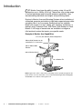
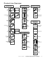
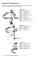
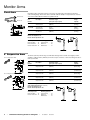
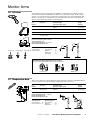
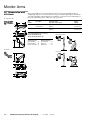
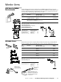
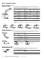
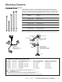
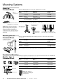
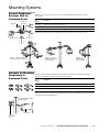
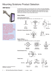
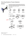
Orderguide
Ergotron
CRT Monitor Arm
Mounting Solutions
®
Ergonomic solutions for any area of your facility
870-03-018, rev. 05/13/04
www.ergotron.com
© 2004 Ergotron, Inc.
Ergotron is a registered trademark of Ergotron, Inc.
Reproduction of this material in whole or in part for any purpose
other than that authorized by Ergotron, Inc. is prohibited.
© 2004 Ergotron, Inc. All rights reserved.
Orderguide
CRT Monitor Arm Mounting Solutions
Table of Contents
Introduction . . . . . . . . .
Product Line Overview
Sample Configurations
Monitor Arms . . . . . . . .
.
.
.
.
.
.
.
.
.
.
.
.
.
.
.
.
.
.
.
.
.
.
.
.
.
.
.
.
Fixed Arms . . . . . . . . . . . . . . . . .
6" Suspension Arms . . . . . . . . . .
10" Lift Arms . . . . . . . . . . . . . . . .
12" Suspension Arms . . . . . . . . .
16" Suspension and Lift Arms . . .
N12 Arm for NEMA Environments
Extender Arms . . . . . . . . . . . . . .
.
.
.
.
.
.
.
.
.
.
.
.
.
.
.
.
.
.
.
.
.
.
.
.
.
.
.
.
.
.
.
.
.
.
.
.
.
.
.
.
.
.
.
.
.
.
.
.
.
.
.
.
.
.
.
.
.
.
.
.
.
.
.
.
.
.
.
.
.
.
.
.
.
.
.
.
.
.
.
.
.
.
.
.
.
.
.
.
.
.
.
.
.
.
.
.
.
.
.
.
.
.
.
.
.
.
.
.
.
.
.
.
.
.
.
.
.
.
.
.
.
.
.
.
.
.
.
.
.
.
.
.
.
.
.
.
.
.
.
.
.
.
.
.
.
.
.
.
.
.
.
.
.
.
.
.
.
.
.
.
.
.
.
.
.
.
.
.
.
.
.
.
.
.
.
.
.
.
.
.
.
.
.
.
.
.
.
.
.
.
.
.
.
.
.
.
.
.
.
.
.
.
.
.
.
.
.
.
.
.
.
.
.
.
.
.
.
.
.
.
.
.
.
.
.
.
.
.
.
.
.
.
.
.
.
.
.
.
.
.
.
.
.
.
.
.
.
.
.
.
.
.
.
.
.
.
.
.
.
.
4
5
6
8
.
.
.
.
.
.
.
.
.
.
.
.
.
.
.
.
.
.
.
.
.
8
8
9
9
10
11
11
Arm Components . . . . . . . . . . . . . . . . . . . . . . . . . . . . . . . . . . 12
Monitor Caddies . . . . . . . . . . . . . . . . . . . . . . . . . . . . . . . . . . . . . . . .
Monitor Platforms . . . . . . . . . . . . . . . . . . . . . . . . . . . . . . . . . . . . . . .
Rotation Control Kit . . . . . . . . . . . . . . . . . . . . . . . . . . . . . . . . . . . . . .
12
12
12
Mounting Systems . . . . . . . . . . . . . . . . . . . . . . . . . . . . . . . . . . 13
Command Posts
Wall Tracks . . . .
Wall Bracket . . .
Desk Mounts . . .
.
.
.
.
.
.
.
.
.
.
.
.
.
.
.
.
.
.
.
.
.
.
.
.
.
.
.
.
.
.
.
.
.
.
.
.
.
.
.
.
.
.
.
.
.
.
.
.
.
.
.
.
.
.
.
.
.
.
.
.
.
.
.
.
.
.
.
.
.
.
.
.
.
.
.
.
.
.
.
.
.
.
.
.
.
.
.
.
.
.
.
.
.
.
.
.
.
.
.
.
.
.
.
.
.
.
.
.
.
.
.
.
.
.
.
.
.
.
.
.
.
.
.
.
.
.
.
.
.
.
.
.
.
.
.
.
.
.
.
.
.
.
.
.
.
.
.
.
.
.
.
.
.
.
.
.
.
.
.
.
13
16
17
17
Keyboard Solutions . . . . . . . . . . . . . . . . . . . . . . . . . . . . . . . . . 18
Keyboard Holders, Trays and Arms . . . . . . . . . . . . . . . . . . . . . . . . . .
18
Peripherals and Accessories . . . . . . . . . . . . . . . . . . . . . . . . . 19
CPU Holders, Shelves and Cabinets
Peripheral Table . . . . . . . . . . . . . . .
Security Straps . . . . . . . . . . . . . . . .
Footrests . . . . . . . . . . . . . . . . . . . .
Cable Management . . . . . . . . . . . . .
Power Strips . . . . . . . . . . . . . . . . . .
.
.
.
.
.
.
.
.
.
.
.
.
.
.
.
.
.
.
.
.
.
.
.
.
.
.
.
.
.
.
.
.
.
.
.
.
.
.
.
.
.
.
.
.
.
.
.
.
.
.
.
.
.
.
.
.
.
.
.
.
.
.
.
.
.
.
.
.
.
.
.
.
.
.
.
.
.
.
.
.
.
.
.
.
.
.
.
.
.
.
.
.
.
.
.
.
.
.
.
.
.
.
.
.
.
.
.
.
.
.
.
.
.
.
.
.
.
.
.
.
.
.
.
.
.
.
.
.
.
.
.
.
.
.
.
.
.
.
.
.
.
.
.
.
.
.
.
.
.
.
19
20
20
21
21
21
Appendix . . . . . . . . . . . . . . . . . . . . . . . . . . . . . . . . . . . . . . . . . 22
Weight Capacity . . . . . . . . . . .
Hole Patterns . . . . . . . . . . . . .
Computer Carts . . . . . . . . . . .
Other Keyboard/Laptop Mounts
Ergonomics Data . . . . . . . . . .
870-03-018
rev. 05/13/04
•
.
.
.
.
.
.
.
.
.
.
.
.
.
.
.
.
.
.
.
.
.
.
.
.
.
.
.
.
.
.
.
.
.
.
.
.
.
.
.
.
.
.
.
.
.
.
.
.
.
.
.
.
.
.
.
.
.
.
.
.
.
.
.
.
.
.
.
.
.
.
.
.
.
.
.
.
.
.
.
.
.
.
.
.
.
.
.
.
.
.
.
.
.
.
.
.
.
.
.
.
.
.
.
.
.
.
.
.
.
.
.
.
.
.
.
.
.
.
.
.
.
.
.
.
.
.
.
.
.
.
.
.
.
.
.
CRT Monitor Mounting Solutions Orderguide
.
.
.
.
.
.
.
.
.
.
22
23
24
25
26
•
3
Introduction
RT Monitor Arms have the ability to swing, rotate, tilt and lift
monitors up to 100 lbs (45.4 kg). These arms offer a wide range
of vertical adjustment and horizontal extension capabilities, thus
accommodating individual user heights and positioning needs.
C
Ergotron’s Monitor Arms and Mounting Systems allow installation of
a complete computer workstation in tight and congested areas while
occupying little or no floor space. Several options are available.
Mount your system to a floor, ceiling, wall, machine, workbench, or
desktop using Command Posts, Wall Tracks, Wall Brackets or Desk
Mounts. A full range of accessories are available to configure a
fully-functional system that meets your specific needs.
Example of Monitor Arm Capabilities
0" to 16" (0 to 406 mm) Vertical Adjustment
Side-to-Side Rotation can be
controlled in 7.5° increments
200° of Side-to-Side
Rotation
360° of Monitor Swivel
20° of Monitor Tilt
Note: Ergotron also offers a wide variety of mounting systems specially designed for flat
panel monitors. For more information, see our Flat Panel Mounting Solutions Orderguide,
#870-03-005 on our website, www.ergotron.com.
4
•
CRT Monitor Mounting Solutions Orderguide
•
rev. 05/13/04
870-03-018
Product Line Overview
Monitor Arms
Mounting Systems
Fixed
Arms
Suspend
Command
Posts
Keyboard
Holders
& Trays
Wall
Tracks
Wrist Rests &
Mouse Pads
Lift
6" Suspension
Arms
13" Horizontal
Keyboard Solutions
19" Horizontal
10" Lift
Arms
Wall
Brackets
12" Suspension
Arms
Desk
Mounts
16"
Arms
Peripherals &
Accessories
CPU Holders
& Cabinets
Worksurfaces
Lift
Arm Components
Suspend
N12 Arms
for NEMA
environments
Monitor
Caddies
Footrests
Extender
Arms
Monitor
Platforms
Cable
Management
Rotation
Control Kits
Security
Straps
Power
Strips
870-03-018
rev. 05/13/04
•
CRT Monitor Mounting Solutions Orderguide
•
5
Sample Configurations
Configure your own customized solutions with Ergotron’s modular components.
Here are some examples of common configurations.
Configuration A
20-078-000
60-138-000
60-155-000
97-095-099
44-316-000
44-308-000
40-004-000
75-055-009
77-050-000
85-033-000
99-033-078
85-025-079
80-061-000
60-159-000
55-035-999
65-048-000
60-159-000
85-023-000
60-159-000
Command Post, 4" x 4" x 96" Post
Base for 4" x 4" Post
Bracket for Arm to 4" x 4" Post
Second Component Fastener Kit
30" Extender Arm
12" Suspension Arm (2)
Monitor Caddy, Type 3 (2)
Adjustable Keyboard Tray Holder (2)
Keyboard Tray w/ Sliding Mouse Tray (2)
Wrist Rest (2)
Mouse Pouch (2)
Mouse Pad (2)
Large Horizontal CPU Holder
Bracket for Peripheral to 4" x 4" Post
Peripheral Table
Fold-Away Underbracing for Peripheral Table
Bracket for Peripheral to 4" x 4" Post
Footrest
Bracket for Peripheral to 4" x 4" Post
Configuration B
20-078-000
60-155-000
44-316-000
44-309-000
40-043-000
44-311-000
33-059-000
75-053-009
Command Post, 4" x 4" x 96" Post
Bracket for Arm to 4" x 4" Post (2)
30" Extender Arm
16" Suspension Arm
Monitor Caddy, Type 3T
20" Fixed Arm without shroud
Monitor Platform
Adjustable Keyboard Holder
Attachment of Post to
machine by customer
Configuration C
Mounts to ceiling
6
•
CRT Monitor Mounting Solutions Orderguide
20-075-000
60-360-000
60-154-000
44-309-000
80-058-000
97-097-099
80-060-000
60-158-000
40-043-000
75-055-009
77-049-000
•
rev. 05/13/04
Command Post, 3" x 3" x 48" Post
Base for 3" x 3" Post
Bracket for Arm to 3" x 3" Post
16" Suspension Arm
Medium Vertical CPU Holder
Second Component Fastener Kit
Medium Horizontal CPU Holder
Bracket for Peripheral to 3" x 3" Post
Monitor Caddy, Type 3T
Adjustable Keyboard Tray Holder
Keyboard Tray
870-03-018
Sample Configurations
Configure your own customized solutions with Ergotron’s modular components.
Here are some examples of common configurations.
Configuration D
31-018-182
44-314-000
60-188-099
44-303-000
40-004-000
80-058-000
60-156
55-035-999
65-048-000
60-156
Wall Track, 34"L
18" Extender Arm
Bracket for Arm to Wall Track
6" x 13" “B” Suspension Arm
Monitor Caddy, Type 3
Medium Vertical CPU Holder
Bracket for Peripheral to Wall Track
Peripheral Table
Fold-Away Underbracing for Peripheral Table
Bracket for Peripheral to Wall Track
Configuration E
31-018-182
44-309-000
60-151-099
40-004-000
75-055-009
77-050-000
85-010-087
99-033-078
85-025-079
80-062-000
60-156
Wall Track, 34"L
16" Suspension Arm
Bracket for Arm to Wall Track
Monitor Caddy, Type 3
Adjustable Keyboard Tray Holder
Keyboard Tray w/ Sliding Mouse Tray
Wrist Rest
Mouse Pouch
Mouse Pad
CPU Cabinet
Bracket for Peripheral to Wall Track
Configuration F
31-017-182
44-307-000
60-151-099
33-004-000
75-055-009
77-050-000
85-010-087
99-033-078
85-025-079
Wall Track, 26"L
16" Lift Arm
Bracket for Arm to Wall Track
Monitor Platform for 16" Lift Arm
Adjustable Keyboard Tray Holder
Keyboard Tray w/ Sliding Mouse Tray
Wrist Rest
Mouse Pouch
Mouse Pad
Configuration G
60-152-000
44-316-000
44-309-000
40-004-000
Wall Mounting Bracket
30" Extender Arm
16" Suspension Arm
Monitor Caddy, Type 3
Configuration H
33-269-000
44-343-000
75-038
77-026-098
85-008-098
85-025-079
Grommet Mount
10" Lift Arm
Articulating Keyboard Arm
Keyboard Tray w/ Sliding Mouse Tray
Wrist Rest for Articulating Arm
Mouse Pad
870-03-018
rev. 05/13/04
•
CRT Monitor Mounting Solutions Orderguide
•
7
Monitor Arms
Fixed Arms
Fixed Arms swing, and rotate monitors to the point of need. Their tilt control extends a monitor’s
vertical viewing range. These arms can be used with a Monitor Caddy in a suspend mode, or turned
over and used with a Monitor Platform in a platform mode.
Without Shroud
With Shroud
2.75
Part
Number
Description
Horizontal Length
(pivot point to pivot point)
Weight
Capacity
44-311-000
20" Fixed Arm
without Shroud
20"
(508 mm)
100 lbs
(45.4 kg)
44-312-000
13" Fixed Arm
without Shroud
12-3/4"
(324 mm)
100 lbs
(45.4 kg)
44-313-000
20" Fixed Arm
with Shroud
20"
(508 mm)
100 lbs
(45.4 kg)
22.75
1.68
20.00
5.23
5.64
7
2.00
1.75
14.5
1.68
12.75
5.23
5.79
7.63
2.00
Side-to-Side Range: 200°
Monitor Tilt Adjustment: 20°
Monitor Swivel Adjustment: 360°
6" Suspension Arms
6" x 13" Suspension Arms
Arm Components:
Mounting Systems:
Monitor Caddies . . . .12
Monitor Platforms . . .12
Rotation Control Kit . .12
Command Post . . . . .13
Wall Track . . . . . . . . .16
Wall Bracket . . . . . . .17
The 6-inch (152 mm) vertical range accommodates average male to female user heights (in either
standing or sitting positions). Extend your monitor out up to 13 inches or 19 inches. Swing, tilt, raise or
rotate your monitor.
15.46
12.71
2.75
4.34
7.10
7.68
13.11
10.36
12.96
Part
Number
Description
Horizontal Length
(pivot point to pivot point)
Weight
Capacity
44-302-000
6" x 13" “A”
Suspension Arm
12-3/4"
(324 mm)
15-35 lbs
(6.8-15.9 kg)
44-303-000
6" x 13" “B”
Suspension Arm
12-3/4"
(324 mm)
35-65 lbs
(15.9-29.5 kg)
44-304-000
6" x 19" “A”
Suspension Arm
18-3/4"
(476 mm)
15-35 lbs
(6.8-15.9 kg)
44-305-000
6" x 19" “B”
Suspension Arm
18-3/4"
(476 mm)
35-65 lbs
(15.9-29.5 kg)
44-306-000
6" x 19" “C”
Suspension Arm
18-3/4"
(476 mm)
65-100 lbs
(29.5-45.4 kg)
13.54
6" x 19" Suspension Arms
21.46
18.71
2.75
4.34
7.10
7.68
19.11
16.36
12.96
13.54
8
•
Side-to-Side Range: 200°
Vertical Adjustment Range: 6" (152 mm)
Monitor Tilt Adjustment: 20°
Monitor Swivel Adjustment: 360°
Arm Components:
Mounting Systems:
Monitor Caddies . . . .12
Rotation Control Kit . .12
Command Post . . . . .13
Wall Track . . . . . . . . .16
Wall Bracket . . . . . . .17
CRT Monitor Mounting Solutions Orderguide
•
rev. 05/13/04
870-03-018
Monitor Arms
10" Lift Arm
This versatile arm offers lift, swing and rotate capabilities. It adjusts 10 inches (254 mm) vertically.
Includes Monitor Platform and Quick-Release Tabs to secure the monitor in place. Mount to vertical
surfaces or to horizontal surfaces. If mounting to a horizontal surface, choose the Desk Clamp, which
attaches to an edge up to 3" (76 mm) thick, or the Grommet Mount, which attaches through a hole
3/8" to 3" (10 to 76 mm) wide and up to 4" (102 mm) thick.
16.5"
17.75"
Part
Number
Description
Horizontal Length
(pivot point to pivot point)
Weight
Capacity
44-343-000
10" Lift Arm
16"
(406 mm)
20-60 lbs
(9.1-27.2 kg)
60-257-000
Desk Clamp
33-269-000
Grommet Mount
60-378-000
Vertical Mount
(see figure below)
Note: If mounting to a vertical surface, Vertical Mount required. If mounting to horizontal surface, Desk Clamp or
Grommet Mount required. Order separately.
16"
6.5"
Side-to-Side Range: 360°
Vertical Adjustment Range: 10" (254 mm)
Monitor Swivel Adjustment: 360°
21.75"
Arm Components:
Desk Clamp
Vertical Mount Monitor Platform
included with Arm
Grommet Mount
Mounting Systems:
Command Post
Wall Track . . . .
Wall Bracket . .
Desk Mounts .
.
.
.
.
.
.
.
.
.
.
.
.
.
.
.
.
.13
.16
.17
.17
Figure: Vertical Mount Attachment for 10" Lift Arms
Use Vertical Mount #60-378-000 in tandem with Mounting Systems.
Command Post
12" Suspension Arm
25.47
2.75
22.72
4.34
7.72
Wall Track
Wall Bracket
Twelve inches (305 mm) of vertical adjustment provides limited sit-to-stand user adjustability. Extend a
monitor out up to 22 inches (559 mm). Raise, swing, tilt and rotate your monitor.
Part
Number
Description
Horizontal Length
(pivot point to pivot point)
Weight
Capacity
44-308-000
12" Suspension Arm
without Shroud
22-3/4"
(578 mm)
25-100 lbs
(11.4-45.4 kg)
21.40
17.65
Side-to-Side Range: 200°
Vertical Adjustment Range: 12" (305 mm)
Monitor Tilt Adjustment: 20°
Monitor Swivel Adjustment: 360°
19.95
Arm Components:
Mounting Systems:
Monitor Caddies . . . .12
Rotation Control Kit . .12
Command Post . . . . .13
Wall Track . . . . . . . . .16
Wall Bracket . . . . . . .17
870-03-018
rev. 05/13/04
•
CRT Monitor Mounting Solutions Orderguide
•
9
Monitor Arms
16" Suspension and
Lift Arms
Sixteen inches (406 mm) of vertical movement provides true ergonomic adjustability in sitting or
standing applications. It even accommodates the average sit-to-stand height-range. This arm features
clean styling and built-in cable management. It’s available as a suspension arm (use with Caddy) or a
lift arm (use with Platform). Raise, swing, tilt or rotate your monitor.
16" Suspension Arm
24.76
21.69
4.06
Part
Number
Description
Horizontal Length
(pivot point to pivot point)
Weight
Capacity
44-309-000
16" Suspension Arm
without Shroud
22-1/4"
(565 mm)
25-100 lbs
(11.4-45.4 kg)
44-307-000
16" Lift Arm
22-1/4"
(565 mm)
25-100 lbs
(11.4-45.4 kg)
1.50
25.35
3.07
22.28
Side-to-Side Range: 200°
Vertical Adjustment Range: 16" (406 mm)
Monitor Tilt Adjustment: 20°
Monitor Swivel Adjustment: 360°
6.41
8.91
16" Suspension Arm
21.30
18.23
20.50
21.08
Arm Components:
Mounting Systems:
Monitor Caddies . . . .12
Monitor Platforms . . .12
Rotation Control Kit . .12
Command Post . . . . .13
Wall Track . . . . . . . . .16
Wall Bracket . . . . . . .17
16" Lift Arm
16" Lift Arm
14.80
20.25
18.03
21.10
10.71
9.17
6.41
22.28
25.35
2.0
9.25
4.6
21.69
24.76
10
•
CRT Monitor Mounting Solutions Orderguide
•
rev. 05/13/04
870-03-018
Monitor Arms
N12 Arm for NEMA
Environments
The N12 Suspension Arm meets UL requirements for the NEMA standard, allowing you to mount
enclosures in NEMA 12 environments. Features include 16 inches (406 mm) of vertical adjustment and
hassle-free cable management. An integrated quick-connect tube offers an industry proven universal
connection interface while allowing continuous isolation of cables.
Part
Number
Description
Horizontal Length
(pivot point to pivot point)
Weight
Capacity
44-360-000
N12 Suspension Arm
for NEMA environments
22-1/4"
(565 mm)
25-100 lbs
(11.4-45.4 kg)
97-179-098
Cable Routing Tube for N12
Suspension Arm, 1 foot (305 mm),
black, (order in 1-foot increments, minimum 5 feet)
21.69"
24.76"
7.10"
Note: Monitor enclosure not included with N12 Suspension Arm.
Note: Cable Routing Tube for N12 Suspension Arm ordered separately.
25.35"
Side-to-Side Range: 200°
Vertical Adjustment Range: 16" (406 mm)
Monitor Tilt Adjustment: 20°
Monitor Swivel Adjustment: 360°
22.28"
3.07"
6.41"
8.88"
21.30"
18.23"
Arm Components:
Mounting Systems:
Rotation Control Kit . .12
Compatible with 3rdparty monitor enclosures
Command Post . . . . .13
Wall Track . . . . . . . . .16
Wall Bracket . . . . . . .17
20.06"
Extender Arms
Extender Arms can be used in conjunction with all vertical-mount monitor arms, providing additional
placement capabilities. Dual arm adjustability allows monitor positioning at multiple points of use.
Cable Channel
included
2.69
2.75
12.00
Part
Number
Description
Horizontal Length
(pivot point to pivot point)
Weight
Capacity
44-362-000
12" Extender Arm
12"
(305 mm)
see table on
pg. 22
44-314-000
18" Extender Arm
18"
(457 mm)
see table on
pg. 22
44-315-000
24" Extender Arm
24"
(610 mm)
see table on
pg. 22
44-316-000
30" Extender Arm
30"
(762 mm)
see table on
pg. 22
7.70
2.69
2.75
18.00
7.70
2.69
24.00
2.75
Note: When mounting to Command Post, use with 4" x 4" Post only.
Note: Refer to page 22 for detailed information regarding weight capacities.
7.70
2.69
30.00
2.75
12", 18", 24", 30"
Side-to-Side Range: 200°
7.70
Arm Components:
Mounting Systems:
Rotation Control Kit . .12
Command Post . . . . .13
Wall Track . . . . . . . . .16
Wall Bracket . . . . . . .17
Multiple rotation
points give greater
range for positioning
Top View
Command Post
Wall Track
Wall Bracket
A monitor arm attaches to an
Extender Arm, which connects to
Command Post or Wall Track via
a bracket. Wall Bracket requires
no extra bracket
870-03-018
rev. 05/13/04
•
CRT Monitor Mounting Solutions Orderguide
•
11
Arm Components
Monitor Caddies
Monitor Caddies are used in conjunction with Suspension and Fixed Arms. A monitor is securely
cradled within the Caddy. Choose a Caddy appropriate to your monitor’s size. The Caddy’s telescoping
frame further adjusts to an individual monitor’s height.
Part
Number
Description
Height
Adjustment
Monitor
Depth*
Monitor
Width*
Weight
Capacity*
40-002-000
Type 2
Monitor Caddy
12"–15-1/2"
(305–394 mm)
16-1/2"
(419 mm)
—
40 lbs
(18.2 kg)
40-004-000
Type 3
Monitor Caddy
13-1/2"–18-1/2"
(343–470 mm)
19"
(483 mm)
—
65 lbs
(29.5 kg)
40-043-000
Type 3T
Monitor Caddy
13"–18-1/2"
(330–470 mm)
—
13-7/8"**
(352 mm)
70 lbs
(31.8 kg)
40-008-000
Type 4
Monitor Caddy
16-1/2"–22"
(419–559 mm)
22"
(559 mm)
—
70 lbs
(31.8 kg)
40-013-000
Type 5
Monitor Caddy
16-1/2"–22"
(419–559 mm)
—
16-1/4"***
(413 mm)
120 lbs
(54.5 kg)
* Monitor depth, width and weight specifications are listed as maximum measurements.
** For wide-backed monitors; maximum rear monitor width is 13-7/8" (352 mm), measured 13" (330 mm) from front
of monitor.
*** For wide-backed monitors; maximum rear monitor width is 16-1/4" (413 mm), measured 15" (381 mm) from front
of monitor.
Type 3T
Type 3
Type 2
12"–15.5"
14.75"
12"
14"
13.5"–18.5"
17.5"
13"–18.5"
16.50"–22"
13"
12"
Type 5
Type 4
19"
13.75"
16.375"
13.75"
16"
Monitor Platforms
97-053-002
12
•
16"
Monitor Platforms are used with 16" Lift and Fixed Arms. Straps are included to secure the monitor in
place—order polyurethane for easy cleaning. Part number 33-004-000 features a bottom-mounted
handle that is specially suited to the 16" Lift Arm.
Part
Number
Description
Dimensions
33-004-000
Platform w/ polyurethane
straps for 16" Lift Arm
14" x 14"
(356 x 356 mm)
33-056-000
Platform w/ polyurethane
straps for Fixed Arms
14" x 14"
(356 x 356 mm)
33-059-000
Platform w/ nylon straps
for Fixed Arms
14" x 14"
(356 x 356 mm)
33-004-000 Platform for Lift Arm
(includes bottom handle)
Rotation Control Kit
16.50"–22"
33-056-000 Platform for Fixed Arms
(includes front handle)
The optional Rotation Control Kit limits the rotation of a monitor arm. This allows the setting of a
specific rotation range according to your application. Rotation in both directions is set in 7.5°
increments using a standard 5/32" Allen wrench.
Part
Number
Description
Adjustment
Increments
97-053-002
Arm Rotation Control Kit
7.5° increments
CRT Monitor Mounting Solutions Orderguide
•
rev. 05/13/04
870-03-018
Mounting Systems
Command Posts
The Command Post uses little or no floor space. Attach to the floor, suspend from the ceiling, or
clamp to a machine or workbench (choose appropriate mounting hardware from the table below).
It provides one standard interface that will mount multiple components. Choose a length of post that
accommodates your monitor requirements and the size/number of components you wish to mount.
Brackets are required to mount arms and peripherals to post unless noted otherwise (pgs. 14 & 15).
Part
Number
Description
Dimensions
H xW x D
20-143-000*
Post, 2" x 2" x 74"
11-gauge steel wall
74" x 2" x 2"
(1880 x 51 x 51 mm)
20-075-000
Post, 3" x 3" x 48"
11-gauge steel wall
48" x 3" x 3"
(1219 x 76 x 76 mm)
20-076-000
Post, 3" x 3" x 80"
11-gauge steel wall
80" x 3" x 3"
(2032 x 76 x 76 mm)
20-077-000
Post, 3" x 3" x 96"
11-gauge steel wall
96" x 3" x 3"
(2438 x 76 x 76 mm)
20-078-000**
Post, 4" x 4" x 96"
3/16-gauge steel wall
96" x 4" x 4"
(2438 x 102 x 102 mm)
Note: Posts have cable routing access holes to allow cables to pass through them.
Note: Other post lengths can be ordered on a custom basis. Contact your sales representative for more information.
Note: See Mounting Options and Uses Table below to determine which post, base/mounting kit and arm(s) to choose.
Suspension Arm
CPU Holder
Monitor Caddy
Bracket for mounting
arm and peripheral
to post
Top View
Keyboard Holder
and Tray
Multiple arms and
extenders can be mounted
to Command Post***
Command Post
configuration example
Base
Command Post Mounting Options Table
Post P/N
H xW xD
Base / Mounting Kit (page 14)
Floor / Ceiling Mount
Machine / Bench Mount
20-143-000
74" x 2" x 2"
97-012-000
Not recommended*
Arm w/out Ext
20-075-000
48" x 3" x 3"
60-360-000 or 97-011-000
Arm w/out Ext
Arm w/out Ext
20-076-000
80" x 3" x 3"
60-360-000 or 97-011-000
Arm w/out Ext
Arm w/out Ext
20-077-000
96" x 3" x 3"
60-360-000 or 97-011-000
Arm w/out Ext
Arm w/out Ext
20-078-000**
96" x 4" x 4"
60-138-000**
Arm(s) with Ext(s)
Arm(s) with Ext(s)***
Arm = Suspension, Lift or Fixed Arm for CRT monitor (pages 8–11)
Ext = Extender Arm (page 11)
* The 2" x 2" Post should not be mounted to floor or ceiling in applications using CRT Monitor Arms.
** When mounting 4" x 4" Post to machine or bench, fasteners to be supplied by customer.
*** 4" x 4" Post should be employed in applications using Extender Arms, multiple arms, and/or with heavy loads.
870-03-018
rev. 05/13/04
•
CRT Monitor Mounting Solutions Orderguide
•
13
Mounting Systems
Bases for
Command Posts
Base for
Command Post
90-018, Hardware Kit for Base for
attaching base to concrete surface
Caution: Surface construction varies and the
ultimate mounting method you use to attach an
Ergotron mounting system is out of Ergotron’s
control. It is important to consult with the
appropriate local engineering, architectural, or
construction personnel to ensure that an Ergotron
mounting system is mounted properly to handle
applied loads.
Mounting Kits for
Command Posts
Mounting Kit for attaching
post to vertical surface
Select the appropriate Base for your post when mounting to floor or ceiling.
Part
Number
Description
Dimensions
H xW x D
Compatible with
Post(s)…
60-360-000
Base, for
3" x 3" Post
7" x 17" x 17"
(178 x 432 x 432 mm)
20-075-000, 20-076-000
20-077-000
60-138-000
Base, for
4" x 4" Post
8" x 18" x 18"
(203 x 457 x 457 mm)
20-078-000
90-018
Hardware Kit for Base
(4) concrete stud anchors
3/8" dia. x 3-3/4" long
(9.5 x 95 mm)
Note: Mounting 2" x 2" Post to floor or ceiling is not recommended in applications using CRT Monitor Arms.
Note: Order the Hardware Kit for Base when attaching to a concrete surface.
Base upside down for
ceiling application
Base shown in floor
mount application
Base can be
mounted at any
height on Post
Customer provided threaded rod used to
anchor Base above or below a false ceiling
Select the appropriate Mounting Kit when mounting your post to a vertical surface, like a machine
or workbench.
Part
Number
Description
Compatible with
Post(s)…
97-012-000
Mounting Kit, for
2" x 2" Post
20-143-000
97-011-000
Mounting Kit, for
3" x 3" Post
20-075-000, 20-076-000
20-077-000
Note: If mounting 4" x 4" Post to a vertical surface, fasteners to be supplied by customer.
Brackets for Mounting
Monitor Arms to
Command Posts
4" x 4" Post
Brackets are required for mounting monitor arms to posts. All vertical-mount arms are compatible with
these brackets. Order brackets according to post size.
Part
Number
Description
Dimensions
WxH
Arm Mounting
Hardware included…
60-153-000
Bracket for Arm,
2" x 2" Post
4-5/8" x 6-1/2"
(117 x 165 mm)
(4) 3/8"–16 x 3/4"
flat socket head
60-154-000
Bracket for Arm,
3" x 3" Post
5-3/4" x 5-3/8"
(146 x 137 mm)
(4) 3/8"–16 x 3/4"
flat socket head
60-155-000
Bracket for Arm,
4" x 4" Post
6-7/8" x 6-3/8"
(175 x 162 mm)
(6) 3/8"–16 x 3/4"
flat socket head
60-155-000
Extender Arm
14
•
Multiple arms, extenders or
components can be mounted to
Command Post by stacking and
offsetting brackets
CRT Monitor Mounting Solutions Orderguide
•
rev. 05/13/04
870-03-018
Mounting Systems
Second Component
Fastener Kits for
Command Posts
97-097-099
Bracket for
Arm to Post
Mount a second component to the 3" x 3" or 4" x 4" Post Brackets by ordering one of these
Fastener Kits.
Part
Number
Description
97-095-099
Fastener Kit, Suspension, Lift or Fixed Arm
97-096-099
Fastener Kit, Extender Arm
97-097-099
Fastener Kit, CPU Holder
Note: When mounting Extender Arm or multiple monitor arms to Command Post, use 4" x 4" Post only.
Suspension Arm
CPU Holder
Example of multiple Suspension
Arms mounted using 97-095-099
Brackets for Mounting
Peripherals to
Command Posts
Example of multiple
Extender Arms mounted
using 97-096-099
Example of CPU
Holder mounted
using 97-097-099
Peripherals require a bracket (unless noted otherwise) for mounting to a Command Post. Order
brackets according to the post size to which you are mounting.
Part
Number
Description
60-157-000
Bracket for Peripheral, 2" x 2" Post
60-158-000
Bracket for Peripheral, 3" x 3" Post
60-159-000
Bracket for Peripheral, 4" x 4" Post
Note: See the selection of available peripherals on pages 19–21.
Note: If you plan to mount a monitor arm and peripheral on the same bracket, order Bracket for Arm to Post (previous
page) and Fastener Kit #97-097-099 (above).
Install peripherals at any
height on post
CPU Holder
Bracket for
Peripheral to
Post
870-03-018
rev. 05/13/04
•
CRT Monitor Mounting Solutions Orderguide
•
15
Mounting Systems
Wall Tracks
60-151-099
60-188-099
The Wall Track mounting system is a flexible, low-cost mounting method that occupies zero floor space.
This system attaches to most vertical surfaces – such as walls, pillars, and machines – and provides
one standard interface that will mount multiple Ergotron components anywhere along its length.
Choose a length of Wall Track that will accommodate the size and number of components you
wish to mount.
60-156
60-151-099,
Bracket for
Arm to Wall
Track
Part
Number
Description
Dimensions
H xW
31-016-182
10" Wall Track
10" x 5"
(254 x 127 mm)
31-017-182
26" Wall Track
26" x 5"
(660 x 127 mm)
31-018-182
34" Wall Track
34" x 5"
(864 x 127 mm)
31-019-182
50" Wall Track
50" x 5"
(1270 x 127 mm)
Wall Track Mounting Kits
Application…
90-010
Wall Track Mounting Kit (10) Phillips
self-tapping 14 x 1.5 LG screw
Sheet metal or
wood studs
90-011
Wall Track Mounting Kit (10) Phillips
1/4"-20 x 1.5 LG screw/toggle anchor
Hollow walls
Track Mount Bracket Kits
Mounting Screws
60-151-099
Bracket for Suspension, Lift,
Fixed Arm to Wall Track
(4) 3/8"-16 x .75"
hex head screws
60-188-099
Bracket for Extender Arm
to Wall Track
(4) 3/8"-16 x .75"
hex head screws
60-156
Bracket for Peripheral
to Wall Track
(4) 3/8"-16 x .63"
button head screws
Note: See the selection of available peripherals on pages 19–21.
Suspension Arm
Wall Track
CPU Cabinet
Caution: Surface construction varies and the
ultimate mounting method you use to attach an
Ergotron mounting system is out of Ergotron’s
control. It is important to consult with the
appropriate local engineering, architectural, or
construction personnel to ensure that an Ergotron
mounting system is mounted properly to handle
applied loads.
Suspension Arm
Wall Track
configuration
example
Monitor Caddy
Keyboard Holder
and Tray
16
•
CRT Monitor Mounting Solutions Orderguide
•
rev. 05/13/04
870-03-018
Mounting Systems
Wall Bracket
The Wall Bracket allows mounting of any monitor arm directly to a wall or solid structure, like a
machine or pillar. This economical solution adds the extra support you need.
Part
Number
Description
Dimensions
WxH
Arm Fasteners
60-152-000
Wall Mounting Bracket
with arm fasteners
6-5/8" x 8"
(168 x 203 mm)
(6) 3/8"-16 x 3/4"
carriage bolt
Note: Fasteners that attach Wall Bracket to wall are not supplied by Ergotron.
Wall Bracket
Caution: Surface construction varies and the
ultimate mounting method you use to attach an
Ergotron mounting system is out of Ergotron’s
control. It is important to consult with the
appropriate local engineering, architectural, or
construction personnel to ensure that an Ergotron
mounting system is mounted properly to handle
applied loads.
Desk Mounts
Desk Clamp
Fasteners that attach
bracket to wall not
included
Extender Arm
Desk Mounts allow direct attachment of a monitor arm to a horizontal surface, like a tabletop or desk.
They are compatible only with the 10" Lift Arm.
Grommet Mount
Part
Number
Description
Attaches to…
60-257-100
Desk Clamp
Horizontal surface at edge ≤ 3" (76 mm) thick
33-269-000
Grommet Mount
Horizontal surface through hole 3/8" to 3"
(10 to 76 mm) wide, up to 4" (102 mm) thick
Keyboard Holder
10" Lift Arm
Desk Clamp
870-03-018
Desk Mount
configuration
example
rev. 05/13/04
•
CRT Monitor Mounting Solutions Orderguide
•
17
Keyboard Solutions
Keyboard Holders,
Trays & Arms
75-052-009
Wire Keyboard Holders: Store your keyboard out of the way, then pull it out when needed. Tilt up or
down in 15˚ increments. Keyboard Holders mount under Caddies and Platforms.
Part
Number
Description
Dimensions
WxDxH
Weight
Capacity
75-052-009
Wire Keyboard Holder
2" drop, pull-out
12-7/8" x 23-1/2" x 4-1/2"
(327 x 597 x 114 mm)
15 lbs
(6.8 kg)
75-053-009
Wire Keyboard Holder
4" drop, pull-out
12-7/8" x 23-1/2" x 6-1/2"
(327 x 597 x 165 mm)
15 lbs
(6.8 kg)
75-064-009
Wire Keyboard Holder
2" drop, pull-out
(10" Lift Arm only)
12-7/8" x 23-1/2" x 4-1/2"
(327 x 597 x 114 mm)
15 lbs
(6.8 kg)
75-065-009
Wire Keyboard Holder
4" drop, pull-out
(10" Lift Arm only)
12-7/8" x 23-1/2" x 6-1/2"
(327 x 597 x 165 mm)
15 lbs
(6.8 kg)
75-053-009
75-054-009
75-055-009
77-049-000
Adjustable Keyboard Tray Holders: Store your keyboard out of the way, then pull it out when needed.
Tilt up or down in 15˚ increments. Keyboard Holders mount under Caddies and Platforms. Use with
separately ordered Keyboard/Mouse Trays (see below).
75-054-009
Adj. Keyboard Tray Holder
2.5" drop, pull-out
12-7/8" x 18-3/8" x 4"
(327 x 467 x 102 mm)
15 lbs
(6.8 kg)
75-055-009
Adj. Keyboard Tray Holder
5" drop, pull-out
12-7/8" x 18-3/8" x 7-1/2"
(327 x 467 x 191 mm)
15 lbs
(6.8 kg)
77-050-000
Keyboard/Mouse Trays Accessories: Use with the Adjustable Keyboard Tray Holders (see above).
Use with…
85-014-000
77-001-000
Steel Keyboard/Mouse Tray 26" x 8-1/4"
(660 x 210 mm)
75-052, 75-053
75-064 or 75-065
77-049-000
Keyboard Tray
16-1/2" x 7-1/4" x 2"
(419 x 184 x 51 mm)
75-054-009 or
75-055-009
77-050-000
Keyboard Tray w/ Sliding
Mouse Tray & Wrist Rest
Holder
17-1/2" x 9 to 12" x 2-1/2"
(445 x 229 to 305 x 64 mm)
75-054-009 or
75-055-009
77-076-000
Keyboard Tray w/ Handle
and Sliding Mouse Tray
17-1/2" x 12-1/2" x 3-3/8"
(445 x 318 x 86 mm)
75-054-009 or
75-055-009
85-014-000
Front Mouse Tray
7-1/4" x 7-1/8" x 1"
(184 x 181 x 25 mm)
77-049-000
85-024-000*
Sliding Mouse Tray and
Wrist Rest Holder
85-033
Wrist Rest, black
19" x 3" (483 x 76 mm)
85-010-087
Wrist Rest, grey,
premium, easy-clean
19" x 3"
(483 x 76 mm)
85-025-079
Mouse Pad
7" x 7" (178 x 178 mm)
99-033-078
Mouse Pouch, grey
77-076-000
85-024-000
85-033-000
Wrist Rest
85-025-079
Mouse Pad
99-033-078
Mouse Pouch
77-049-000
* 85-024-000 converts 77-049-000 into 77-050-000.
Articulating Keyboard Arms & Tray: Mount this arm under almost any worksurface or desktop.
Features wide-ranging adjustment: slide forward and back, move up and down 6 inches, rotate 360°,
tilt tray to fore and aft. Very smooth motion and durable construction. Color is black.
Articulating Keyboard Arm, Keyboard Tray w/
Sliding Mouse Tray, and Wrist Rest
Note: See page 25 for information regarding other
keyboard mounts.
18
•
75-038
Articulating Keyboard Arm
L = 16-7/8" (427 mm) – stored position
77-026-098
Keyboard Tray with Sliding
Mouse Tray
21" x 10-1/2" x 1-1/2"
(533 x 267 x 38 mm)
85-008-098
Wrist Rest for
Articulating Arm
19-1/2" x 2"
(495 x 51 mm)
85-016-087
Wrist Rest for Art. Arm,
grey, premium, easy-clean
19-1/2" x 2"
(495 x 51 mm)
CRT Monitor Mounting Solutions Orderguide
•
rev. 05/13/04
870-03-018
Peripherals and Accessories
CPU Holders, Shelves
and Cabinets
80-063-000
Small CPU Holder
80-058-000
Medium CPU Holder
80-059-000
Large CPU Holder
CPU Holders: Mount CPUs in a vertical, tower position. Each holder’s width is adjustable. Three sizes
are available to accommodate equipment 1-3/8" to 10-3/4" wide. Mount to Command Post, Wall Track,
or directly to a vertical surface.
Part
Number
Description
Dimensions
H x W x D (D = Adjustment Range)
Weight
Capacity
80-063-000
CPU Holder,
Small
6" x 10" x 1-3/8–3-3/4"
(152 x 254 x 35–95 mm)
50 lbs
(22.7 kg)
80-058-000
CPU Holder,
Medium
6-1/2" x 10" x 3-3/8–7-5/8"
(165 x 254 x 86–194 mm)
100 lbs
(45.4 kg)
80-059-000
CPU Holder,
Large
14-5/8" x 12" x 5–10-3/4"
(371 x 305 x 127–273 mm)
150 lbs
(68.1 kg)
Note: When mounting to a Command Post or Wall Track, bracket is required. See pages 15–16.
Note: When mounting directly to surface, fasteners are supplied by user.
CPU Shelves: CPU Shelves are available in two sizes. They provide greater surface area to place
equipment. Mount to Command Post, Wall Track, or directly to a vertical surface. Cables are routed
through a back opening.
80-060-000
Medium CPU
Shelf
80-061-000 Large
CPU Shelf
80-060-000
CPU Shelf,
Medium
17" x 17" x 5"
(432 x 432 x 127 mm)
100 lbs
(45.4 kg)
80-061-000*
CPU Shelf,
Large
22" x 20" x 7-1/2"
(559 x 508 x 191 mm)
150 lbs
(68.1 kg)
* Do not use CPU Shelf, Large (80-061-000) with the 2" x 2" Command Post (20-143-000).
Note: When mounting to a Command Post or Wall Track, bracket is required. See pages 15–16.
Note: When mounting directly to surface, fasteners are supplied by user.
CPU Cabinet: Ergotron’s CPU Cabinet provides a secure enclosure to mount and protect equipment
up to 18-3/8" wide. It secures with a lockable, hinged front panel and lockable, removable back panel.
The bottom and back are vented. Cables pass through routing holes in the bottom.
80-062-000 CPU
Cabinet
80-062-000
CPU Cabinet
18-3/8" x 21" x 8"
(467 x 533 x 203 mm)
65-029-000
Fixed Underbracing for horizontal mounting to
3" x 3" Command Post
65-088-000
Fixed Underbracing for horizontal mounting to
4" x 4" Command Post
65-059-000
Fixed Underbracing for horizontal mounting to
Wall Track
125 lbs
(56.7 kg)
Note: To mount CPU Cabinet vertically on Command Post or Wall Track, bracket is required. See pages 15–16.
Note: To mount CPU Cabinet horizontally on Command Post or Wall Track, order appropriate Fixed Underbracing
above. No extra bracket is required.
CPU Cabinet in horizontal position
with back cover removed
Bracket is required when
mounting holder to Command
Post or Wall Track
870-03-018
rev. 05/13/04
•
CRT Monitor Mounting Solutions Orderguide
•
19
Peripherals and Accessories
Peripheral Table
Fold-Away Underbracing and Peripheral
Table shown in up position (above) and
down position (below)
The Peripheral Table provides a solid, laminated surface for writing or holding equipment. Comes in
Grey Millstone finish. Configure it with either a Fixed or Fold-Away Underbracing. Mount to Command
Post, Wall Track, or directly to a vertical surface.
Part
Number
Description
Dimensions
WxDxH
55-035-999
Peripheral Table,
laminated
20" x 18" x 3/4"
(508 x 457 x 19 mm)
65-048-000
Fold-Away Underbracing
65-029-000
Fixed Underbracing for horizontal mounting to
3" x 3" Command Post
65-088-000
Fixed Underbracing for horizontal mounting to
4" x 4" Command Post
65-059-000
Fixed Underbracing for horizontal mounting to
Wall Track
Note: When mounting directly to surface, fasteners are supplied by user.
Note: To mount Fold-Away Underbracing to Command Post or Wall Track, bracket is required. See pages 15–16.
Note: No extra bracket is required for Fixed Underbracing.
55-035-999 Peripheral Table
with laminated worksurface
Security Straps
65-048-000 FoldAway Underbracing
65-029-000 Fixed
Underbracing for
3" x 3" Post
Ergolock Kits are used to further secure equipment. Depending on your application, choose from either
the Strap with Buckle Kits or the Locking Strap with Fastener Kits.
Part
Number
Description
Includes…
Weight
Capacity
97-063
Ergolock Strap and
Buckle Kit
8-foot Strap (2) w/ Buckles
97-068
Ergolock PC Kit
4" Strap (4) w/ Fasteners/Leash
97-069
Ergolock Strap and
Fastener Kit
4" Strap (2) w/ Fasteners
50 lbs
(22.7 kg)
97-070
Ergolock Strap and
Fastener Kit
4" Strap (2) w/ Fasteners
100 lbs
(45.4 kg)
97-071
Ergolock Strap and
Fastener Kit
5" Strap (2) w/ Fasteners
200 lbs
(90.8 kg)
97-072
Fasteners (4)
97-073
48" Roll of Strap
97-074
Ergolock Lift-off Tool
w/ replacement adhesive pads
97-068, Ergolock PC Kit
97-069, 4” Straps
w/ Fasteners
97-072, Fasteners
97-073 48" roll of
locking Strap
97-074, Ergolock
Lift-off Tool
100 lbs (each)
(45.4 kg)
Buckle
Fastener
Locking Strap
20
•
CRT Monitor Mounting Solutions Orderguide
Locking
Strap
•
rev. 05/13/04
870-03-018
Peripherals and Accessories
Footrest
Install the Footrest on the Command Post or directly to a vertical surface to provide more ergonomic
comfort to the user.
Part
Number
Description
Dimensions
WxD
Weight
Capacity
85-023-000
Footrest
19" x 9-1/2"
(483 x 241 mm)
200 lbs
(90.8 kg)
Note: To mount Footrest to Command Post, bracket is required. See page 15.
Cable Management
97-041, Kit includes fasteners
and 12-foot flexible tube
Cable Routing Tubes: The Cable Routing Tube Kit encloses equipment cables in 1-inch diameter
flexible tubing. The 12-foot length can be cut down to any size that is required by your application. The
N12 Suspension Arm employs a tubing system that conceals and routes cables in NEMA 12
environments – order 97-179-098 when configuring an Ergotron NEMA Arm.
Part
Number
Description
Length
97-041
Cable Routing Tube
Kit, grey
12 feet (3.7 m)
97-179-098
Cable Routing Tube for
1 foot (305 mm)
N12 Arm, black, (order in 1'
increments, minimum 5')
Cable Channels: Cable Channels are rigid plastic tubing that can be mounted to provide additional
cable management. To use the Channels, simply open, route your cables, then snap the Channel
closed. They may be attached by using the supplied tape or screws.
Cable Management
Channel
Dimensions (L x W x D)
70-038-089
12" Cable Management
Channel, grey
12" x 1-5/8" x 1"
(305 x 41 x 25 mm)
70-008-089
24" Cable Management
Channel, grey
24" x 1-5/8" x 1"
(610 x 41 x 25 mm)
70-011-089
32" Cable Management
Channel, grey
32" x 1-5/8" x 1"
(813 x 41 x 25 mm)
70-017-089
12" Cable Management
Channel, set of 6, grey
12" x 1-5/8" x 1"
(305 x 41 x 25 mm)
XX
XXXX
XX
XXXX
xxxxxx
XX
XXXX
XX
XXXX
xxxxxx
97-020 Cable
Management
Routing Kit
Power Strips
83-002, Power Strip
Cable Channel Accessories: The Cable Management Routing Kit includes ties and clips that provide
additional control and organization of cables.
97-020
Cable Management
Routing Kit
The Surge Suppressor offers protection against spikes and surges with one-nanosecond response
time. The Power Strip is an economical way to provide extra outlets. Both feature sturdy aluminum
housing and a 15-foot cord.
Part
Number
Description
83-006
Surge Suppressor with
6 outlets (15 AMP)
83-002
Power Strip with
6 outlets (15 AMP)
83-006, Surge Suppressor
870-03-018
rev. 05/13/04
•
CRT Monitor Mounting Solutions Orderguide
•
21
Appendix
Weight Capacity
Fixed Arms . . . . . . . . . . . . .
6" Suspension Arms
6" x 13" “A” . . . . .
6" x 13" “B” . . . . .
6" x 19" “A” . . . . .
6" x 19" “B” . . . . .
6" x 19" “C” . . . . .
10" Lift Arm . . . . . . . . . . . .
12" Suspension Arm . . . . . .
16" Lift & Suspension Arms
N12 Suspension Arm . . . . .
Extender Arms . . . . . . . . . .
. . . . . . . . . . . . . . . . . . . . . . . . . . . . . . . . . . . 100 lbs (45.4 kg)
.
.
.
.
.
.
.
.
.
.
.
.
.
.
.
.
.
.
.
.
.
.
.
.
.
.
.
.
.
.
.
.
.
.
.
.
.
.
.
.
.
.
.
.
.
.
.
.
.
.
.
.
.
.
.
.
.
.
.
.
.
.
.
.
.
.
.
.
.
.
.
.
.
.
.
.
.
.
.
.
.
.
.
.
.
.
.
.
.
.
.
.
.
.
.
.
.
.
.
.
.
.
.
.
.
.
.
.
.
.
.
.
.
.
.
.
.
.
.
.
.
.
.
.
.
.
.
.
.
.
.
.
.
.
.
.
.
.
.
.
.
.
.
.
.
.
.
.
.
.
.
.
.
.
.
.
.
.
.
.
.
.
.
.
.
.
.
.
.
.
.
.
.
.
.
.
.
.
.
.
.
.
.
.
.
.
.
.
.
.
.
.
.
.
.
.
.
.
.
.
.
.
.
.
.
.
.
.
.
.
.
.
.
.
.
.
.
.
.
.
.
.
.
.
.
.
.
.
.
.
.
.
.
.
.
.
.
.
.
.
.
.
.
.
.
.
.
.
.
.
.
.
.
.
.
.
.
.
.
.
.
.
.
.
.
.
.
.
.
.
.
.
.
.
.
.
.
.
.
.
.
.
.
.
.
.
.
.
.
.
.
.
.
.
.
.
.
.
.
.
.
.
.
.
.
.
.
.
.
.
.
.
.
.
.
.
.
.
.
.
.
.
.
.
.
.
.
.
.
.
.
.
.
.
.
.
.
.
.
.
.
.
.
.
.
.
.
.
.
.
15–35 lbs (6.8–15.9 kg)
35–65 lbs (15.9–29.5 kg)
15–35 lbs (6.8–15.9 kg)
35–65 lbs (15.9–29.5 kg)
65–100 lbs (29.5–45.4 kg)
20–60 lbs (9.1–27.2 kg)
25–100 lbs (11.4–45.4 kg)
25–100 lbs (11.4–45.4 kg)
25–100 lbs (11.4–45.4 kg)
Varies by arm, see table
Weight Capacity of
Extender Arms
Extender
Suspension
Wall Track
Wall Bracket
Arm Length
Arm Model
Capacity
Capacity
Capacity
12"
6"V x 13"L
65 lbs (29.5 kg)
65 lbs (29.5 kg)
65 lbs (29.5 kg)
6"V x 19"L
80 lbs (36.3 kg)
100 lbs (45.4 kg)
100 lbs (45.4 kg)
10" Lift
60 lbs (27.2 kg)
60 lbs (27.2 kg)
60 lbs (27.2 kg)
12"V
75 lbs (34.0 kg)
100 lbs (45.4 kg)
100 lbs (45.4 kg)
16" Lift & Susp.
70 lbs (31.8 kg)
100 lbs (45.4 kg)
100 lbs (45.4 kg)
N12
70 lbs (31.8 kg)
100 lbs (45.4 kg)
100 lbs (45.4 kg)
6"V x 13"L
65 lbs (29.5 kg)
65 lbs (29.5 kg)
65 lbs (29.5 kg)
6"V x 19"L
70 lbs (31.8 kg)
100 lbs (45.4 kg)
100 lbs (45.4 kg)
10" Lift
60 lbs (27.2 kg)
60 lbs (27.2 kg)
60 lbs (27.2 kg)
12"V
65 lbs (29.5 kg)
100 lbs (45.4 kg)
100 lbs (45.4 kg)
16" Lift & Susp.
60 lbs (27.2 kg)
100 lbs (45.4 kg)
100 lbs (45.4 kg)
N12
60 lbs (27.2 kg)
100 lbs (45.4 kg)
100 lbs (45.4 kg)
6"V x 13"L
65 lbs (29.5 kg)
65 lbs (29.5 kg)
65 lbs (29.5 kg)
6"V x 19"L
60 lbs (27.2 kg)
100 lbs (45.4 kg)
100 lbs (45.4 kg)
10" Lift
60 lbs (27.2 kg)
60 lbs (27.2 kg)
60 lbs (27.2 kg)
12"V
55 lbs (25.0 kg)
100 lbs (45.4 kg)
100 lbs (45.4 kg)
16" Lift & Susp.
50 lbs (22.7 kg)
100 lbs (45.4 kg)
100 lbs (45.4 kg)
N12
50 lbs (22.7 kg)
100 lbs (45.4 kg)
100 lbs (45.4 kg)
6"V x 13"L
60 lbs (27.2 kg)
65 lbs (29.5 kg)
65 lbs (29.5 kg)
6"V x 19"L
50 lbs (22.7 kg)
100 lbs (45.4 kg)
100 lbs (45.4 kg)
10" Lift
50 lbs (22.7 kg)
60 lbs (27.2 kg)
60 lbs (27.2 kg)
12"V
45 lbs (20.4 kg)
95 lbs (43.1 kg)
95 lbs (43.1 kg)
16" Lift & Susp.
40 lbs (18.2 kg)
90 lbs (40.9 kg)
90 lbs (40.9 kg)
N12
40 lbs (18.2 kg)
90 lbs (40.9 kg)
90 lbs (40.9 kg)
18"
24"
30"
Keyboard Holders . . . . . . . . . . . . . . . . . .
CPU Holders
Vertical, Small . . . . . . . . . . . . .
Vertical, Medium . . . . . . . . . . .
Vertical, Large . . . . . . . . . . . . .
Horizontal, Medium . . . . . . . . .
Horizontal, Large . . . . . . . . . . .
CPU Cabinet . . . . . . . . . . . . . . . . . . . . .
Footrest . . . . . . . . . . . . . . . . . . . . . . . .
Peripheral Table, Fold-Away Underbracing
Peripheral Table, Fixed Underbracing . . .
22
•
CRT Monitor Mounting Solutions Orderguide
•
rev. 05/13/04
Command Post
. . . . . . . . . . . . . . . . . . . . . . . . . 15 lbs (6.8 kg)
.
.
.
.
.
.
.
.
.
.
.
.
.
.
.
.
.
.
.
.
.
.
.
.
.
.
.
.
.
.
.
.
.
.
.
.
.
.
.
.
.
.
.
.
.
.
.
.
.
.
.
.
.
.
.
.
.
.
.
.
.
.
.
870-03-018
.
.
.
.
.
.
.
.
.
.
.
.
.
.
.
.
.
.
.
.
.
.
.
.
.
.
.
.
.
.
.
.
.
.
.
.
.
.
.
.
.
.
.
.
.
.
.
.
.
.
.
.
.
.
.
.
.
.
.
.
.
.
.
.
.
.
.
.
.
.
.
.
.
.
.
.
.
.
.
.
.
.
.
.
.
.
.
.
.
.
.
.
.
.
.
.
.
.
.
.
.
.
.
.
.
.
.
.
.
.
.
.
.
.
.
.
.
.
.
.
.
.
.
.
.
.
.
.
.
.
.
.
.
.
.
.
.
.
.
.
.
.
.
.
.
.
.
.
.
.
.
.
.
.
.
.
.
.
.
.
.
.
50 lbs (22.7 kg)
100 lbs (45.4 kg)
150 lbs (68.1 kg)
100 lbs (45.4 kg)
150 lbs (68.1 kg)
125 lbs (56.7 kg)
200 lbs (90.8 kg)
50 lbs (22.7 kg)
100 lbs (45.4 kg)
Appendix
Hole Patterns
Wall Track Hole Pattern
3" x 3" Post Hole Pattern
4" x 4" Post Hole Pattern
16-9/16"
13-3/8"
4"
(421 mm)
(340 mm)
(102 mm)
6-11/16"
8-9/32"
(169 mm)
(210 mm)
1"
(25.4 mm)
Center
lines
6-11/16"
(169 mm)
ø 9/16"
13-3/8"
Center
lines
8-9/32"
(14 mm)
8"
(203 mm)
(210 mm)
ø 9/16"
(14 mm)
1-3/8"
(340 mm)
(35 mm)
16-9/16"
1-13/64"
(421 mm)
11-13/32"
(30.6 mm)
(289 mm)
7-1/2"
8"
(191 mm)
13-13/32"
(203 mm)
(341 mm)
10"
(254 mm)
8"
(203 mm)
Extender Arms
Hole Pattern
1"
(25.4 mm)
.5"
5"
(12.7 mm)
2"
(50.8 mm)
12", 6" and Fixed Arms
Hole Pattern
3.25"
2.38"
(82.6 mm)
(60.5 mm)
16" and N12 Arms
Hole Pattern
2.38"
.67"
(60.5 mm)
(17 mm)
(127 mm)
.67"
(17 mm)
.87"
(22.1 mm)
1"
(25.4 mm)
2.5"
(63.5 mm)
ø .42"
3.5"
(88.9 mm)
(10.7 mm)
4.5"
(114.3 mm)
ø .42"
(10.7 mm)
ø .42"
.5"
1.38"
(10.7 mm)
(12.7 mm)
(35.1 mm)
1.61"
(40.9 mm)
.94"
1.38"
.5"
1.38"
(23.9 mm)
(35.1 mm)
(12.7 mm)
(35.1 mm)
Enclosure Interface
for N12 Arm
Wall Mount Bracket
Hole Pattern
.5"
(12.7 mm)
2.5"
5"
2.95"
(127 mm)
(74.9 mm)
(63.5 mm)
Ø 1.83"
(46.5 mm)
1"
(25.4 mm)
2.95"
(74.9 mm)
TOP
1.48"
(37.6 mm)
7"
(178 mm)
Ø 4.8"
(121.9 mm)
8"
(203 mm)
1.48"
(37.6 mm)
.406"
(10.3 mm)
Center-line
870-03-018
rev. 05/13/04
•
CRT Monitor Mounting Solutions Orderguide
•
23
Appendix
Computer Carts
HD-2 Series –
Flat Panel Monitor
Deluxe Configuration
No matter how demanding the mobile computing application, or what type of
computing equipment you need to mobilize, Ergotron has a computer cart to get
the job done. Ergonomic design, versatile cable management, high-quality
components and rugged construction let you go mobile with confidence and stay
mobile over the long term.
HD-2 Series Cart
The HD-2 Series Cart provides easy single-motion adjustment to place your
computer where you need it with little effort. Available in Deluxe and Basic models
for both flat panel monitors and laptop computer configurations. Consult the HD-2
Series Cart Orderguide, 870-03-025, for ordering information.
HD-2 Series –
Laptop Deluxe
Configuration
Mobile WorkStand
shown with Ergotron’s
400 Series Flat Panel
Monitor Arms.
Mobile WorkCenter
shown with Ergotron’s
300 Series Desk
Mount Flat Panel Arm.
Mobile WorkStand
The Mobile WorkStand integrates technology and convenience, allowing the user
to move a computer system from room to room. It quickly adjusts to a sitting or
standing user height, providing an ergonomically correct work environment at
all times. Consult the Flat Panel Mounting Solutions Orderguide, 870-03-005, for
ordering information.
Mobile WorkCenter
The Mobile WorkCenter is a complete workstation on wheels, with extra storage
space for equipment, tools and supplies. Consult the Mobile WorkCenter
Orderguide, 870-03-010, for ordering information.
If you don’t see what you need, Ergotron’s Custom Solutions Group can design
and build custom carts for unique applications.
24
•
CRT Monitor Mounting Solutions Orderguide
•
rev. 05/13/04
870-03-018
Appendix
Other Keyboard/
Laptop Mounts
Several keyboard and laptop mounting products are available from Ergotron.
Choose from arms and pivots that extend, raise, swing and/or tilt a keyboard to
the point of use. Keyboard and Mouse Trays featured on page 18 of this guide are
compatible with these products.Use with Command Post, Wall Track and other
mounting options. Composed of steel and high-impact plastic, these arms and
pivots are built to last.
100 Series Pivots
100 Series Keyboard Pivot
& Keyboard Tray
Tilt your keyboard to a comfortable angle. This low-profile mount saves space by
folding a keyboard flat against the wall when not in use. Mount them to most any
vertical surface. A simple and economical choice.
200 Series Arms
200 Series Keyboard Arm
& Laptop Holder
200 Series products provide telescoping motion. Combine these arms together to
provide more extension capability. Two 9" Extensions will extend a keyboard out
20 inches, or fold it back out of the way when not in use. Cables are neatly routed
through the arm.
300 Series Vertical Adjustment Arms
300 Series products move a keyboard through a 16-inch vertical range of motion.
Use alone or combine with 200 Series Extensions to add telescoping adjustment
to your configuration.
300 Series Keyboard Arm
with Extension, Keyboard
Tray with Sliding Mouse
Tray & Wrist Rest
400 Series Vertical Adjustment Arms
Sleek and rugged, the 400 Series Keyboard Arm provides an unparalleled vertical
range of motion of 22 inches. That means true sit-to-stand adjustability. Cables are
routed and concealed within the arm.
400 Series Keyboard Arm,
Keyboard Tray with Sliding
Mouse Tray & Wrist Rest,
Mouse Pouch
For more information, see the Flat Panel Mounting Solutions Orderguide,
870-03-005, on our website – www.ergotron.com.
180°
22"
(559 mm)
400 Series Keyboard Arm –
vertical range of motion
870-03-018
rev. 05/13/04
•
CRT Monitor Mounting Solutions Orderguide
•
25
Appendix
Ergonomics Data
To obtain optimum performance from a workstation, consider the following topics during installation:
1. The adjustment range of the product.
2. The use-mode of the product…
a. Monitoring only?
b. Data entry?
c. User will be sitting?
d. User will be standing?
e. User will be sitting and standing at different times?
3. Vertical mounting height of the product in respect to user(s)…
a. Female or male only?
b. Female and male both?
c. Average height of users?
Vertical Positions — The vertical positioning data provided in this guide has been established to
optimize the human/machine interface when in the following work modes:
1. Sitting — Mounting of the computer workstation in a vertical position to optimize its use by
various size personnel when seated in a standard height chair. If the adjustment range of the
device is greater than the standard height variance for the range of users, this additional vertical
adjustment range can be used to “park” the monitor and/or keyboard out of the way, or provide an
increased range of adjustment.
2. Standing — Mounting the computer workstation in a vertical position to optimize its use by various
size personnel when standing. If the adjustment range of the device is greater than the standard
height variance for the range of users, any additional vertical adjustment range can be used to
“park” the monitor and/or keyboard out of the way, or provide an increased range of adjustment.
3. Sit-to-Stand — Mounting the computer workstation in a vertical position to optimize its use by
various size personnel when shifting between a sitting or standing position. Note that only the
12", 16" and N12 Arms have varying degrees of this capability.
Vertical Height Data — The vertical height data used in this guide is set forth in the following
tables and is based on scientific data. In this guide, we have chosen to utilize two primary criteria for
determining mounting height of our ergonomic computer workstations:
1. Eye Height — The following vertical height mounting tables are based upon the sound ergonomic
principal that for optimum viewing comfort and proper posture, the top of the CRT monitor screen
should be level with or slightly below the eye height of the user. This provides an approximate 15°
viewing angle to the center of the screen at a 20" viewing distance as shown in the figure below.
2. Elbow/Typing Height — Another important criteria for determining optimum mounting height of a
computer workstation is to provide optimum elbow or typing height for a range of operators.
Ergotron offers a variety of keyboard options: some have a fixed descent below the CRT monitor;
others provide both vertical and tray tilt adjustability. In all cases an attempt should be made to
provide an optimum vertical height relationship between the keyboard tray and the CRT screen.
20" Viewing
Distance
15°
26
•
CRT Monitor Mounting Solutions Orderguide
30°
•
rev. 05/13/04
870-03-018
Appendix
Eye Height/Elbow Height Tables — The following tables provide eye height and elbow height data
based on anthropometric data for the US population.
5%
Female
Average
Female
Average
Person
Average
Male
95%
Male
Anthropometric Data for Average Range of Users
50% of Population
*
**
Eye height/elbow height = distance from top of CRT monitor screen to keyboard tray—roughly 21".
Workstation with 6" of vertical adjustability can provide optimum viewing height for the average range of female to
male operators in either a sitting or standing environment.
*** Workstation with 16" of vertical adjustability can provide a sit-to-stand workstation environment for a range of
average height persons. An adjustment range of 20" will cover the sit-to-stand range of average female to
average male operators, i.e. 64.4"–44".
The above tables provide mounting height data to set up a workstation for an average range of operators: average
female, average person or average male. If increased adjustability ranges are required, reference the tables below,
which provide anthropometric data for 90% of US population.
Note: Values do not include shoe height, usually 1" for males and 1/2" for females.
5%
Female
Average
Female
Average
Person
Average
Male
95%
Male
Anthropometric Data for 90% of Population
†
95% of Population
This entry denotes the female who is at the
5% mark of a scale ranging 0% to 100%.
This entry denotes the male who is at the
95% mark of a scale ranging 0% to 100%.
*
Workstation with 12.9" of vertical adjustability can provide optimum viewing height for the 5% female to 95% male
population in either a sitting or standing environment.
** Eye/elbow height = top of CRT screen to keyboard tray.
*** To provide a sit-to-stand work environment for the complete 5% female to 95% male population requires a
workstation with 27.8" of vertical adjustability.
† “90% of Population” excludes the shortest 5% of females and the tallest 5% of males in the US population.
870-03-018
rev. 05/13/04
•
CRT Monitor Mounting Solutions Orderguide
•
27
Maximize the effectiveness of
your computer systems with
Ergotron Products
ince 1982, Ergotron has designed and engineered products specifically for improving the human
interface with computers. Innovative engineering concepts incorporate the human factor into each
and every product. With our patented Monitor Suspension technology as the core, Ergotron designs
Mounting Solutions that consistently meet the ever changing needs of our customers.
S
Our experienced Sales Representatives will work with you to define your requirements and custom
configure standard components to cost-effectively meet those requirements. If you do not see a
product that meets your requirements, call us and we will tailor a solution to your needs.
© 2004 Ergotron, Inc.
rev. 05/13/2004 870-03-018
Ergotron, Inc.: St. Paul, MN; (800) 888-8458;
www.ergotron.com; [email protected]
Ergotron Europe: Amsterdam, The Netherlands;
Tel. +31 20 312.29.39; [email protected]
Ergotron Canada: Calgary, Alberta;
(800) 267-9912; [email protected]