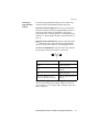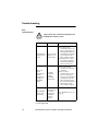
1
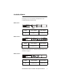
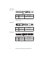
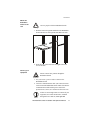
APC
Redundant Switch
Installation and
Operation Manual
®
This manual is available in English on the enclosed CD.
Uživatelská příručka v češtině je k dispozici na přiloženém CD.
Dieses Handbuch ist in Deutsch auf der beiliegenden
CD-ROM verfügbar.
Este manual está disponible en español en el CD-ROM
adjunto.
Ce manuel est disponible en français sur le CD-ROM
ci-inclus.
Questo manuale è disponibile in italiano nel CD-ROM
allegato.
A hasznalati utasitas magyarul megtalalhato a csatolt CD-n.
Denne manualen er tilgjengelig på norsk på vedlagte CD.
Instrukcja Obslugi w języku polskim jest dostępna na CD.
O manual em Português está disponível no CD-ROM em
anexo.
ИНСТРУКЦИЯ ПО ИСПОЛЬЗОВАНИЮ НА РУССКОМ ЯЗЫКЕ
ПРИЛАГАЕТСЯ НА ДИСКЕ (CD).
Denna manual finns tillgänglig på svenska på medföljande CD.
Contents
Before You Begin . . . . . . . . . . . . . . . . . . . . . . . . . 1
Pre-Installation Procedures . . . . . . . . . . . . . . . . . . 2
Available Models. . . . . . . . . . . . . . . . . . . . . . . . . . 3
Installation . . . . . . . . . . . . . . . . . . . . . . . . . . . . . . 6
Configuration . . . . . . . . . . . . . . . . . . . . . . . . . . . 13
Operation . . . . . . . . . . . . . . . . . . . . . . . . . . . . . . 15
Troubleshooting . . . . . . . . . . . . . . . . . . . . . . . . . 18
Specifications . . . . . . . . . . . . . . . . . . . . . . . . . . . 20
Appendix A: Rack-Mount Supplement . . . . . . . . . 23
Warranty and Service . . . . . . . . . . . . . . . . . . . . . 25
Life-Support Policy . . . . . . . . . . . . . . . . . . . . . . . 27
APC Redundant Switch: Installation and Operation Manual
ii
APC Redundant Switch: Installation and Operation Manual
Before You Begin
Safety and
grounding
information
Electrical
Hazard
Read the following information before installing or operating
your APC Redundant Switch.
• Do not work alone under hazardous conditions.
• Check that the power cord, plugs, and sockets are in
good condition.
• To reduce the risk of electric shock when you can not
verify grounding, disconnect the Redundant Switch from
the power outlet before installing or connecting to other
equipment. Reconnect the power cord only after all
connections are made.
• Do not handle any kind of metallic connector before the
power has been removed.
• Use one hand, whenever possible, to connect or
disconnect signal cables to avoid a possible shock from
touching two surfaces with different electrical grounds.
• Connect the equipment to a three-wire AC outlet (two
poles plus ground) that is connected to appropriate
branch circuit/mains protection (a fuse or circuit
breaker). Connection to any other type of receptacle may
result in a shock hazard.
• To turn off and disengage the Redundant Switch, press
and hold both UPS Off buttons for more than one second
to switch the equipment off, then disconnect the
Redundant Switch from the AC power outlet.
• Pluggable equipment includes a protective earth
conductor which carries the leakage current from the
load devices (computer equipment). Total leakage
current must not exceed 3.5 mA.
APC Redundant Switch: Installation and Operation Manual
1
Pre-Installation Procedures
Receiving
inspection
Inspect the package and contents for shipping damage, and
make sure that all parts were sent. Report any damage
immediately to the shipping agent, and report missing contents,
damage, or other problems immediately to APC or your APC
reseller.
Please recycle
The shipping materials are recyclable. Please
save them for later use, or dispose of them
appropriately.
Package
contents
The package contains the following
• The Redundant Switch
• The Redundant Switch hardware kit (OM-8500):
Part Number
Description
Quantity
870-7190
Left Mounting Bracket
1
870-7191
Right Mounting Bracket
1
820-0022
Twist Locks
2
808-0004
Pan-head Phillips Screws
with washers
4
• The 1U mounting rails
• The 1U mounting rails hardware Kit (OM-7600)
Part Number
Description
Quantity
810-0002
Ornamental Screw 10-32
4
810-2004
Snap-on Speed Nut 10-32
4
810-2008
Cage Nut 10-32
4
Select the
installation site
Choose a temperature-controlled area (0° – 50° C, 32° –
122° F), free of conductive contaminants.
2
APC Redundant Switch: Installation and Operation Manual
Available Models
Following is a rear view and basic information for each
available Redundant Switch model.
Model SU041
CA UTION:
®
LISTE D 42C 2
E95463
LR 6393 8
UNINT ERRU PTIBLE
RISK
OFELECTRIC SHOCK. DO NOT REMOVE TOP COVER. NO USER
POW ER SUPPLY SERVICEABLE PARTSI NSI DE. REFERSERVICINGTO QUALIFIEDSERVICE PERSONNEL.
ACCESSO RY
FOR USE IN A CONTROLLED ENVIRONMENT. REFER TO MANUAL FOR ENVIRONMENTAL CONDIT IONS.
MADE IN USA
THIS EQUIPMENT USEST WO(2)ACSOURCES
MOD EL :
S/N:
THIS DEVICE COMPLIESWITHPART 15OF THEFCCRULES.
OPERATION ISSUBJECT TO THEFOLLOWING TWOCONDITIONS
:
1.THISDEVICE MAY NOT CAUSE HARMFUL INTERFERENCE AND
2.THISDEVICE MUST ACCEPT ANY INTERFERENCE RECEI VED
THATMAY CAUSE UNDESIRED OPERATION.
Voltage
Source (Input)
Load (Output)
1400 VA
120 V
2 NEMA 5-15
2 NEMA 15-5
Voltage
Source (Input)
Load (Output)
3000 VA
120 V
2 NEMA L5-30
2 NEMA 5-20
Model SU042-1
CA UTION:
®
LISTE D 42C 2
E95463
LR 6393 8
UNINT ERRU PTIBLE
RISK OF ELECTRIC SHOCK. D
O NOT REMOVE TOP COVER. NO USER
POW ER SUPPLY SERVICEABLE PARTSINSI DE. REFERSERVICINGTO QUALIFIEDSERVICE PERSONNEL.
ACCESSO RY
FORUSE IN ACONTROLLEDENVIRONMENT. REFERTOMANUAL FOR ENVIRONMENTALCONDITIONS .
MADE IN USA
THIS EQUIPMENT USESTWO(2)ACSOURCES
MOD EL :
S/N:
THIS DEVICE COMPLIESWITHPART 15OF THE FCCRULES.
OPERATION ISSUBJECT TO THEFOLLOW ING TWOCONDITIONS
:
1.THISDEVICE MAY NOT CAUSE HARMFUL INTERFERENCE AND
2.THISDEVICE MUST ACCEPT ANY INTERFERENCE RECEI VED
THAT MAY CAUSE UNDESIRED OPERATION.
For information on the circuit breaker safety device and load
indicator for this model, see “Features of models SU042-1 and
SU042-4” on page 5.
Model SU042-2
CAU TION:
®
LISTE D 42C 2
E95463
LR 63938
UNINT ERRUPT IBLE
RISK OF ELECTRICSHOC
K
POW ER SU PPLY SERVICEABLE PARTSINSIDE. REFERSERVICINGTO QUALIFIED SERVICE PERSONNEL.
ACCESSORY
FORUSE INACONTROLLEDENVIRONMENT. REFERTOMANUAL FOR ENV IRONMENTALCONDITIONS .
MADE IN USA
THIS EQUIPMENT USESTWO(2) ACSOURCES
THIS DEVICE COMPLIESWITH PART 15OF THEFCCRULES.
OPERATION ISSUBJECT TOTHEFOLLO WING TWOCONDITION
. DO NOT REMOVE TOP COVER. NO USER
MOD EL :
S/N :
S:
1.THISDEVI CE MAY NOT CAUSE HARMFUL INTERFERENCE AND
2.THISDEVI CE MUST ACCEPT ANY INTERFERENCE RECEIVED
THAT MAY CAUSEUNDESIREDOPERATION.
Voltage
Source (Input)
3000 VA
120 V
2 NEMA L5-30
Load (Output)
1 NEMA L5-30
(captive cord)
APC Redundant Switch: Installation and Operation Manual
3
Available Models
Model SU042-4
Voltage
Source (Input)
3000 VA
120 V
2 NEMA L5-30
Load (Output)
6 NEMA 5-20 (limited to 15 A
from the circuit breaker)
For information on the circuit breaker safety device and load
indicator for this model, see “Features of models SU042-1 and
SU042-4” on page 5.
Model SU043
IN PU T V O LTA G E: 2 2 0- 24 0 VA C
MO D EL
1 40 0
3 00 0
Ge pr ü ft e
S ic he rh ei t
MO DEL :
S/N:
MA X I
8A
1 6A
Voltage
Source (Input)
Load (Output)
1400 VA
230 V
2 IEC 320 C14
2 IEC 320 C13
Model SU044-1
SEE OWNER'S MANUAL
IN PU T V O LTA G E: 2 x AC 2 2 0- 24 0V ; 5 0-6 0 Hz
Ge pr ü ft e
S ic he rh ei t
M O D EL
I NP U T
S U 043
2 x 8 A (1 4 0 0 VA )
MO DEL :
S/N:
O U T PU T
2 x AC 2 2 0 -2 4 0 V; 2 x 8 A
S U 0 4 4 - 1 2 x 1 6 A ( 3 0 0 0 V A ) 2 x A C 2 2 0 - 2 4 0 V ; 1 x 1 6 A ,2 x 8 A
S U 0 4 4 -2 2 x 1 6 A (3 0 0 0 VA ) 2 x AC 2 2 0 -2 4 0 V; 2 x 1 6 A
4
Voltage
Source (Input)
Load (Output)
3000 VA
230 V
2 IEC 320 C20
1 IEC 320 C19
2 IEC 320 C13
APC Redundant Switch: Installation and Operation Manual
Available Models
Model SU045-1
CAU TION:
UNINT ERRUPT IBLE
RIS KOF ELECTRIC SHOCK.
POW ER SU PPLY SERVICEABLE PARTSINSIDE. REFER SERVICINGTOQUALIFIEDSERVICE PERSONNEL .
ACCESSOR Y
FORUSE IN ACONTROLLEDENVIRONMENT. REFERTO MANUAL FOR ENVIRONMENTAL
®
LISTE D 42C 2
E95463
LR 63938
MADE IN USA
THIS EQUIPMENT USESTWO(2) AC SOURCES
THIS DEVICE COMPLI ES WI THPART 15OFTHE FCCRULES.
OPERATION ISSUBJECT TOTHEFOLLOWINGTWOCONDITION
DO NOT REMOVE TOP COVER. NO USER
CONDIT IONS .
MOD EL :
S/N :
S:
1.THISDEVICE MAY NOT CAUSE HARMFUL INTERFERENCEAND
2.THISDEVICE MUST ACCEPT ANY INTERFERENCE RECEI VED
THAT MAY CAUSE UNDESIREDOPERATION.
Features of
models SU042-1
and SU042-4
Voltage
Source (Input)
3000 VA
208 V
2 NEMA L6-20
Load (Output)
1 NEMA L6-20
(captive cord)
Safety device. Models SU042-1 and SU042-4 have a red circuit
breaker safety device attached to each circuit breaker switch.
Do not remove this device.
• The device prevents accidentally tripping of the circuit
breaker, but allows the automatic tripping of the breaker
that protects your equipment when an overload or
malfunction occurs.
• To turn the circuit breaker off when necessary, pull the
left end of the safety device forward so that it no longer
blocks the switch, then push the switch to the OFF
position.
• To reset a circuit breaker that has tripped automatically:
– Pull the left end of the safety device forward so that it
no longer blocks the switch.
– Let the switch move fully to the left, then push it to the
right.
– Push the left end of the safety device back into place to
block the switch.
Outlet Control indicator. The number to the left of each
circuit breaker switch indicates which set of outlets it controls:
LOAD 1 or LOAD 2.
APC Redundant Switch: Installation and Operation Manual
5
Installation
Install
management
products and
the UPS
1. Before you plug in the Redundant Switch and the two
UPSs, install any compatible APC management products:
– If you use a Web/SNMP Management Card, install it
in the card slot of the preferred APC Smart-UPS, not in
the card slot of the Redundant Switch.
– Always use the card slot in the Redundant Switch for
any other compatible APC management product, such
as the Environmental Monitoring Card.
The Redundant Switch inlets are the main
disconnect devices.
Note
For multiple APC accessory configurations, visit
the APC Web site (www.apcc.com)
2. To install each UPS, follow the installation instructions
in the UPS User’s Manual.
– Make sure both UPSs are the same sine-wave model.
– Plug the power cords attached to the Redundant
Switch into each UPS.
6
APC Redundant Switch: Installation and Operation Manual
Installation
Attach the
brackets to the
Redundant
Switch
Attach the two included brackets to the Redundant Switch. The
following example shows how to attach the bracket for the
right side. (Attach the left bracket in the same manner.)
1. To allow space to route the cables and to place the
connectors flush with the front of the rack, align the
second hole from the front of the bracket with the first
hole in the side of the Redundant Switch.
2. Insert and tighten the screws that are provided.
APC Redundant Switch: Installation and Operation Manual
7
Installation
Install the rails
(4-post rack
only)
Mount the rails only if you are using a four-post rack. (In a
two-post rack, you mount the Redundant Switch by the
brackets alone.)
For information on which clips and screws your rack requires,
see Appendix A: Rack-Mount Supplement.
"
#
For a four-post rack:
1. Prepare the rack’s rail-holes for mounting the brackets
and rails of the Redundant Switch.
2. Disassemble each rail by removing the slide screw and
nut !. Set aside the screw, nut, and front segment " of
the rail.
3. Mount the end # of the rear segment of each rail to the
rear rails on the prepared rack, using appropriate rack
hardware.
8
APC Redundant Switch: Installation and Operation Manual
Installation
4. On each side, attach the front rail segment that you set
aside in step 2 to the Redundant Switch.
a. Align the top two holes on the front rail segment with
the two holes on the side (toward the rear) of the
Redundant Switch.
b. Attach the rail segment with the tapered-head screws
provided.
APC Redundant Switch: Installation and Operation Manual
9
Installation
Connect and
route the cables
1. To the front of the Redundant Switch, connect the
communications cable and any accessory cables that
require front connections.
2. Route the cables around the Redundant Switch through
the side channel (marked with arrows below) to the
equipment in the rack.
Redundant Switch
3. Optionally, install a plastic twist-lock (provided) on each
side to secure the cables.
10
APC Redundant Switch: Installation and Operation Manual
Installation
Mount the
Redundant
Switch in the
rack
Use two people to lift the Redundant Switch.
Heavy
1. Slide the front rail segments attached to the Redundant
Switch into the rear rail segments attached to the rack.
2. From the rear of the rack, insert and tighten the slide
screws and nuts.
Connect your
equipment
Do not connect laser printers through the
Redundant Switch
Caution
1. Use your server’s power cords to connect to the
Redundant Switch.
2. Connect a communications cable (940-1000A) between
each UPS and the Redundant Switch. Make sure that the
communications cable and the power cord for the
preferred UPS (UPS-A) are connected to the same UPS.
Note
If there are not enough outlets to connect all your
equipment, use a Rack-mount PDU, available
through the APC Web site, www.apc.com.
APC Redundant Switch: Installation and Operation Manual
11
Installation
Turn on the
equipment and
Redundant
Switch
Connect the
PowerChute®
cable
1. Turn on all connected equipment.
2. To provide power to the equipment, press the ON button
of UPS-A to turn on the Redundant Switch and UPS-B.
3. To test whether the cables are connected correctly, press
the OFF button on one UPS.
– If it turns back on, the cabling is correct.
– If it does not turn back on, try swapping the two UPS
communications cables to correct the problem.
When you are ready to install PowerChute plus, install the
PowerChute plus communications cable between the server
port of the Redundant Switch and your server’s serial port.
Note
12
To use PowerChute plus software to manage a
Redundant Switch configuration, your server
must be running Windows NT, Solaris, or
NetWare. See your PowerChute plus
documentation for the operating system versions
that are supported.
APC Redundant Switch: Installation and Operation Manual
Configuration
Supported
configurations
Two supported configurations for Redundant Switch are shown
below. For more information on these and other supported
configurations, visit the APC Web site at www.apc.com.
Install only SNMP accessories in the UPS. You
must install any other accessories in the
Redundant Switch
Note
Both UPSs must be the same sine-wave model.
Minimum acceptable
configuration: Redundant Switch
with two Smart-UPS units
connected to one AC line (the same
facility power source).
Best configuration: Redundant
Switch with two Smart-UPS units
connected to two separate AC lines
(each UPS receiving power from a
separate facility power source).
Configuring
PowerChute
1. Install PowerChute plus as described in the enclosed
software installation instructions.
plus
2. For Source B:
a. At the Redundant Switch front panel, set the Source
Preference to Source B.
b. Start the computer on which PowerChute plus is
installed.
c. Start PowerChute plus. Communication is to UPS-B.
d. Configure UPS-B according to your requirements.
e. Set the UPSID to UPS_B.
3. For Source A:
a. At the Redundant Switch front panel, set the Source
Preference to Source A.
APC Redundant Switch: Installation and Operation Manual
13
Configuration
b. Restart the computer on which PowerChute plus is
installed.
c. Start PowerChute plus. Communication is to UPS-A.
d. Configure UPS-A according to your requirements.
e. Set the UPSID to UPS_A.
When one UPS
becomes
unavailable
When one of the two UPSs becomes unavailable to supply AC
power, PowerChute plus sends the message “Self test failed:
invalid test.” Any of the following conditions will cause the
message to occur:
• A UPS self-test fails.
• Communication with the alternate UPS is lost.
• The voltage of the alternate UPS is out of range.
• UPS-A fails, and the Redundant Switch transfers the
power input and PowerChute plus communication to
UPS-B.
To regain high availability for your system, correct the problem
as soon as possible. See “Troubleshooting” on pa ge18.
Note
14
When any self-test of the primary UPS occurs,
the Redundant Switch switches power and
communication to the other UPS, causes a selftest of that UPS, and then switches back. This is
normal behavior.
APC Redundant Switch: Installation and Operation Manual
Operation
Controls, LEDs,
and ports on the
front panel
Redundant Switch
Storage
APC recommends the factory default settings
among the settings shown below.
Note
Function
Source A
Sensitivity
Source B
Sensitivity
Source
Preference
LED Display
Description
Bright= Normal
Dim (the factory
default) = Reduced
Sets transfer
sensitivity to line
conditions
Off = low
Bright = Source A
(the factory default)
Dim = Source B
Selects the preferred
AC source
Off = none
Source A
Xfer
Voltage
Bright = Narrow
Source B
Xfer
Voltage
Off = Wide
Dim = Medium (the
factory default
Sets the transfer
voltage window (the
range of acceptable
voltage)
APC Redundant Switch: Installation and Operation Manual
15
Operation
Emergency
Power Off
You can use a remotely operated Emergency Power Off (EPO)
switch to turn off the UPS and disconnect power to the
equipment load. When you turn off the UPS through the
Emergency Power Off system, it will turn off immediately
without switching to battery operation.
Electrical
Hazard
Use only a licensed electrician to perform the
following procedure to connect the Redundant
Switch and its attached UPSs to your
Emergency Power Off system.
1. Use the EPO connector.
2. Use a normally-open contact to connect the +24 terminal
to the IN terminal.
3. Wire the external blue four-pin female connector to the
emergency power off system.
The EPO interface is a Safety Extra Low Voltage
(SELV) circuit. Connect it only to other SELV
circuits.
Caution
16
The EPO interface monitors circuits that have no
determined voltage potential. Such closure
circuits may be provided by a switch or relay
properly isolated from the utility. To avoid
damage to the Redundant Switch, do not connect
the EPO interface to any circuit other than a
closure type circuit.
APC Redundant Switch: Installation and Operation Manual
Operation
Front panel
programmable
settings
The following programmable settings are accessible using
controls located on the Redundant Switch front panel.
Function Select LED Indicator. The three green Function
Select LEDs indicate which user programmable parameter is
selected for status display or modification. Use the left
selection button to cycle through the five configurable items
defined in “Controls, LEDs, and ports on the front panel” on
page 15.
Function Status LED Indicator. The green Function Status
LED indicates the state of the selected user programmable
function. Use the Select button to cycle among the choices.
AC Source LED Indicator. The green online LED indicates
the line quality and selection status of each source:
LED Display
Status of Source
Bright
Source is selected.
Dim
Source is OK, but not
selected.
Off
Source is not OK.
One LED is flashing once per
second, and the other LED is off
Both AC sources are out of
tolerance.
Source Sensitivity and Transfer Voltage. APC recommends
that you do not change these settings, which are correct for
most conditions. See “Controls, LEDs, and ports on the front
panel” on page 15.
APC Redundant Switch: Installation and Operation Manual
17
Troubleshooting
Basic
troubleshooting
Electrical
Hazard
Only trained APC technicians should open the
Redundant Switch for repair.
Problem
Possible Cause
Corrective Actions
Very low utility
voltage, or no
utility voltage.
Use a lamp with an
incandescent bulb to test
the AC power supply to
the Redundant Switch. If
the bulb lights very dimly
or not at all, have the
utility voltage checked.
Ensure that the AC cables
are properly connected
between the Redundant
Switch and the UPSs.
The server
cannot
communicate
with the
attached UPS
through the
Redundant
Switch
A cabling
problem or
internal
Redundant
Switch fault
Ensure that all cables
connections are securely
connected.
If there is still no
communication, connect
the server directly to a
UPS. If you can establish
communication by this
direct connection, there
is an internal Redundant
Switch fault. Contact
APC Customer Support.
All Redundant
Switch LEDs
are flashing
An Internal,
automated selftest failure
occurred; the
Redundant
Switch is
defective.
See “Obtaining service” on
page 25.
The Redundant
Switch will not
turn on.
For computer interface port specifications, see the APC Web
site, www.apc.com.
18
APC Redundant Switch: Installation and Operation Manual
Troubleshooting
Troubleshooting
communications
and lost
redundancy
With the high availability system, the attached UPSs are polled
continuously for capability to carry a load and ability to
communicate with the management software (PowerChute
plus). When a problem with one of the UPSs occurs, power to
the load is not interrupted and polling continues, and
PowerChute plus responds by displaying the message, “Self
test failed: invalid test.”
Communications Problems. If the message “Self test failed:
invalid test.” occurs repeatedly:
1. Check the communications path between the UPSs and
the Redundant Switch.
2. Check the front panel of the Redundant Switch.
– If the Status Select LEDs are flashing in any sequence,
the Redundant Switch has failed. See “Basic
troubleshooting” on page 18.
– If the front panel appears normal, there may be a UPS
or server communications problem, See the
troubleshooting and service sections of your UPS
manuals.
– If you need more help, contact APC Worldwide
Customer Support.
Loss of Redundancy. If the Redundant Switch LED for UPS-B
is off, UPS-B has lost the ability to provide power to the
equipment load when engaged. If the LED for UPS-A is off,
UPS-A has failed, and power is now provided by UPS-B. See
the troubleshooting and service sections of your UPS manuals.
If PowerChute plus displays the message “self test failed:
invalid test” briefly or several times, the output voltage of
UPS-A has dropped. Perform a UPS self-test through
PowerChute plus.
• If the self test fails, see the troubleshooting and service
sections of your UPS manuals.
• If you need more help, contact APC Worldwide
Customer Support.
APC Redundant Switch: Installation and Operation Manual
19
Specifications
SU041,
SU042-1,
SU042-2, and
SU042-4
Item
Specification
Power
Nominal input voltage
120VAC
Input voltage range
0 – 165 VAC
Frequency range
47 – 63 Hz
Normal sensitivity transfer times
8 ms maximum at 60 Hz
10 ms maximum at 50 Hz
Reduced sensitivity transfer
times
16 ms maximum at 60 Hz
20 ms maximum at 50 Hz
Maximum current draw
12A (SU041 model)
24A (SU042 models)
Physical
Size:
1.75 × 17.0 × 7.5 in
4.45 × 43.2 × 19 cm
Net weight
10 lb (4.5 kg)
Shipping weight
15 lb (6.8 kg)
Environmental
Elevation (above MSL):
• Operating
• Storage
0 to 10,000 ft (0 to 3000 m)
0 to 50,000 ft (0 to 1500 m)
Temperature:
• Operating
• Storage
32° to 122° F (0 to 50° C)
5° to 122° F (– 15° to 50° C)
Relative Humidity
(Operating and Storage)
0 to 95%, non-condensing
Approvals/Standards
UL, CSA, FCC Class A
20
APC Redundant Switch: Installation and Operation Manual
Specifications
SU043 and
SU044-1
Item
Specification
Power
Nominal input voltage
230VAC
Input voltage range
0 – 325 VAC
Frequency range
47 – 63 Hz
Normal sensitivity
transfer times
4 ms typical, 8 ms maximum at 60 Hz
5 ms typical, 10 ms maximum at 50 Hz
Reduced sensitivity
transfer times
8 ms typical, 16 ms maximum at 60 Hz
10 ms typical, 20 ms maximum at 50 Hz
Maximum current
draw
6 A (SU043 model)
13A (SU044-1 model)
Physical
Size:
1.75 × 17.0 × 7.5 in
4.45 × 43.2 × 19 cm
Net weight
10 lb (4.5 kg)
Shipping weight
15 lb (6.8 kg)
Environmental
Elevation (above
MSL):
• Operating
• Storage
Temperature:
• Operating
• Storage
Relative Humidity
(Operating and
Storage)
0 to 10,000 ft (0 to 3000 m)
0 to 50,000 ft (0 to 1500 m)
32° to 122° F (0 to 50° C)
5° to 122° F (– 15° to 50° C)
0 to 95%, non-condensing
Approvals/Standards
CE, VDE, EN55022, EN55024
APC Redundant Switch: Installation and Operation Manual
21
Specifications
SU045
Item
Specification
Power
Nominal input voltage
208VAC
Input voltage range
0 – 275 VAC
Frequency range
47 – 63 Hz
Normal sensitivity
transfer times
4 ms typical, 8 ms maximum at 60 Hz
5 ms typical, 10 ms maximum at 50 Hz
Reduced sensitivity
transfer times
8 ms typical, 16 ms maximum at 60 Hz
10 ms typical, 20 ms maximum at 50 Hz
Maximum current
draw
14A
Physical
Size:
1.75 × 17.0 × 7.5 in
4.45 × 43.2 × 19 cm
Net weight
10 lb (4.5 kg)
Shipping weight
15 lb (6.8 kg)
Environmental
Elevation (above
MSL):
• Operating
• Storage
Temperature:
• Operating
• Storage
Relative Humidity
(Operating and
Storage)
0 to 10,000 ft (0 to 3000 m)
0 to 50,000 ft (0 to 1500 m)
32° to 122° F (0 to 50° C)
5° to 122° F (– 15° to 50° C)
0 to 95%, non-condensing
Approvals/Standards
UL, CSA, FCC Class A
22
APC Redundant Switch: Installation and Operation Manual
Appendix A: Rack-Mount Supplement
Installation for
rack-mount
units
The Redundant Switch is provided with brackets for mounting
in standard 19 in.(46.5 cm.) rack.
Select a rack location with adequate air flow that is free from
excessive dust. Do not operate the Redundant Switch where
temperature or humidity are outside the limits listed under
“Specifications,” beginning on page 20.
APC Redundant Switch: Installation and Operation Manual
23
Appendix A: Rack-Mount Supplement
Rail hardware
Different types of racks require different rail hardware.
Type of Rack
Hole Type
Hardware Required
Threaded
or not
threaded
For threaded holes, see rack
specifications. Threaded
holes do not require nuts.
For non-threaded holes, use
APC hardware provided.
Square
Cage nuts: 10-32 internal
thread, APC part number
810-2008. (See below.)
Screws: 10-32 thread,
Phillips head, APC part
number 810-0002.
Hewlett Packard:
enclosure
Round
Clip nuts: 10-32 internal
thread, APC part number
810-2004. (See below.)
Screws: 10-32 thread,
Phillips head. APC part
number 810-0002.
Telecommunications open rack
with 2 or 4 poles
Threaded
See rack specification. No
hardware provided by APC.
Equipment Rack:
usually an open
rack
APC NetShelter®,
Compaq®, IBM®,
Dell®, Vero®,
Rittal®: enclosures
The following APC clip nuts and cage nuts, mentioned in the
preceding table, are provided with the Redundant Switch:
• Clip Nut (810-2004)
• Cage Nut (810-2008)
24
APC Redundant Switch: Installation and Operation Manual
Warranty and Service
Limited
warranty
APC warrants the Redundant Switch to be free from defects in
Warranty
limitations
Except as provided herein, APC makes no warranties,
express or implied, including warranties of merchantability
and fitness for a particular purpose. Some jurisdictions do
not permit limitation or exclusion of implied warranties;
therefore, the aforesaid limitation(s) or exclusion(s) may not
apply to the purchaser.
materials and workmanship for a period of two years from the
date of purchase. Its obligation under this warranty is limited to
repairing or replacing, at its own sole option, any such
defective products. This warranty does not apply to equipment
that has been damaged by accident, negligence, or
misapplication or has been altered or modified in any way. This
warranty applies only to the original purchaser.
Except as provided above, in no event will APC be liable for
direct, indirect, special, incidental, or consequential
damages arising out of the use of this product, even if
advised of the possibility of such damage.
Specifically, APC is not liable for any costs, such as lost profits
or revenue, loss of equipment, loss of use of equipment, loss of
software, loss of data, costs of substitutes, claims by third
parties, or otherwise. This warranty gives you specific legal
rights and you may also have other rights, which vary
according to jurisdiction.
Obtaining
service
To obtain support for problems with your Redundant Switch:
0
1. Note the serial number and date of purchase. The serial
number is located on the back of the Redundant Switch.
2. Contact Customer Support at a phone number on the
back cover of this document. A technician will try to
help you solve the problem by phone.
3. If you must return the product, the technician will give
you a return material authorization (RMA) number. If the
warranty expired, you will be charged for repair or
APC Redundant Switch: Installation and Operation Manual
25
Warranty and Service
replacement.
4. Pack the unit carefully. The warranty does not cover
damage sustained in transit. Enclose a letter with your
name, address, RMA number and daytime phone
number; a copy of the sales receipt; and a check as
payment, if applicable.
5. Mark the RMA number clearly on the outside of the
shipping carton.
6. Ship by insured, prepaid carrier to the address provided
by the Customer Support technician.
26
APC Redundant Switch: Installation and Operation Manual
Life-Support Policy
General policy
American Power Conversion (APC) does not recommend the
use of any of its products in the following situations:
• In life-support applications where failure or malfunction
of the APC product can be reasonably expected to cause
failure of the life-support device or to affect significantly
its safety or effectiveness.
• In direct patient care.
APC will not knowingly sell its products for use in such
applications unless it receives in writing assurances
satisfactory to APC that (a) the risks of injury or damage have
been minimized, (b) the customer assumes all such risks, and
(c) the liability of American Power Conversion is adequately
protected under the circumstances.
a
Examples of
life-support
devices
The term life-support device includes but is not limited to
neonatal oxygen analyzers, nerve stimulators (whether used for
anesthesia, pain relief, or other purposes), autotransfusion
devices, blood pumps, defibrillators, arrhythmia detectors and
alarms, pacemakers, hemodialysis systems, peritoneal dialysis
systems, neonatal ventilator incubators, ventilators (for adults
and infants), anesthesia ventilators, infusion pumps, and any
other devices designated as “critical” by the U.S. FDA.
Hospital-grade wiring devices and leakage current protection
may be ordered as options on many APC UPS systems. APC
does not claim that units with this modifications are certified or
listed as hospital-grade by APC or any other organization.
Therefore these units do not meet the requirements for use in
direct patient care.
A
APC Redundant Switch: Installation and Operation Manual
27
Radio Frequency Interference
Warning
Changes or modifications to this unit not
expressly approved by the party responsible
for compliance could void the user’s authority
to operate this equipment.
This equipment has been tested and found to comply with the
limits for a Class A digital device, pursuant to part 15 of the
FCC Rules. These limits are designed to provide reasonable
protection against harmful interference when the equipment is
operated in a commercial environment. This equipment
generates, uses, and can radiate radio frequency energy and, if
not installed and used in accordance with this user manual,
may cause harmful interference to radio communications.
Operation of this equipment in a residential area is likely to
cause harmful interference. The user will bear sole
responsibility for correcting such interference.
This Class A digital apparatus complies with Canadian
ICES-003.
Cet appareil numérique de la classe A est conforme à la norme
NMB-003 du Canada.
a
®
APC Worldwide Customer Support
Customer support for this or any other APC product is available at no charge in any of the
following ways:
•
Visit the APC Web site to find answers to frequently asked questions (FAQs), to
access documents in the APC Knowledge Base, and to submit customer support
requests.
– www.apc.com (Corporate Headquarters)
Connect to localized APC Web sites for specific countries, each of which
provides customer support information.
– www.apc.com/support/
Global support with FAQs, knowledge base, and e-support.
•
Contact an APC Customer Support center by telephone or e-mail.
– Regional centers:
APC headquarters U.S.,
Canada
–
(1)(800)800-4272 (toll free)
Latin America
(1)(401)789-5735 (USA)
Europe, Middle East, Africa
(353)(91)702020 (Ireland)
Japan
(03)5434-2021 Guidance 3
Local, country-specific centers: go to www.apc.com/support/contact for
contact information.
Contact the APC representative or other distributor from whom you purchased your APC
product for information on how to obtain local customer support.
Entire contents copyright © 2002 American Power Conversion. All rights
reserved. Reproduction in whole or in part without permission is prohibited.
APC, the APC logo, and PowerChute are trademarks of American Power
Conversion Corporation and may be registered in some jurisdictions. All other
trademarks, product names, and corporate names are the property of their
respective owners and are used for informational purposes only.
990-0253B
03/2002