1
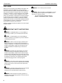
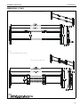
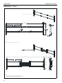
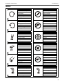
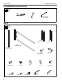
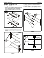
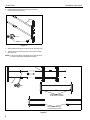
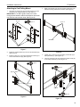
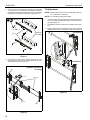
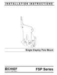
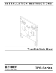
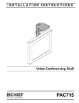
INSTALLATION INSTRUCTIONS
‘
To Cart/ceiling Mount
To Wall Mount
Fusion™ Side Channel Speaker Adapters
Spanish Product Description
German Product Description
Portuguese Product Description
Italian Product Description
Dutch Product Description
French Product Description
FCA831/841
FCA831/841
Installation Instructions
DISCLAIMER
Milestone AV Technologies and its affiliated corporations and
subsidiaries (collectively “Milestone”), intend to make this
manual accurate and complete. However, Milestone makes no
claim that the information contained herein covers all details,
conditions or variations, nor does it provide for every possible
contingency in connection with the installation or use of this
product. The information contained in this document is subject
to change without notice or obligation of any kind. Milestone
makes no representation of warranty, expressed or implied,
regarding the information contained herein. Milestone assumes
no responsibility for accuracy, completeness or sufficiency of
the information contained in this document.
Chief® is a registered trademark of Milestone AV Technologies.
All rights reserved.
IMPORTANT SAFETY INSTRUCTIONS
WARNING: A WARNING alerts you to the possibility of
serious injury or death if you do not follow the instructions.
CAUTION: A CAUTION alerts you to the possibility of
damage or destruction of equipment if you do not follow the
corresponding instructions.
WARNING: Failure to read, thoroughly understand, and
follow all instructions can result in serious personal injury,
damage to equipment, or voiding of factory warranty! It is the
installer’s responsibility to make sure all components are
properly assembled and installed using the instructions
provided.
WARNING: Exceeding the weight capacity can result in
serious personal injury or damage to equipment! It is the
installer’s responsibility to make sure the combined weight
mounted to the FCA831/841 does not exceed 10 lbs (4.5 kg)
per side or 20 lbs (9 kg) total if installing to cart/ceiling mount.
If installing to a wall mount, the combined weight cannot
exceed 20 lbs (9 kg) per side or 40 lbs (18 kg) total.
WARNING: Use of this accessory will decrease the weight
capacity of the mount to which it is attached by the combined
weight of the accessory and all components supported by
this accessory!
WARNING: Use this mounting system only for its intended
use as described in these instructions. Do not use
attachments not recommended by the manufacturer.
WARNING: Never operate this mounting system if it is
damaged. Return the mounting system to a service center for
examination and repair.
2
WARNING: Do not use this product outdoors.
WARNING: RISK OF INJURY TO PERSONS! Do not use
this mounting system to support video equipment such as
televisions or computer monitors.
--SAVE THESE INSTRUCTIONS--
Installation Instructions
FCA831/841
DIMENSIONS - FCA831
FUSION WALL MOUNT SETUP
.9
22.2
34.4-57.8
(MEDIUM LANDSCAPE MOUNTS)
15.8
400.1
(*)NOTES:
•
TYPICAL FUSION INTERFACES ARE 0.625" [15.9] DEEP
CEILING/CART MOUNT SET-UP
.9
22.2
36.2-57.6
(MEDIUM LANDSCAPE MOUNTS)
15.8
400.1
3
FCA831/841
Installation Instructions
DIMENSIONS - FCA841
FUSION WALL MOUNT SETUP
44.8-84.8
[1137.9-2153.9]
.9
22.2
.7 *
17.3
22.2
563.8
15.8
400.1
7.0
177.8
.25-1.1
[6.35-14.30]
1.8
45.6
(*)NOTES:
•
TYPICAL FUSION INTERFACES ARE 0.625" [15.9] DEEP
46.2-77.6
[1173.5-1971.0]
.9
22.2
10°
22.3
565.7
.4 *
11.1
7.0
177.8
15.8
400.1
2.6
66.4
(*)NOTES:
•
•
•
4
10°
TYPICAL SINGLE DISPLAY MODELS HAVE INTERFACE DEPTHS .5" [12.7]
TYPICAL DUAL DISPLAY MODELS HAVE INTERFACE DEPTHS 1.9" [48.3]
FCA623 DUA L M ONITOR INTERFACES ARE 1.4" DEEP [35.6]
Installation Instructions
FCA831/841
LEGEND
Tighten Fastener
Pencil Mark
Apretar elemento de fijación
Marcar con lápiz
Befestigungsteil festziehen
Stiftmarkierung
Apertar fixador
Marcar com lápis
Serrare il fissaggio
Segno a matita
Bevestiging vastdraaien
Potloodmerkteken
Serrez les fixations
Marquage au crayon
Loosen Fastener
Drill Hole
Aflojar elemento de fijación
Perforar
Befestigungsteil lösen
Bohrloch
Desapertar fixador
Fazer furo
Allentare il fissaggio
Praticare un foro
Bevestiging losdraaien
Gat boren
Desserrez les fixations
Percez un trou
Phillips Screwdriver
Adjust
Destornillador Phillips
Ajustar
Kreuzschlitzschraubendreher
Einstellen
Chave de fendas Phillips
Ajustar
Cacciavite a stella
Regolare
Kruiskopschroevendraaier
Afstellen
Tournevis à pointe cruciforme
Ajuster
Open-Ended Wrench
Remove
Llave de boca
Quitar
Gabelschlüssel
Entfernen
Chave de bocas
Remover
Chiave a punte aperte
Rimuovere
Steeksleutel
Verwijderen
Clé à fourche
Retirez
By Hand
Optional
A mano
Opcional
Von Hand
Optional
Com a mão
Opcional
A mano
Opzionale
Met de hand
Optie
À la main
En option
Hex-Head Wrench
Security Wrench
Llave de cabeza hexagonal
Llave de seguridad
Sechskantschlüssel
Sicherheitsschlüssel
Chave de cabeça sextavada
Chave de segurança
Chiave esagonale
Chiave di sicurezza
Zeskantsleutel
Veiligheidssleutel
Clé à tête hexagonale
Clé de sécurité
5
FCA831/841
Installation Instructions
TOOLS REQUIRED FOR INSTALLATION
#2
3/16” (included)
1/8” (included)
7/16”
PARTS
C (2)
[Clamp bracket]
D (2)
[Clamp cover]
B (2)
[Rail extension]
A (2)
[Speaker bracket]
E (2)
[Thumb screw]
G (4)
[Rail bushing]
M (4)
1/4-20 x 1/2”
6
H (12)
1/4-20”
N (4)
#10-24 x 1/2”
K (8)
#10
J (4)
1/4”
P (4)
5/16-18 x 1/2”
Q (1)
3/16”
F (4)
[T-slot stud]
L (6)
#10-24 x 3/8”
R (1)
1/8”
Installation Instructions
FCA831/841
ASSEMBLY AND INSTALLATION
3.
Install four rail bushings (G) onto two rail extensions (B).
(See Figure 3)
Attaching to Wall Mount
4.
Install four 5/16-18 x 1/2” button head flange screws (P) to
ends of rail extensions (B). (See Figure 3)
1.
Use two 1/4-20 x 1/2” Phillips pan machine screws (M) with
four 1/4” washers (J) or four 10-24 x 1/2” Phillips pan
machine screws (N) with four #10 washers (K) to secure two
speaker brackets (A) to speakers (not included). (See
Figure 1)
(M) or (N) x 4
1
4
(P) x 4
3
(G) x 4
(J) or (K) x 4
speakers
(example)
(A) x 2
(B) x 2
Figure 1
2.
Use six #10-24 x 3/8” button head cap screws (L) to secure
two speaker brackets (A) to two rail extensions (B). (See
Figure 2)
(A)
(speakers not shown
for clarity)
Figure 3
5.
Remove end caps from wall mount rails. (See Figure 4)
Left side
5
Fusion Mount
2
(L) x 6
Right side
(A)
(B) x 2
Figure 4
Figure 2
7
FCA831/841
6.
Installation Instructions
Install and tighten the thumb screw (E) on each rail
extension (B). (See Figure 5)
(B) x 2
6
(E) x 2
Figure 5
7.
Slide rail extensions (B) into wall mount rails. (See Figure 6)
8.
Tighten the four rail bushings (G) into the wall mount rails.
(See Figure 6)
NOTE: It may be necessary to lift slightly on the rail extensions
in order to tighten the side speaker bushings.
FUSION Mount
7
(B)
8
(G)
Side Speaker Bushing
for Minimum Extension
Side Speaker Bushing
for Maximum Extension
Figure 6
8
Installation Instructions
FCA831/841
Attaching to Cart/Ceiling Mount
1.
4.
Slide t-slot studs (F) into grooves on back of extrusion until
desired mounting positions are reached. (See Figure 9)
Use eight 1/4-20 hex nuts (H) to loosely secure four t-slot
studs (F) to two clamp brackets (C). (See Figure 7)
IMPORTANT ! : Do NOT tighten at this time. Leave
enough space between studs and brackets so that studs
can slide into cart extrusion slots. (See Figure 9)
(C) x 2
(H) x 8
1
(F) x 4
4
4
extrusion
(F) x 4
Figure 7
2.
Install two clamp brackets (C) onto two rail extensions (B).
(See Figure 8)
3.
Install four 5/16-18 x 1/2” button head flange screws (P) to
ends of rail extensions (B). (See Figure 8)
Figure 9
5.
Tighten four 1/4-20 hex nuts (H) holding t-slot studs (F) to
clamp brackets (C). (See Figure 10)
6.
Use four 1/4-20 hex nuts (H) to secure two clamp covers (D)
to two clamp brackets (C). (See Figure 10)
(P) x 4
3
(rear view)
5
(B) x 2
(H) x 4
(D) x 2
2
2
(C) x 2
(C) x 2
6
(H) x 4
Figure 8
Figure 10
9
FCA831/841
7.
Installation Instructions
Use four 1/4-20 x 1/2” Phillips pan machine screws (M) with
1/4” washers (J) or four #10-24 x 1/2” Phillips pan machine
screws (N) with four #10 washers (K) to secure two speaker
brackets (A) to speakers (not included). (See Figure 11)
Tilt Adjustment
NOTE: FCA831 and FCA841 mounts are designed to allow for
10° of tilt forward or backward.
NOTE: For cart/ceiling configurations ONLY.
(M) or (N) x 4
7
(J) or (K) x 4
1.
Loosen (do NOT remove) upper and lower button head cap
screws (L) holding speaker brackets (A) to rail extensions
(B). (See Figure 13)
2.
Tilt speakers forward or backward as desired. (See Figure
13)
3.
Tighten upper and lower button head cap screws (L) holding
speaker brackets (A) to rail extensions (B). (See Figure 13)
10° forward
speakers
(example)
(A) x 2
2
Figure 11
8.
Use six #10-24 x 3/8” button head cap screws (L) and four
#10 washers (K) to secure two speaker brackets (A) to two
rail extensions (B). (See Figure 12)
10° backward
1
2
(speakers not shown
for clarity)
(A)
8
(L) x 6
(B) x 2
Figure 13
(K x 2)
(A)
Figure 12
10
3
Installation Instructions
FCA831/841
11
FCA831/841
Installation Instructions
USA/International
Europe
Chief, a products division of
Milestone AV Technologies
8800-002654 Rev00
2015 Milestone AV Technologies
www.chiefmfg.com
02/15
Asia Pacific
A
P
F
A
P
F
A
6436 City West Parkway, Eden Prairie, MN 55344
800.582.6480 / 952.225.6000
877.894.6918 / 952.894.6918
Franklinstraat 14, 6003 DK Weert, Netherlands
+31 (0) 495 580 852
+31 (0) 495 580 845
Office No. 918 on 9/F, Shatin Galleria
18-24 Shan Mei Street
Fotan, Shatin, Hong Kong
P 852 2145 4099
F 852 2145 4477