1
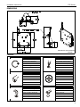
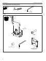
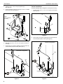
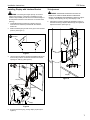
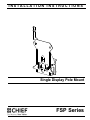
INSTALLATION INSTRUCTIONS
Single Display Pole Mount
FSP Series
FSP Series
Installation Instructions
DISCLAIMER
Milestone AV Technologies, and its affiliated corporations and
subsidiaries (collectively, "Milestone"), intend to make this
manual accurate and complete. However, Milestone makes no
claim that the information contained herein covers all details,
conditions or variations, nor does it provide for every possible
contingency in connection with the installation or use of this
product. The information contained in this document is subject
to change without notice or obligation of any kind. Milestone
makes no representation of warranty, expressed or implied,
regarding the information contained herein. Milestone assumes
no responsibility for accuracy, completeness or sufficiency of
the information contained in this document.
Chief® is a registered trademark of Milestone AV Technologies.
All rights reserved.
WARNING: Use this mounting system only for its intended
use as described in these instructions. Do not use
attachments not recommended by the manufacturer.
WARNING: Never operate this mounting system if it is
damaged. Return the mounting system to a service center for
examination and repair.
WARNING: Do not use this product outdoors.
IMPORTANT ! : The FSP is designed to attach to a
1-1/2" to 2" O.D. pipe, including 1-1/2" NPT (not
included), in either a vertical or horizontal position.
--SAVE THESE INSTRUCTIONS-IMPORTANT SAFETY INSTRUCTIONS!
WARNING: A WARNING alerts you to the possibility of
serious injury or death if you do not follow the instructions.
CAUTION: A CAUTION alerts you to the possibility of
damage or destruction of equipment if you do not follow the
corresponding instructions.
WARNING: Failure to read, thoroughly understand, and
follow all instructions can result in serious personal injury,
damage to equipment, or voiding of factory warranty! It is the
installer’s responsibility to make sure all components are
properly assembled and installed using the instructions
provided.
WARNING: Failure to provide adequate structural strength
for this component can result in serious personal injury or
damage to equipment! It is the installer’s responsibility to
make sure the structure to which this component is attached
can support five times the combined weight of all equipment.
Reinforce the structure as required before installing the
component.
WARNING: Exceeding the weight capacity can result in
serious personal injury or damage to equipment! It is the
installer’s responsibility to make sure the combined weight of
all components attached to the FSP does not exceed 45 lbs
(20.4 kg).
•
2
The weight capacity of the FSP may be LIMITED to the
lowest weight capacity of any other component located
between the FSP and the supporting structure!
Installation Instructions
FSP Series
DIMENSIONS
DIMENSIONS: [MILLIMETERS]
INCHES
LEGEND
Tighten Fastener
Phillips Screwdriver
Apretar elemento de fijación
Destornillador Phillips
Befestigungsteil festziehen
Kreuzschlitzschraubendreher
Apertar fixador
Chave de fendas Phillips
Serrare il fissaggio
Cacciavite a stella
Bevestiging vastdraaien
Kruiskopschroevendraaier
Serrez les fixations
Tournevis à pointe cruciforme
By Hand
Adjust
A mano
Ajustar
Von Hand
Einstellen
Com a mão
Ajustar
A mano
Regolare
Met de hand
Afstellen
À la main
Ajuster
Hex-Head Wrench
Open-Ended Wrench
Llave de cabeza hexagonal
Llave de boca
Sechskantschlüssel
Gabelschlüssel
Chave de cabeça sextavada
Chave de bocas
Chiave esagonale
Chiave a punte aperte
Zeskantsleutel
Steeksleutel
Clé à tête hexagonale
Clé à fourche
3
FSP Series
Installation Instructions
TOOLS REQUIRED FOR INSTALLATION
#2
5/32"
(included)
PARTS
A (2)
[FSP mount]
B (4)
(10-24 x1")
C (4)
(1/2" x .194" x 1/2")
D(1)
5/32"
4
E (1)
[FSB interface bracket
(example only)]
Installation Instructions
FSP Series
FSP Mount Assembly and Installation
INSTALLATION
WARNING: Failure to provide adequate structural strength
for this component can result in serious personal injury or
damage to equipment! It is the installer’s responsibility to
make sure the structure to which this component is attached
can support five times the combined weight of all equipment.
Reinforce the structure as required before installing the
component.
IMPORTANT ! : These instructions assume that a 1-1/2"
to 2" O.D. pipe (not included) has been properly installed
in either a vertical or horizontal position.
The FSP includes tilt bracket that can be repositioned to attach
to a vertical or horizontal pipe. The FSP assembly ships
configured for vertical pole mounting. To change the FSP for
horizontal pole mounting, use the following instructions. To use
the FSP in the vertical configuration, proceed to Vertical
Installation section.
Horizontal Installation
1.
Remove the four Phillips pan head tapping screws from
FSP assembly (A). (See Figure 2)
2.
Detach tilt bracket from FSP (A). (See Figure 2)
3.
Reposition tilt bracket for horizontal pipe/pole mounting.
(See Figure 2)
(Optional) Latching Flag Placement
The latching flag may be moved as necessary.
1.
Remove Phillips undercut machine screw, spacer, Nylock
nut and latching flag from FSP (A). (See Figure 1)
(A)
1
x4
Latching flag
Nylock nut
2
1
Spacer
(A)
3
(Tilt bracket
adjusted for
horizontal
pipe mount)
Figure 2
Figure 1
2.
Re-position latching flag and tighten using Phillips undercut
machine screw, washer and Nylock nut.
5
FSP Series
Installation Instructions
4.
Insert four 1/2" x .194 x 1/2" nylon spacers (C).
(See Figure 3)
Vertical Installation
5.
Secure tilt bracket to FSP (A) using four 10-24 x 1" Phillips
head screws (B). (See Figure 3)
1.
The FSP assembly ships configured for vertical pole mounting.
Install the FSP (A) on 1-1/2" to 2" O.D. pipe (not included).
(See Figure 5)
(B) x 4
5
Note:
Pole not shown
for clarity
Pipe
(A)
Figure 5
2.
4 (C) x 4
Secure FSP (A) to pipe by tightening two button head cap
screws already in place in FSP (See Figure 6)
Figure 3
6.
Slide FSP (A) onto a 1-1/2" to 2" O.D. pipe for horizontal
mounting.
7.
Secure FSP (A) to pipe by tightening two button head cap
screws already in place in FSP. (See Figure 4)
Vertical Configuration
Horizontal Configuration
Pipe
(A)
Pipe
2
x2
(A)
7
x2
Figure 4
6
Figure 6
Installation Instructions
FSP Series
Installing Display with Interface Bracket
Tilt Adjustment
WARNING: IMPROPER HANDLING CAN LEAD TO
WARNING: Exceeding the weight capacity can result in
serious personal injury or damage to equipment! It is the
installer’s responsibility to make sure the combined weight of
all components attached to the FSP does not exceed 45 lbs
(20.4 kg).
1.
Install FSB interface bracket (E) to display using the
instructions and hardware provided with the interface
bracket kit.
2.
Make sure latching flag on FSP mount (A) is in the unlocked
position. (See Figure 7)
DISPLAY FALLING CAUSING SERIOUS PERSONAL
INJURY OR DAMAGE TO EQUIPMENT! Inadequate support
of display while adjusting tilt may cause display to fall!
5.
Adjust tilt by loosening (slightly) tilt adjustment screws on
each side of FSP (A), adjust to desired angle, and tighten tilt
adjustment screws. (See Figure 9)
2 Unlocked
(A)
(A)
(E)
Figure 7
3.
Lift and maneuver display with attached FSB bracket (E) so
that mounting buttons on interface bracket fit into button
openings on FSP (A). (See Figure 8)
4
Locked
5
(B) x 4
Display
Figure 9
Display
(A)
Unlocked
3
(E)
Figure 8
4.
Engage FSP latching flag, locking display in place (See
Figure 8).
7
FSP Series
Installation Instructions
USA/International
Chief, a products division of
Milestone AV Technologies
8800-002568 Rev00
2014 Milestone AV Technologies
www.chiefmfg.com
04/14
Europe
Asia Pacific
A
P
F
A
P
F
A
6436 City West Parkway, Eden Prairie, MN 55344
800.582.6480 / 952.225.6000
877.894.6918 / 952.894.6918
Franklinstraat 14, 6003 DK Weert, Netherlands
+31 (0) 495 580 852
+31 (0) 495 580 845
Office No. 1 on 12/F, Shatin Galleria
18-24 Shan Mei Street
Fotan, Shatin, Hong Kong
P 852 2145 4099
F 852 2145 4477