1
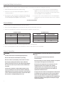
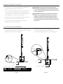
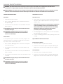
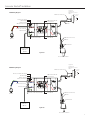
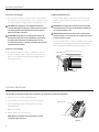
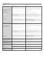
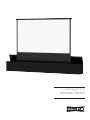
INSTRUCTION BOOK FOR
Ascender Electrol
Important Safety Instructions
When using your video equipment, basic safety precautions should always be followed, including the following:
1. Read and understand all instructions before using.
2. Position the cord so that it will not be tripped over, pulled, or
contact hot surfaces.
3. If an extension cord is necessary, a cord with a current rating at
least equal to that of the appliance should be used. Cords rated
for less amperage than the appliance may overheat.
4. To reduce the risk of electric shock, do not disassemble this
appliance. Contact an authorized service dealer when repair
work is required. Incorrect reassembly can cause electric shock
when the appliance is used subsequently.
5. The use of an accessory attachment not recommended by the
manufacturer may cause a risk of fire, electric shock, or injury to
persons.
Save These Instructions
Pre-Installation
1. The Ascender screen must be installed on a flat, level surface.
2. Remove the white shipping braces (mounted at the end of the arms to the back of the case).
3. Refer to the chart below for minimum overhead clearance required to raise the screen.
4:3 Video Format
16:9 HDTVFormat
Diagonal
Extended Height
Diagonal
Extended Height
100"
94"
106"
86"
120"
104"
119"
92"
150"
121"
133"
99"
180"
139"
159"
112"
200"
149"
4. Allow 12" clearance from back of screen housing to allow arms to extend properly.
5. Remove packing paper from fabric roller. DO NOT use a knife or sharp object to remove the paper.
Screen Operation
CAUTION!
The arms of the screen are under high spring tension.
Do not stand over the screen while it is operating.
Do not sit, stand, or put anything on the screen case door.
Do not apply anything (wood finish, carpet, additional
laminate, etc.) to the screen case door. Any weight added to
the screen case door may cause the screen to malfunction
over time.
2
The case door activates a safety switch inside the screen
case. If you attempt to raise the screen while something is
holding the door shut, the motor will reverse and retract the
screen. The door must be fully closed to activate this switch.
Be sure there is nothing holding the door ajar.
ATTENTION! Les ressorts des bras de l'écran sont fortement
tendus.
Ne vous placez pas devant l'écran pendant son
fonctionnement.
Ne vous asseyez pas, ne vous tenez pas debout, ou ne placez
aucun objet sur la trappe du caisson de l'écran.
Ne couvrez pas la trappe du caisson de l'écran avec un
revêtement en bois, de la moquette, des stratifiés
supplémentaires, etc. Tout poids ajouté à la trappe du
caisson de l'écran pourrait entraîner, avec le temps, le
dysfonctionnement de l'écran.
La trappe du caisson active un interrupteur de sécurité situé
à l'intérieur du caisson de l'écran. Si vous essayez d'élever
l'écran alors que quelque chose tient la trappe fermée, le
moteur rétractera l'écran. La trappe doit être complètement
fermée pour activer cet interrupteur. Vérifiez que la trappe
n'est pas entrouverte.
Screen Operation (continued)
1. The Ascender screen can be operated by the included wall
switch or by optional remote controls (IR or RF).
2. To raise the screen, simply push and release the wall switch. The
screen will stop at its preset position. If you push the switch a
second time while it is rising, the screen will stop. By pushing the
switch a third time the screen will retract and close.
3. To lower the screen from the fully up position, press and release
the wall switch and the screen will retract and close.
4. Test the screen by running it up and down a few times. Be
prepared to stop the screen if needed.
CAUTION! Excessive continuous operation may cause
overheating. If this happens, the motor will shut off until it
cools to normal operating temperature. Standard duty cycle
is 1 min. on / 15 min. off.
ATTENTION! Le fonctionnement continu et excessif peut
provoquer une surchauffe et l'arrêt du moteur. Si cela se
produit, les moteurs s'arrêteront jusqu'à qu'ils se soient
refroidis à la température normale de fonctionnement. Le
cycle de fonctionnement normal est de 1 min. en marche / 15
min. à l'arrêt.
Ascender Electrol® Installation
1. For installations where the Ascender will be set on the floor, the
box must be secured to floor in at least six places (recommended
hardware is #12 x 2" L wood screws)(Figure 1).
2. For installations where the Ascender will be recessed into the
floor, the box must be secured in at least six places
(recommended hardware is #12 x 2" L wood screws)(Figure2).
Floor
Floor
Screw Box Into Floor Stud
Box Frame Support
Figure 1
Figure 2
3
Ascender Electrol® Installation
WARNING: To prevent electrical shock or damage to the low voltage control (LVC), do not apply power to the LVC until all
connections are complete. Make sure power is turned off on all wires before making connections.
AVERTISSEMENT: pour éviter tout choc électrique ou d'endommager le tableau de contrôle basse tension, n'alimentez ce dernier
qu'une fois tous les branchements effectués. Vérifiez qu'aucun câble n'est alimenté avant d'effectuer les branchements.
LOW VOLTAGE CONNECTIONS:
120V/240V Connections:
Wall Switch
AC Power Source
1. Install wall switch where desired.
1. Refer to Figure 3 for electrical connections. Wiring designated as
external is to be completed by installer conforming to local and
national codes.
2. Use 2-conductor 20-24 gauge wire to extend the switch wire to
the required length.
3. Connect the wire from the switch to the wire labeled “wall switch”.
Refer to Figure 3.
CAUTION: Never apply voltage to the wall switch lead or the
LVC will be damaged.
ATTENTION: N'appliquez jamais une tension aux fils du
commutateur mural sinon le tableau de contrôle basse
tension sera endommagé.
Control Panel
NOTE: Must be installed in accordance with the requirements
of the Local Building Codes, the Canadian Electrical Code
(CEC), CAN/CSA C22.1 and the National Electric Code (NEC),
NFPA 70. An appropriate disconnect device shall be
provided as part of the building installation.
2. Use 14-18 gauge wire to connect power to the LVC wires labeled
“AC power input”. Refer to Figure 3.
3. Connect the building ground wire to the ground lug on the metal
housing.
A control panel may be connected to the LVC by using the wall
switch wire lead. The control panel must provide a momentary,
dry contact closure of at least 1/2 second.
Optional Wireless Remote Connections:
1. Use 2-conductor 20-24 gauge wire to connect the control panel
to the wall switch lead.
1. Remove the center cover plate of the LVC box.
2. A momentary closure when the screen is down will be an “up”
command.
Radio Frequency Remote
2. Route the receiver wire through the round plastic bushing and
plug it into the onboard socket marked “EYE”. Refer to Figure 3.
Infrared Remote
3. A momentary closure when the screen is fully extended will be a
“down” command.
1. Remove the center cover plate of the LVC box.
4. A momentary closure while the screen is in motion will be a “stop”
command.
2. Route the receiver wire through the round plastic bushing and
plug it into the onboard socket marked “EYE”. Refer to Figure 3.
CAUTION: Never apply voltage to the wall switch lead or the
LVC will be damaged.
ATTENTION: N'appliquez jamais une tension aux fils du
commutateur mural sinon le tableau de contrôle basse
tension sera endommagé.
4
Ascender Electrol® Installation
120V Wiring Diagram
White (Common)
Green (Ground)
Black (Up)
Red (Down)
White (Common)
Optional IR Or RF
Connection
Single Pull,
Single Throw
Momentary Contact
Switch
Up / Stop /
Down
Off
Black
White (Common)
Black (Hot)
Green (Ground)
Motor
White (Common)
Black
Not Used
Not Used
Power Input
120 VAC /
60 HZ
Figure 3a
Door Microswitch
240V Wiring Diagram
White (Common)
Green / Yellow (Ground)
Brown (Up)
Black (Down)
Blue (Common)
Single Pull,
Single Throw
Momentary Contact
Switch
Up / Stop /
Down
Optional IR Or RF
Connection
Off
Black
Blue (Common)
Brown (Hot)
Green / Yellow (Ground)
Motor
Not Used
White (Common)
Black
Not Used
Power Input
240 VAC /
50 HZ
Figure 3b
Door Microswitch
5
Screen Adjustment
The screen stop positions are preset at the factory. Should it be necessary to adjust for more or less travel proceed as follows (Figure 4).
To Increase Screen Height
To Adjust The Down Position
1. Turn the white limit adjuster counterclockwise one-quarter turn
at a time. Run the screen down about one foot and then back up
to test the stop position. Repeat until the desired position is set.
1. Raise the screen about one foot and stop. Turn the red limit
adjuster counterclockwise one-quarter turn to increase the
down travel.
CAUTION! Do not adjust for more height than what was
ordered. Adjusting too high may cause the arms to lock and
not retract properly. There must be at least 1-1/2 wraps of
fabric on the roller at all times.
ATTENTION: N'effectuez pas de réglage pour obtenir un
déroulement supérieur à celui commandé. Un ajustement
trop élevé peut entraîner le verrouillage des bras et un
enroulement incorrect. 1 à 1/2 tour de toile doit être toujours
maintenu dans le cylindre.
CAUTION! Do not adjust the screen down too far. This will
strain the motor and screen. The lid of the box should just
close when the motor stops.
ATTENTION: Ne déroulez pas trop l'écran. Cela forcera le
moteur et l'écran. Le couvercle du caisson devrait se fermer
lorsque le moteur s'arrête.
2. Turn the red limit adjuster clockwise one-quarter turn at a time to
decrease the amount of down travel. Run the screen down to
test the stop position. Repeat until the desired position is set.
To Decrease Screen Height
1. Turn white limit adjuster clockwise one-quarter turn at a time.
Run the screen up to test the stop position. Lower the screen
about one foot and turn limit adjuster again. Repeat until the
desired position is set.
White Limit Adjuster
Red Limit Adjuster
Figure 4
Keystone Adjustment
The Ascender screen can be adjusted to reduce keystoning of the video image.
This procedure requires two people. One to hold the arms and another to make the adjustments.
1. Raise the screen to the fully extended position.
2. Loosen the two lock nuts on the end of one arm (Figure 5).
Adjusting Nut
3. Turn the adjusting nut and carefully push the arm in the
required direction.
4. Tighten the lock nuts.
5. Repeat steps 2 to 4 for the other arm.
NOTE: Make sure that the screen surface does not rub
against the edge of the case.
Lock Nuts
Figure 5
6
Troubleshooting
Symptom
Screen will not operate or will
not go “down”.
Cause
Solution
Tripped circuit breaker.
Reset circuit breaker.
Check above. Tighten all loose wire connections. Correct any
improper connections.
No power to operating switch or junction.
Motor does not hum.
Motor hums.
“Down” Position.
Check for power across black and white leads.
Power at junction box
Thermal overload tripped.
Let motor cool down for 15 minutes. Try again.
Broken wire in the “down” position.
Check for continuity. Cut off old splice and reconnect.
Defective motor, limit switch or capacitor.
Replace motor assembly.
NOTE: Motor is a sealed assembly.
Capacitor burned out.
Replace motor assembly.
Tripped circuit breaker.
Reset circuit breaker.
Screen will not move “up”
Motor does not hum
Check above. Tighten all loose wire connections. Correct any
improper connections.
No power to operating switch or junction.
“Up” Position.
Check for power across black and white leads.
Power at junction box
Thermal overload tripped.
Let motor cool down for 15 minutes. Try again.
Broken wire in the “up” position.
Check for continuity. Cut off old splice and reconnect.
Defective motor, limit switch or capacitor.
Replace motor assembly.
NOTE: Motor is a sealed assembly.
Capacitor burned out.
Replace motor assembly.
Incorrect stopping position in
downward direction.
“Down” limit switch out of adjustment.
See installation instructions.
Incorrect stopping position in
upward direction.
“Up” limit switch out of adjustment.
Adjust “up” limit switch. See installation instructions
Noise.
rinding due to foreign object in screen rubbing
G
on roller or fabric.
Remove foreign object.
NOTE: Screen will operate with
a low pitched hum.
Gear noise.
Replace motor assembly.
Coasting.
Defective brake.
Replace motor assembly.
Motor hums.
7
LIMITED ONE YEAR WARRANTY ON DA-LITE PRESENTATION PRODUCTS
Milestone AV Technologies LLC warrants certain Da-Lite branded products to the original purchaser only, to be free from defects in
materials and workmanship for a period of one (1) year from the date of purchase by the original purchaser; provided they are properly
operated according to Da-Lite's instructions and are not damaged due to improper handling or treatment after shipment from the
factory.
This warranty does not apply to equipment showing evidence of misuse, abuse or accidental damage, or which has been tampered
with or repaired by a person other than authorized Da‑Lite personnel.
Da-Lite’s sole obligation under this warranty shall be to repair or to replace (at Da-Lite’s option) the defective part of the merchandise.
Returns for service should be made to your Da-Lite dealer. If it is necessary for the dealer to return the screen or part to Da-Lite,
transportation expenses to and from Da-Lite are payable by the purchaser and Da-Lite is not responsible for damage in shipment.
To protect yourself against damage or loss in transit, insure the product and prepay all transportation expenses.
TO THE MAXIMUM EXTENT PERMITTED BY APPLICABLE LAW, THIS WARRANTY IS IN LIEU OF ALL OTHER WARRANTIES, EXPRESS
OR IMPLIED, INCLUDING WARRANTIES AS TO FITNESS FOR USE AND MERCHANTABILITY. Any implied warranties of fitness for use,
or merchantability, that may be mandated by statute or rule of law are limited to the one (1) year warranty period. This warranty gives
you specific legal rights, and you may also have other rights, which vary from state-to-state. TO THE MAXIMUM EXTENT PERMITTED
BY APPLICABLE LAW, NO LIABILITY IS ASSUMED FOR EXPENSES OR DAMAGES RESULTING FROM INTERRUPTION IN OPERATION
OF EQUIPMENT, OR FOR INCIDENTAL, DIRECT, OR CONSEQUENTIAL DAMAGES OF ANY NATURE.
In the event that there is a defect in materials or workmanship of a Da-Lite product, you may contact our Sales Partners at PO Box 137,
Warsaw, IN 46581-0137, (574) 267-8101, (800) 622-3737.
IMPORTANT: THIS WARRANTY SHALL NOT BE VALID AND DA-LITE BRANDED PRODUCTS SHALL NOT BE BOUND BY THIS
WARRANTY IF THE PRODUCT IS NOT OPERATED IN ACCORDANCE WITH THE DA-LITE WRITTEN INSTRUCTIONS.
Keep your sales receipt to prove the date of purchase and your original ownership.
A Milestone AV Technologies Brand
3100 North Detroit Street
Warsaw, Indiana 46582
P: 574.267.8101 or 800.622.3737
F: 574.267.7804 or 877.325.4832
E: [email protected]
www.da-lite.com
DL–0279 (Rev. 3) 09.14
© 2014 Milestone AV Technologies LLC. Printed in U.S.A.
85267