1
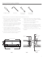
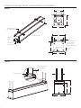
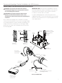
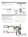
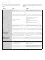
INSTRUCTION BOOK FOR
Tensioned Advantage® Electrol®
Important Safety Instructions
Pre-Installation
When using your video equipment, basic safety precautions
should always be followed, including the following:
1. Carefully unpack case from shipping carton.
1. Read and understand all instructions before using.
2. Set aside the Installation Kit. Items inside will be used
during installation.
2. Position the cord so that it will not be tripped over, pulled,
or contact hot surfaces.
3. Make sure to recheck measurement of case for proper
installation clearance.
3. If an extension cord is necessary, a cord with a current rating
at least equal to that of the appliance should be used. Cords
rated for less amperage than the appliance may overheat.
4. Remove any protective foam covering the outside
of the case.
4. To reduce the risk of electric shock, do not disassemble this
appliance. Contact an authorized service dealer when repair
work is required. Incorrect reassembly can cause electric
shock when the appliance is used subsequently.
5. The use of an accessory attachment not recommended by
the manufacturer may cause a risk of fire, electric shock, or
injury to persons.
5. For shipping purposes, foam is also inserted between the
roller brackets and endcaps (Figure 1). Remove these foam
blocks from the ends.
6. Remove the hanger brackets from the top of the case
using a 1/2" wrench. Do not discard the hardware; it will be
used during case installation to re-attach the hanger
brackets for mounting.
Save These Instructions
Tools Required for Installation
Case Installation
1. Hang case and attach to support structure with bolts. See
Suggested Methods of Installation.
2. Tighten bolts until trim flange is flush with ceiling.
1/2“ Open Wrench
or Socket Driver
1/8” Hex Key
(included)
NOTE: For proper operation, screen assembly must be level
after installation.
3. Remove 2 screws to open junction box. Install electrical
connections that apply to your unit. Make sure to review the
wiring diagram for proper hook up. Replace junction box
cover and secure with 2 screws.
NOTE: Must be installed in accordance with the requirements
of the Local Building Codes, the Canadian Electrical Code
(CEC), CAN/CSA C22.1 and the National Electric Code (NEC),
NFPA 70.
If your case was ordered in advance of the screen and
roller assembly, your installation is now complete. Continue
to step 4 if your Tensioned Advantage Electrol was ordered
as a complete unit.
4. Use supplied 1/8" hex key to remove silver shipping brackets
attached to slat and screen case.
5. Test installation by running screen up and down a few times.
Be prepared to stop screen should any objects obstruct the
movement of the screen. To prevent damage to the motor,
the standard duty cycle is 1 minute on and 3 minutes off.
2
Screen And Roller Assembly Installation
Tools required for screen and roller assembly:
#2 Phillips Screwdriver
1/8“ Hex Key
1/2“ Open Wrench
or Socket Driver
1/4“ Open Wrench
or Socket Driver
Follow these steps if your screen and roller assembly was ordered separately from the case.
1. Remove the access door. First, remove the 2 screws from the
ends using a #2 phillips screwdriver. Be sure to support the
door during this step to avoid injury. Then lift the door slightly
and pull away from the edge of the case (Figure 1).
2. Carefully unpack screen and roller assembly. Use supplied 1/8"
hex key to remove shipping brackets attached to slat. Remove
fabric and roller assembly from shipping board using a 1/2"
wrench. Leave packing paper on roller.
3. To install screen and roller assembly, loosen (but do not
remove) four 1/4-20 nuts securing pin end bracket (opposite
end from the junction box) to the case housing. Slide the pin
end bracket towards the end of the case (Figure 2).
5. Moving to the pin end of the case, slide the pin end bracket
until the hole fits securely over the pin. Tighten the 1/4-20 nuts
on the pin end bracket securely (Figure 2).
6. Complete electrical hook-up by snapping motor wire
connector into case connector (Figure 3).
8. Test installation by running screen up and down a few times.
Be prepared to stop screen should any objects obstruct the
movement of the screen. To prevent damage to the motor, the
standard duty cycle is 1 minute on and 3 minutes off.
9. Re-install the access door. Procedure is the reverse of step 1
listed above.
4. Insert the motor end square shaft into the motor end bracket
(junction box end) and secure with the clip (Figure 3).
Clip
1/4-20 Nuts
Motor Power
Connector
Motor
Access Door Screws
Foam Blocks
Motor Mount
Bracket
Figure 1
Figure 2
Figure 3
3
Tensioned Advantage® Electrol® Suggested Methods of Installation
Method 1
6 1/16"
6 7/16"
7 3/4"
Variable Position
Mounting Bracket
8"
Audience Side
Motor
End
6 1/16"
3/8" Threaded Rod
(Not Included)
Attached To
Mounting Bracket
Electrical
Junction Box
6 3/8"
Self-Trimming
Flange
Finished
Ceiling
7 3/4"
Method 2
3/8" Threaded Rod
(Not Supplied)
Hanger Bracket
3 7/16"
7 7/16"
6 7/16"
7 3/4"
4
Screen Adjustment for 120V Screens
If your Tensioned Advantage Electrol was ordered as a complete unit, the up and down limits were pre-set by Da-Lite. If your screen and
roller assembly was ordered separately from the case, or if general adjustment is needed, please follow the steps below and refer to the
120V Wiring Diagram.
1. Locate the wall switch and remove the cover plate from the
wall switch and remove the switch from the junction box.
2. Locate the two tactile buttons on the back of the switch.
They are black round buttons on silver plates. See 120V
Wiring Diagram.
3. To adjust the down limit switch, press and hold the down
tactile button until the LED on the back of the switch turns
solid red. This will put the motor in limit set mode. Turn the
wall switch over and use the down button on the front of the
switch. Press and hold the down button until the desired
down position is reached. If you travel too far down, press the
up button to move the screen upward. If you press and let go
of either the up or down buttons, the motor will do a small
jog in that direction for fine adjustment of the screen. Once
the desired position is reached, turn the switch over; press
and hold the down tactile button until the LED on back of
switch blinks red twice. The down limit is now set.
changes will be saved. If this occurs, return to step 3 for down
limit adjustment or step 4 for up limit adjustment.
4. To adjust the up limit switch, press and hold the up tactile
button until the LED on the back of the switch turns solid
green. This will put the motor in limit set mode. Turn the wall
switch over and use the up button on the front of the switch.
Press and hold the up button until the desired up position is
reached. If you travel too far up, press the down button to
move the screen downward. If you press and let go of either
the up or down buttons, the motor will do a small jog in that
direction for fine adjustment of the screen. Once the desired
position is reached, turn the switch over; press and hold the
up tactile button until the LED on back of switch blinks green
twice. The up limit is now set.
CAUTION: Adjusting the down limit switch for less drop
by more than 6" can cause the screen surface to lose
proper tensioning.
CAUTION: Do not adjust for more drop than what was
ordered. At least 1–1/2 wraps of fabric must remain on
the roller. This screen comes standard with 12" black
at the top.
ATTENTION! N'effectuez pas de réglage pour obtenir un
déroulement supérieur à celui commandé. Au moins 1 à
1/2 tour de toile doit être maintenu sur le cylindre. Ce
écran est doté de série d'une bande noire supérieure de
30,5 cm (12 po).
ATTENTION! LE FAIT D'AJOUTER NE DÉROULEZ PAS
TROP L'ÉCRAN PLUS DE 15 CM (6PO) AUX
INTERRUPTEURS DE FIN DE COURSE PEUT FAIRE
PERDRE LA BONNE TENSION À LA SURFACE DE L'ÉCRAN.
5. To test the limit switch settings, press and release the up or
down buttons on the switch to operate the screen.
6. Replace the switch and cover plate on the wall.
NOTE: If the screen is in limit set mode and no buttons are
pushed for 20 seconds, the LED on the back of the wall
switch will turn off, the motor will return to run mode and no
IMPORTANT NOTE: The wall switch is REQUIRED to make
any limit switch adjustments, even if a third party control
system is used. Therefore, it is advised to wire the switch or
provide a 3-conductor connection that is accessible.
Screen Adjustment for 220V/240V Screens
C AUTION: Adjusting the down limit switch for less drop
by more than 6” can cause the screen surface to lose
proper tensioning.
1. Remove the cover plate from the 3-button wall switch and
remove the switch from the junction box.
2. Locate small 3-position switch on back of wall switch. See
Figure 5 for 120V screens or Figure 8 for 220/240V screens.
3. To adjust the down limit switch, slide the 3-position switch to
the down position. Press and hold the down button to run the
screen down to the desired stop position. Release the button
to stop the screen. DO NOT PUSH THE STOP BUTTON.
CAUTION: Do not adjust for more drop than what was
ordered. At least 1–1/2 wraps of fabric must remain on the
roller. This screen comes standard with 12" black at the
top. See the specification data sheet for details.
ATTENTION! N'effectuez pas de réglage pour obtenir un
déroulement supérieur à celui commandé. Au moins 1 à
1/2 tour de toile doit être maintenu sur le cylindre. Ce
écran est doté de série d'une bande noire supérieure de
30,5 cm (12 po).
4. When the screen is in the desired down position, slide the
3-position switch to the off (center) position. The down limit
switch is now set.
5. To adjust the up limit switch, slide the 3-position switch to the
up position. Press and hold the up button to run the screen
up to the desired stop position. Release the button to stop
the screen. DO NOT PUSH THE STOP BUTTON.
ATTENTION! Le fait d'ajouter ne déroulez pas trop l'écran
plus de 15 cm (6po) aux interrupteurs de fin de course
peut faire perdre la bonne tension à la surface de l'écran.
6. When the screen is in the desired up position, slide the
3-position switch to the off (center) position. The up limit
switch is now set.
7. To test limit switch setting, make sure the 3-position switch is
in the off (center) position. Press and release the up or down
button on the wall switch to operate the screen.
8. Replace switch and cover plate on the wall.
NOTE: If stop button is pressed, the wall switch will reverse
direction. To correct this, press the stop button again. This will
reset the switch. You will have to re-set both the up and the
down limit settings.
IMPORTANT NOTE: The wall switch is REQUIRED to make
any limit switch adjustments, EVEN if a third party control
system is used. Therefore, it is advised to wire the switch or
provide a 4-conductor connection that is accessible.
5
Tensioned Advantage® Electrol® Installation for 120V Screens
120V Wiring Diagram
UP
IMPORTANT NOTE: The wall switch is REQUIRED to make any
limit switch adjustments, EVEN if a third party control system is
used. Therefore, it is advised to wire the switch or provide a
3-conductor connection that is accessible..
3-conductor 20–24 gauge wire can be used in place of the
supplied RJ-14 cable to connect the wall switch. Connect the BUS
terminals on the wall switch to the corresponding BUS terminals
on the splitter board.
STO
P
DO
WN
Led
Up Limit
Tactile Button
RJ-22
Inputs
UP
Up (Dry Contact)
Down (Dry Contact)
Common (Both)
Bus (Bus)
5V (Bus)
RJ-22
Output
STOP
DOW
N
UP
P
5V
COM
BUS
STO
Bus
Down Limit
Tactile Button
DO
WN
Front of
Wall Switch
Back of
Wall Switch
RJ-22
Jack
RJ-45
Receptacle
5V
COM
BUS
RJ-22 Jack
(Connection to
Wall Switch)
5V
COM
BUS
Installation Video
To view a video of this installation,
visit http://youtu.be/t2ZQ9PVAhEg
or use the QR code below.
RJ-45 Jack
Data
Cable
Power
Wire
White
(Common)
Black
(Hot)
Green (Ground)
(Ground–Must be Connected
to Building Ground)
Power Input 120VAC / 60Hz
RJ-14 Pin-Outs (Tab Is Facing Up)
RJ-22 Pin-Outs (Tab Is Facing Up)
+12V
Bus (RP Data)
White
Bus (RP Data)
Yellow
RQ Data
Green
RQ Data
Green
+5V
Ground
Red
Black
Supplied RJ-14 cable
6
Blue
+5V
Red
Ground
Black
RQ Clock
White
Standard RJ-22 can be used in place of RJ-14 cable
RJ-45 Pin-Outs (Tab Is Facing Up)
Manual 2
+12V
Bus (RP Data)
RQ Data
+5V
Ground
RQ Clock
Manual 1
Brown
Blue
Yellow
Green
Red
Black
Orange
Purple
Tensioned Advantage® Electrol® Installation for 120V Screens
120V Wiring Diagram with Optional Built-In Video Projector Interface
CAUTION: The projector must be turned off before
connecting the trigger wires to the projector. Failure to
do so may damage the controller.
IMPORTANT NOTE: The wall switch is REQUIRED to make any
limit switch adjustments, EVEN if a third party control system is
used. Therefore, it is advised to wire the switch or provide a
3-conductor connection that is accessible.
ATTENTION: Le projecteur doit être éteint avant de
brancher les fils de déclenchement à celui-ci. Tout
manquement à cette instruction pourrait endommager le
contrôleur.
3-conductor 20–24 gauge wire can be used in place of the
supplied RJ-14 cable to connect the wall switch. Connect the BUS
terminals on the wall switch to the corresponding BUS terminals
on the splitter board.
Use 2-conductor 18–24 gauge wire to extend the low voltage
connection from the projector’s 5 or 12-volt screen trigger output
to the length required to reach the VPI. When extending the low
voltage connection from the projector’s screen trigger output
polarity does not matter. The red and black wires from the VPI
are interchangeable.
UP
STO
P
DO
WN
Led
Up Limit
Tactile Button
RJ-22
Inputs
UP
Up (Dry Contact)
Down (Dry Contact)
Common (Both)
Bus (Bus)
5V (Bus)
RJ-22
Output
STOP
DOW
N
UP
5V
COM
BUS
STO
P
Down Limit
Tactile Button
Bus
DO
WN
Front of
Wall Switch
Back of
Wall Switch
RJ-22
Jack
RJ-45
Receptacle
5V
COM
BUS
RJ-22 Jack
(Connection to
Wall Switch)
5V
COM
BUS
VPI Trigger
Module
RJ-45 Jack
Data
Cable
Power
Wire
Black
Red
White
(Common)
Black
(Hot)
Green (Ground)
(Ground–Must be Connected
to Building Ground)
Power Input 120VAC / 60Hz
5/12 Volt
Screen Trigger
on Projector
7
Tensioned Advantage® Electrol® Installation for 220/240V Screens
240V Wiring Diagram
ILT RJ-9 Pin-Outs (Tab Is Facing Up)
IMPORTANT NOTE: The wall switch is REQUIRED to make any
limit switch adjustments, EVEN if a third party control system is
used. Therefore, it is advised to wire the switch or provide a
4-conductor connection that is accessible.
IR or Up
Black
Ground Common
Red
+5V
Green
Data or Down
White
Blue (Common)
Power Input
240VAC / 50Hz
Brown (Hot)
Motor
RJ9
RJ9
UP
UP DN
Green
GND
+5V
STOP
Green
UP
+5V
COM
DN
Ground to Case
NOTE: Ground–Must be
Connected to Building
Ground
Splitter
Dry Contacts
DOWN
3-POSITION
SWITCH
RJ9
Front of Wall
Switch
Back of
Wall Switch
240V Wiring Diagram with Optional Built-in Video Projector Interface
CAUTION: The projector must be turned off before
connecting the trigger wires to the projector. Failure to
do so may damage the controller.
ATTENTION: Le projecteur doit être éteint avant de
brancher les fils de déclenchement à celui-ci. Tout
manquement à cette instruction pourrait endommager le
contrôleur.
1. Use 2-conductor 20-24 gauge wire to extend the low voltage
connection from the projector’s 5 or 12-volt screen trigger
output to the length required to reach the VPI. When
extending the low voltage connection from the projector’s
screen trigger output, be sure to maintain the proper polarity.
The red wire from the VPI is the “signal” and the black wire
from the VPI is the “ground”.
2. Connect the wires from the VPI that are labeled “Low Voltage
Connection” to the end of the extended screen trigger wires
above.
IMPORTANT NOTE: The wall switch is REQUIRED to make
any limit switch adjustments, EVEN if a third party control
system is used. Therefore, it is advised to wire the switch or
provide a 4-conductor connection that is accessible.
Brown (Hot)
240VAC/ 50Hz
Power Source
Green/Yellow
(Ground)
Green/Yellow (Ground)
Brown (Down)
Blue (Common)
Black (Up)
Blue (Common)
White
Red
Front of Wall
Switch
Back of
Wall Switch
Black
5/12 Volt Screen Trigger
on Projector
Black
8
Red
Troubleshooting
Visit www.da-lite.com to find installation and troubleshooting
tutorials. You will also find a link to Live Chat for interactive
support.
Symptom
You can contact us by email at [email protected] or by phone at
800.622.3737 or 574.267.8101 with any additional troubleshooting
questions.
Cause
Solution
Incorrect line voltage.
Verify 115-125V (or 220-240V). If insufficient voltage, rewire
incoming electric line.
Blown fuse.
Replace fuse.
Tripped circuit breaker.
Reset circuit breaker.
creen will not operate
S
and motor does not hum.
Check above. Tighten all loose wire connections.
Correct any improper connections.
No power to operating switch
or junction.
Down Position
Check for power across black and white leads.
Up Position
Check for power across red and white leads.
Thermal overload tripped.
Let motor cool down for 15 minutes. Try again.
Screen will not operate
and motor does not hum.
Broken wire in the “down” or “up” position.
Check for continuity. Cut off old splice and reconnect.
Power at junction box.
Defective motor, limit switch or capacitor.
Replace motor assembly. NOTE: Motor is a sealed assembly.
Capacitor burned out.
Replace motor assembly.
Limit switch out of adjustment.
See Screen Adjustment section.
Squeaking, rubber end plug rubbing on motor.
Center roller in case.
rinding. Foreign object in screen
G
rubbing on roller or fabric.
Remove.
Gear noise.
Replace motor assembly.
Defective brake.
Replace motor assembly.
Screen not installed properly.
Check for level and plumb.
Fabric has backed up inside case.
djust “down” limit switch slowly until roller is exposed and
A
wrinkle comes out, then readjust for proper drop.
Fabric is damaged.
Replace fabric.
Screen does not stop
at correct position.
Noise.
NOTE: Screen will operate
with a low pitched hum.
Coasting.
Fabric hangs crooked.
9
10
11
LIMITED FIVE YEAR WARRANTY ON DA-LITE TENSIONED ADVANTAGE® ELECTROL®, ADVANTAGE® ELECTROL®,
TENSIONED LARGE ADVANTAGE® ELECTROL®, LARGE ADVANTAGE® ELECTROL®, TENSIONED CONTOUR® ELECTROL®
AND CONTOUR® ELECTROL® PRODUCTS ONLY
Milestone AV Technologies LLC warrants these Da-Lite branded products to the original purchaser only, to be free from defects in materials and
workmanship for a period of five (5) years from the date of purchase by the original purchaser; provided they are properly operated according
to Da-Lite’s instructions and are not damaged due to improper handling or treatment after shipment from the factory.
This warranty does not apply to equipment showing evidence of misuse, abuse or accidental damage,
or which has been tampered with or repaired by a person other than authorized Da‑Lite personnel.
Da-Lite’s sole obligation under this warranty shall be to repair or to replace (at Da-Lite’s option) the defective part of the merchandise. Returns
for service should be made to your Da-Lite dealer. If it is necessary for the dealer to return the screen or part to Da-Lite, transportation expenses
to and from Da-Lite are payable by the purchaser and Da-Lite is not responsible for damage in shipment.
To protect yourself against damage or loss in transit, insure the product and prepay all transportation expenses.
TO THE MAXIMUM EXTENT PERMITTED BY APPLICABLE LAW, THIS WARRANTY IS IN LIEU OF ALL OTHER WARRANTIES, EXPRESS
OR IMPLIED, INCLUDING WARRANTIES AS TO FITNESS FOR USE AND MERCHANTABILITY. Any implied warranties of fitness for use, or
merchantability, that may be mandated by statute or rule of law are limited to the five (5) year warranty period. This warranty gives you specific
legal rights, and you may also have other rights, which vary from state-to-state. TO THE MAXIMUM EXTENT PERMITTED BY APPLICABLE
LAW, NO LIABILITY IS ASSUMED FOR EXPENSES OR DAMAGES RESULTING FROM INTERRUPTION IN OPERATION OF EQUIPMENT,
OR FOR INCIDENTAL, DIRECT, OR CONSEQUENTIAL DAMAGES OF ANY NATURE.
In the event that there is a defect in materials or workmanship of a Da-Lite product, you may contact our Sales Partners at PO Box 137, Warsaw,
IN 46581-0137, (574) 267-8101, (800) 622-3737.
IMPORTANT: THIS WARRANTY SHALL NOT BE VALID AND DA-LITE BRANDED PRODUCTS SHALL NOT BE BOUND BY THIS
WARRANTY IF THE PRODUCT IS NOT OPERATED IN ACCORDANCE WITH THE DA-LITE WRITTEN INSTRUCTIONS.
Keep your sales receipt to prove the date of purchase and your original ownership.
A Milestone AV Technologies Brand
3100 North Detroit Street
Warsaw, Indiana 46582
P: 574.267.8101 or 800.622.3737
F: 574.267.7804 or 877.325.4832
E: [email protected]
www.da-lite.com
DL–0115 (Rev. 5) 10.14
© 2014 Milestone AV Technologies LLC. Printed in U.S.A.
84215