1
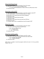
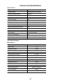
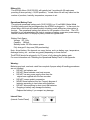
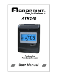
ATR240
Top Loading
Time Card Recorder
User Manual
Lithium Battery Caution:
The circuit board on this terminal is populated with a lithium battery to protect data
or programs stored in the Random Access Memory (RAM). Do not, under any
circumstances, attempt to replace the lithium battery in the terminal. Failure to
comply may void your warranty. Battery replacement should be done by qualified
personnel wearing the proper eye protection.
CAUTION: Danger of explosion if the battery is incorrectly replaced. Replace only
with the same or equivalent type recommended by the manufacturer. Discard used
batteries according to the manufacturer’s instruction.
This product utilizes a battery that contains Perchlorate Material.
Perchlorate Material – special handling may apply, See
www.dtsc.ca.gov/hazardouswaste/perchlorate
Table of Contents
Before You Start!.......................................................................1
What’s In the Box....................................................................1
Clock Overview .........................................................................3
Top View .................................................................................3
Front View ..............................................................................3
Rear View ...............................................................................4
Initial Setup ...............................................................................5
Features and Specifications ....................................................7
Clock Features .......................................................................7
Clock Specifications................................................................7
Miscellaneous.....................................................................7
Ribbon Life .............................................................................8
Operational Battery Pack........................................................8
Internal View ...........................................................................8
Re-setting Time Recorder to Factory Defaults........................9
Troubleshooting........................................................................9
Frequently Asked Questions.................................................10
Maintenance ............................................................................ 11
Replacing the Ribbon Cassette ............................................ 11
Replacing the Circuit Board Batteries...................................12
Installing the Operational Battery Pack.................................13
Cleaning the ATR240............................................................13
Appendix ...............................................................................14
Connecting External Signal Devices (Bells & Horns) ...........14
Wall Mounting Instructions....................................................15
Supplies, Parts & Accessories ..............................................15
Acroprint® Limited Warranty.................................................16
Product Registration Card .....................................................17
Before You Start!
What’s In the Box
• ATR240 Time Recorder
• (2) Clock Cover Keys
• 18vDC Switching Power Supply
• User Manual
• (25) Sample ATR241 Weekly Time Cards
• Clock Wall Mounting Template
(Also available for download at http://support.acroprint.com/)
• (2) Mounting Screws
• (2) Plastic Wall Anchors
1) Unpack clock. Inspect clock for any damages that may have occurred during
shipment. Check box contents for any missing items. If any damages are found or
if any parts are missing please contact Acroprint Customer Service at (800)
334-7190.
2) Connect the ATR240 power adapter and plug it into a wall outlet to turn the clock on.
3)
If this is the first time you’ve turned the clock on, open the Ribbon Access Door with the key
and, using a ball point pen, press the Reset button.
Do not attempt to service the ATR240 yourself. Disassembling the clock will void
the warranty. Always follow the instructions in the user guide.
• Do not place the clock in direct sunlight as this could discolor the housing over time.
• The clock is designed for indoor use in a temperature range of 32-104º F (0-40º C).
The clock is not waterproof or shockproof. Keep the clock away from heat sources
such as radiators. Avoid dusty environments or exposure to chemicals.
• The clock may be placed upright on a solid surface or mounted to a wall with mounting
screws. Use the enclosed template & screws for wall mounting. Avoid locations
where the device will be subject to vibrations and shock such as a slamming door.
• The clock warranty does not cover defects or damages caused by improper installation,
improper storage, abuse, ordinary wear, or unauthorized service.
Page 1
Time Recorder Mode Settings
Mode
Setting
Values
Default
Value
01
Year
2000 – 2099
Year of Mfg
02
Date
1-12 Mo, 1-31 Date
01, 01
03
Time
1-23 Hr, 0-59 Min
12 : 00
04
End of Day Change Time
1-23 Hr, 0-59 Min
00 : 00
00: first row blank
01: prints on 1st row
00
00: Mthly, 01: Wkly
01=Mon…07=Sun
01
07
12 or 24 Hr
12
05
Set Card Format
(Set “00” for ATR241 cards)
06
Pay Period Type
*End Day of Wkly P.Period
Must set 07 for Wkly Card
07
08
Clock Display Format
Adjust Printing Position
Max: 6mm Vert/Horiz adj.
Increase #’s to move up/right
09
10
08,08
vert, horiz
DST Start Month / Date
DST Start Time
1-12 Mo, 1-31 Date
00-23 Hr
00, 01
02
DST End Month / Date
DST End Time
1-12 Mo, 1-31 Date
00-23 Hr
00, 01
02
00: 24 Hr
01: Decimal Hrs
02: 12 Hr (pm)
02
00: On, 01: Off
01
Print Format
(Independent of display format)
11
00-15: Vertical Axis
00-30: Horiz. Axis
Time Card Recognition
Note: Turn “On” for Mthly cards
Note: Pressing “All-Reset” on the control panel will reset all Time Recorder
settings to their factory defaults.
Page 2
Clock Overview
Top View
Front View
• Battery Status Indicator: A fully charged Battery will have (5) bars.
• DST Icon: displays when exiting programming mode when DST is turned on.
• Each blink of the colon is one sec.
Page 3
Rear View
Page 4
Initial Setup
Setting Year
1. Remove top cover
a. Locate buttons at the top of the clock labeled P4, P5 and P6
i. P4 changes values down
ii. P5 changes values up
iii. P6 is used to save and select modes
2. Locate the Setup (programming) switch. Move the switch to the left position, you are now
in setup mode
3. The mode indicator “01” will be flashing, press P6 to select
4. Press P4 or P5 to select the current year
5. Press P6 to Save
Setting Month/Date
6. The mode indicator “02” will be flashing, press P6 to select
7. Press P4 or P5 to select the current month
8. Press P6 to save
9. Press P4 or P5 to select the current date
10. Press P6 to save
Setting Time
11.
12.
13.
14.
15.
The mode indicator “3” will be flashing, press P6 to
Press P4 or P5 to select the current hour
Press P6 to save
Press P4 or P5 to select the current minute
Press P6 to save
select
Setting Day Advance Time
16. The mode indicator “04” will be flashing, press P6 to select
17. Complete steps 11-15
Setting Pay Period
18. The mode indicator “05” will be flashing, press P5 to switch to mode “06”
19. The mode indicator “06” will be flashing, press P6 to select
20. Select the pay period type by pressing P4 or P5
a. If the pay period is monthly select 00
b. If the pay period is weekly select 01
21. Press P6 to save
22. To select the end of the weekly pay period you must select 07
23. Press P6 to save
Page 5
Setting Clock Display Format
24. The mode indicator “07” will be flashing, Press P6 to select
25. Press P4 or P5 to select the clock display format
a. You can choose between the 12 hour or 24 hour (military time) format
26. Press P6 to save
Setting Start and End of DST
27. The mode indicator “08” will be flashing, press P5 to switch to mode “09”
28. The mode indicator “09” will be flashing, press P6 to select
29. Press P4 or P5 to select the correct month (US-March)
30. Press P6 to save
31. Press P4 or P5 to select the correct date
32. Press P6 to save
33. Press P4 or P5 to select the correct start time (US-2am)
34. Press P6 to save
35. Complete steps 29-34 to complete the set up for the end of DST
Setting Print Format
36. The mode indicator “10” will be flashing, press P6 to select
37. Press P4 or P5 to select the correct print format
a. 00 – 24 hour (Military Time)
b. 01 – Decimal Hours
c.
02 – 12 hours (pm)
38. Press P6 to save
Setting Time Card Recognition
39. The mode indicator “11” will be Flashing, press P6 to select
40. Press P4 or P5 to select the correct the correct time card format
a. 00 – Monthly, Semi-Monthly
b. 01 – Weekly, Bi-Weekly
41. Press P6 to save
Initial setup is complete. Locate the program switch and move it to the up position.
Replace top cover.
Page 6
Features and Specifications
Clock Features
Display Language
English
Operation Mode
Stand-alone (No PC Interface)
Operational Battery Backup
Optional
Auto Card Feeder
Yes
Printing Method
9-Pin Dot Matrix
Two Color Printing
Yes
Perpetual Calendar
Yes
Auto Fix Positioning
Yes
Power Failure Printing
Yes
Power Failure Memory Retention
Yes
Display Format
12 or 24 hour
Print Format
12 hr, 24 hr, decimal time
External Alarm
Connection Available
Auto Column Changing
Yes
Compatible with Wkly Time Card
Yes (Card Recognition Off)
Card Recognition (front/back)
Yes
Clock Specifications
Miscellaneous
Input Voltage
DC 18v
Input Current
1.5A
Anti-static Strength
< 15KV
Operational Relative Humidity
10 – 60%
Operational Temperature
0 – 40º C (32 – 104º F)
Storage Relative Humidity
10 – 80%
Storage Temperature
-10 – 60º C (14 – 140º F)
Dimensions (Clock)
196 (w) x 239 (h) x 126 (d) mm
Dimensions (Boxed)
266 (w) x 283 (h) x 208 (d) mm
Weight (Clock Only)
4.0 Lb
Weight (Boxed)
5.6 Lb
Operational Battery Pack Wt.
0.7 Lb
Time Card Dimension
185mm L x 86mm W
Time Card Weight
300#
Circuit Board Battery
CR2032 (2 yr life)
Page 7
Ribbon Life
The ATR242 ribbon (39-0135-000) will typically last 3 months with 50 employees
punching 6 times per day (~18,000 punches). Actual ribbon life will vary based on the
number of punches, humidity, temperature, exposure to air.
Operational Battery Pack
The optional operational battery pack (58-0114-000) is a 12 cell NiMH (Nickel Metal
Hydride) battery pack that recharges when the ATR240 is plugged in. In the event of a
power failure the clock will instantly switch to battery power without any interruption in
service. The operational battery pack allows for full operation of the clock. The LCD
backlight is not activated when the clock is running on battery power as a power saving
feature, however the LCD display is plainly visible in a lighted room.
Battery Pack Specs:
Voltage: DC 14.4v
Capacity: 1800mA
Standby mode: 30-36hr reserve power
Fully charged: 5 days use (300 punches/day)
Note: Actual battery life depends on many factors such as battery age, temperature,
discharge history, etc., and can vary greatly depending on these factors.
The ATR240 should be plugged in for 12 hours to fully charge the battery pack.
For more information see “Installing the Operational Battery Pack” in the Appendix.
Warning:
Batteries may leak, overheat, catch fire or explode if proper safety & handling procedures
are not followed:
• DO NOT get batteries wet
• DO NOT place batteries near heat sources
• DO NOT use any power supply other than the
original one supplied with the time recorder.
• DO NOT inverse polarity connection
• NEVER throw batteries into fire. Properly dispose of
batteries according to local rules and regulations.
• DO NOT allow anything to short circuit the batteries
•
Dropping a battery may damage the battery.
Replace the battery if you suspect any damage.
Internal View
(Internal Control Panel)
Page 8
Re-setting Time Recorder to Factory Defaults
The "All-Reset" button on the internal control panel resets Time Recorder settings such
as date, time, print/display formats, to the factory defaults. See chart for factory defaults.
Note: The button is recessed to prevent accidentally resetting the Time Recorder settings.
Use the point of a pen or paperclip to access the button. It will take approximately 9
seconds to complete the reset.
Troubleshooting
Symptom
Possible Problem
Solution
Power Outage
Check circuit breaker. Wait for power to be
restored
The power source was not properly
connected
Check the connections of the power supply
and/or backup battery
The time was not set correctly.
Set correct time
Prolonged power outage.
Set time after power is restored
The clock
keeps losing
time
The coin cell battery on the
motherboard needs to be replaced.
Replace the coin cell on the motherboard.
Display Off,
Clock has
Power
Defective Motherboard
The date is
incorrect
The date was not set correctly
Set correct date
Wrong side of card is inserted
(monthly card)
Flip card over and re-insert
Clock does
not power on
The time is
incorrect
Clock beeps
and rejects
time card
Contact Local Dealer or Acroprint for repair
Defective LCD display
Use card approved for the ATR240
Incompatible time card
Ribbon cassette not properly seated.
Remove and re-insert ribbon cassette
correctly
The print ribbon is dried out
Replace ribbon cassette
Wrong column selected (manually
selected) or column change time set
incorrectly.
Select the correct column (P1 – P6) or set the
correct column change time
Print too light
Punches print
in wrong
column
Page 9
Symptom
Possible Problem
Solution
The End of Day set incorrectly
Set End of Day correctly
Time Card Format set incorrectly
Set Time Card Format correctly
Pay period type is set incorrectly
Set Pay Period type correctly
Display is in
AM/PM hours
but clock
prints in 24Hr
format
The clock display format and print
format are independent. You must
make sure each is set correctly.
Set the display format correctly
Set the print format correctly
Clock is
printing in
wrong color
Ink Color Change Time set
incorrectly
Set the Ink Color Change Time correctly
Clock print
location is a
little off
Clock printing position needs to be
adjusted.
Adjust the clock print position
Ribbon cassette not firmly seated.
Press down firmly on ribbon cassette until it
clicks into place.
Punches print
on wrong row
Print
registration is
faint or not
visible at all
Ribbon is stuck.
Turn ribbon advance knob clockwise. If
ribbon will not advance remove cassette and
try advancing again. If ribbon won’t advance
replace ribbon.
Frequently Asked Questions
1.
Q: The display does not work or parts of it do not work.
A: Possible Causes:
a. Motherboard is defective
b. The LCD display is defective.
Correction: Contact your local dealer or Acroprint for repair.
2.
Q: Can my clock calculate the pay period total?
A: No. The ATR240 does not offer time total calculation.
3.
Q: Why does the clock keep rejecting the time card?
A: Check to see if the correct side of the Time Card is inserted. If Time Card
Recognition is turned on your Monthly Time Card must be inserted with the
current date on the front side. If you are using a Weekly Time Card make sure
Time Card Recognition is turned off.
4.
Q: Why didn’t the time recorder setting I changed not work?
A: Make sure you press [P6] after you enter your setting.
5.
Q: Why is my clock printing on the wrong row?
A: - Make sure the date is set correctly.
- Make sure the “End of Day” time is set correctly.
- For Weekly pay periods make sure the "End Day of
Pay Period" is set correctly.
- Make sure the Pay Period type is is set correctly.
Page 10
6. Q: I can’t get my clock to print for any employees. It just
keeps giving an “err” message.
A: Make sure the display time is synchronized to the RTC
time.
For more info on troubleshooting or general “how to” info go to:
http://support.acroprint.com
Maintenance
Replacing the Ribbon Cassette
1. Open clock cover. Press [P3] to move the print head to the center of the clock so that
the ribbon cassette can be more easily accessed.
2. Pull the ribbon holder tabs towards you to unlock the ribbon cassette and use the
handle on top of the ribbon to pull the cassette out.
3. Insert replacement ribbon. Make sure to feed the ribbon over the black ribbon guide
and slide the ribbon down between the guide and the silver print shield. Push the
ribbon down until it clicks into place. Turn the ribbon knob clockwise to remove any
slack in the ribbon.
Page 11
Replacing the Circuit Board Batteries
The ATR240 is equipped with (1) CR2032 3v Lithium Coin Cell battery on the Main board.
The battery should last approximately 1.5 to 2 years under normal operating conditions.
Do not attempt to replace the battery as it will void your warranty. If your clock is already
out of warranty you can attempt to replace the batteries yourself but note that you could
damage the board if you short out any components on the circuit board. Avoid using
metal objects to remove the batteries.
Note: all Time Recorder settings will be reset to factory defaults as soon as the Main
board battery is removed.
Back Case
Front Case
Main Board Battery
1. Unplug clock.
2. Remove the front cover and the two screws that connect the front and back case.
Remove the front case and lay it flat being careful not to pull any wires or cables loose.
3. To remove batteries press the metal retaining clip away from the battery. The battery
should pop up. It may be necessary to use a small probe to pop the battery out.
4. Replace the batteries and re-assemble clock.
Page 12
Installing the Operational Battery Pack
First unplug the clock. The door to the battery pack compartment is located on the
bottom edge of the back of the clock. Remove the screw that secures the door. The
door may be tightly fitted. Insert a thin knife blade under the bottom of the door at the
screw end and rotate the blade to open the door.
Ext. Signal Device
Connector
Power Connector
Battery Compartment Cover
Insert Blade Here
Connect the battery cable to the connector on the left side of the compartment. Note that
the two ridges on the side of the battery connector should be facing down to line up with
the slots in the clock’s power connector. Turn the battery so that the cable connection is
on the bottom. Insert the battery pack into the clock with the wires inserted into the
opening in the side of the compartment. This is important since the battery door can’t be
attached if the battery is sitting on top of the wires. You may need to use something like
a pencil or ruler to push the wires into the opening. Attach the door by inserting the door
tabs into the left side of the compartment and firmly rotating the door into place. If the
door won’t close check to make sure the wires aren’t under the battery. Plug in the
power supply once the battery door is secure. The ATR240 should be plugged in for 12
hours to fully charge the battery pack.
Cleaning the ATR240
Do not use cleaning products that contain alcohol or other strong chemicals as they could
discolor or crack the terminal housing. Use a soft damp cloth to remove dirt. Wipe dry.
Page 13
Appendix
Connecting External Signal Devices (Bells & Horns)
The connections for an external signal device (bells, horns, buzzers, chimes, etc.), are
made via a 2-wire Green terminal block on the back of the clock above the power jack.
Connections are made by pressing the orange wire release tabs below each wire hole,
fully inserting the wire and releasing the clip. Gently pull on the wires to make sure they
are firmly secured in the terminal block.
In order to use a bell or horn a relay is required. Please call Acroprint or your Dealer to
order the relay (PN 01-0230-000).
When a signal is activated by the clock the internal contacts of the relay close and
complete the circuit. These internal contacts are "dry" and supply no voltage. Voltage
applied to these contacts must not exceed 30 volts. The relay then activates the 120v
external signal device such as:
65-0103-000 "Grille Horn"
65-0104-000 "4-1/4" Bell"
65-0105-000 "8" Bell"
For more information about connecting an external signal device using a relay go to
http://support.acroprint.com
Under “Time Clocks & Document Stamps” click on “ATR240 Time Clock” and download
06-0346-000 “Connecting an External Signal Device.”
Page 14
Wall Mounting Instructions
The ATR240 can be placed on a table or desk and it can also be mounted to a wall. A
mounting template is included with the documents for the ATR240. If you misplace the
template you can download it at:
http://support.acroprint.com
Under “Time Clocks & Document Stamps”, click on “ATR240 Time Clock”.
Follow the instructions on the template to mount the clock.
Supplies, Parts & Accessories
Part#
01-0230-000
01-0270-000
01-0270-001
06-0400-000
06-0400-001
06-0401-000
09-7000-000
09-7001-000
39-0135-000
45-0182-000
56-0135-000
58-0114-000
58-0111-000
64-0103-000
64-0104-000
64-0105-000
75-0185-000
75-0185-001
75-0185-002
Description
24 Volt Switching Relay Kit
ATR360 Biometric/Proximity Time Recorder
ATR240 Time Recorder
ATR360 User Manual (available on web)
ATR240 User Manual (available on web)
Mounting Template (available on web)
ATR241 Weekly Time Card (pack of 250)
ATR241 Monthly Time Card (pack of 250)
ATR242 Red/Black Ribbon Cassette
ATR240/360 Case Keys (set of 2)
18v DC Power Supply (w/removable US plug)
ATR240/360 Operational Battery Pack
CR2032 3v Lithium Coin Cell Battery
Grille Horn, 120vAC 50/60Hz
4-1/4" Bell, 120vAC 50/60Hz
8” Bell, 120vAC 50/60Hz
US Power Plug (for 56-0135-000)
Euro Power Plug (for 56-0135-000)
UK Power Plug (for 56-0135-000)
An updated list of accessories with pricing can be found on the
web at: www.acroprint.com
Page 15
Acroprint® Limited Warranty
Should you have any questions concerning your warranty information or supplies, please
contact the dealer or store where you purchased the equipment.
This product is guaranteed to the original purchaser for a period of one (1) year from
original purchase date against defective materials and workmanship when used under
normal operating conditions. The repair or replacement of any defective component or
part and any necessary adjustments will be made free of charge provided that the
machine is shipped prepaid to the factory service center shown below, securely
packaged and shipped in the original shipping container. This warranty applies to
Acroprint products purchased and retained in the U.S.A. The guarantee is not applicable
if the device has been subject to misuse, abuse, negligence, accidents, power surges
and lightning. The guarantee is not applicable if the serial number has been altered,
defaced or removed or if the device has been tampered with or taken apart by other than
authorized service personnel.
Please return the warranty card on the following page to Acroprint to register your
product. Or, if you would like to register online go to www.acroprint.com. For your
reference, fill out the information below and keep it in a safe place.
Model Number _________________________________________________________
Serial Number __________________________________________________________
Date Purchased ________________________________________________________
Purchased From ________________________________________________________
Location ______________________________________________________________
Telephone Number ______________________________________________________
Acroprint Time Recorder
5640 Departure Drive
Raleigh, NC 27616-1841
Page 16
Product Registration Card
Model No._______________________ Serial No._______________________
First Name______________________ Last Name______________________
Title____________________________________________________________
Company Name _________________________________________________
Address________________________________________________________
City_______________________
State________ Zip___________________
Daytime Phone with Area Code______________________________________
Purchased From___________________
Purchase Date________________
Email Address____________________________________________________
So that we may serve you better, please indicate your primary business activity.
(01) Manufacturing
(04) Government
(02) Wholesale
(05) University / School
(03) Retail
(06) Other ________________
Number of Employees Using Product
(11) 1 – 10
(14) 50 - 75
(12) 11 - 25
(15) 76 - 100
(13) 26 - 49
(16) 100+
Annual Sales in Dollars
(21) Under $100,000
(22) $100,000 - $250,000
(23) $250,000 - $500,000
(24) $500,000 - $1,000,000
(25) $1 million - $5 million
(26) $5 million and over
Do You Use Microsoft Windows
(31) Yes
(32) No
If not, what operating system do you use? ________________________________
Comments: _________________________________________________________
___________________________________________________________________
Page 17
06-0400-001 Rev. F