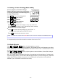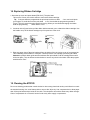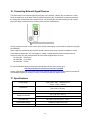
1
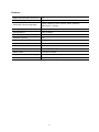
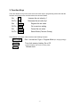
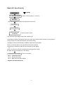
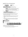
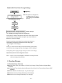
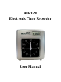
ATR120
Electronic Time Recorder
User Manual
Lithium Battery Caution:
The circuit board on this terminal is populated with a lithium battery to protect data or
programs stored in the Random Access Memory (RAM). Do not, under any circumstances,
attempt to replace the lithium battery in the terminal. Failure to comply may void your
warranty. Battery replacement should be done by qualified personnel wearing the proper eye
protection.
CAUTION: Danger of explosion if the battery is incorrectly replaced. Replace only with the same
or equivalent type recommended by the manufacturer. Discard used batteries according to the
manufacturer’s instruction.
This product utilizes a battery that contains Perchlorate Material.
Perchlorate Material – special handling may apply,
See www.dtsc.ca.gov/hazardouswaste/perchlorate
Table of Contents
1. Before You Start ........................................................1
What’s In the Box ...................................................................... 1
Features: .................................................................................... 2
2. Clock Overview..........................................................3
2.1 LCD Display .......................................................................... 3
2.2 Keypad ................................................................................. 3
2.3 Back Case: Switches............................................................. 3
2.4 Back Case: Power Connector / Bell Connections ................ 3
2.5 Ribbon Life ........................................................................... 4
2.6 Operational Battery Pack..................................................... 4
3. Function Keys............................................................5
4. Menu Trees: Quick Reference ..................................6
Mode b000: Date & Time Settings ............................................ 6
Mode b001: Pay Period / DST Settings ...................................... 7
Mode b002: Alarm Schedule ..................................................... 8
Mode b003: Column In-Out Printing Position ........................... 9
Mode b004: Print Color Change Settings ................................ 10
5. Function Groups ..................................................... 10
5.1 Function Group Overview ................................................. 10
5.2 Function Group Table by Mode ......................................... 11
6. Setting the Time Recorder ...................................... 12
7. Time & Date Settings (Mode b000)......................... 12
7.1 Setting the Year ................................................................. 12
7.2 Setting the Month/Date .................................................... 12
7.3 Setting the Hour/Minute ................................................... 12
7.4 Setting 12 / 24 Hour Time Format ..................................... 12
7.5 Setting the Day Change (Hour and Minute) ...................... 13
7.6 Set Vertical Printing Position (Up/Down) .......................... 13
7.7 Setting the Keyboard Beep ................................................ 13
7.8 Setting the Menu Password .............................................. 13
8. Pay Period Settings (Mode b001) ........................... 14
8.1a Setting a Monthly Pay Period .......................................... 14
8.1b Setting a Weekly Pay Period ............................................ 14
8.1c Setting a Bi-Weekly Pay Period ........................................ 14
8.2 Day of Week Print Format (Language) .............................. 15
8.3 Minute System................................................................... 15
8.4 Setting DST Start (Month & Date) ..................................... 15
8.5 Setting DST Start (Hour & Minute) .................................... 15
8.6 Setting DST End (Month & Date) ....................................... 16
8.7 Setting DST End (Hour & Minute) ...................................... 16
9. Setting Alarm Schedules (Mode b002) .................. 17
10. Setting the IN-OUT Schedule (Mode b003) .......... 18
11. Setting 2-Color Printing (Mode b004) .................. 19
12. Master Resets ........................................................ 19
13. Troubleshooting .................................................... 20
14. Replacing Ribbon Cartridge ................................. 21
15. Cleaning the ATR120 ............................................ 21
16. Connecting External Signal Devices ................... 22
17. Specifications ........................................................ 22
18. Error Codes ........................................................... 23
19. Wall Mounting Instructions .................................. 23
Supplies, Parts & Accessories ................................... 23
Acroprint® Limited Warranty ..................................... 24
Product Registration Card .......................................... 25
1. Before You Start
Please read this manual thoroughly before operating your time clock to avoid damage and to ensure
proper operation.
What’s In the Box
Unpack clock. Inspect clock for any damages that may have occurred during shipment. Check the box
contents for any missing items (see list of contents below). If any damages are found or if any parts are
missing please contact Acroprint Customer Service at (800) 334-7190.
•
ATR120 Time Recorder
•
(2) Clock Cover Keys on Key Ring
•
13vDC 1000mA Switching Power Supply
•
User Manual
•
Extended Service Plan Order Form (06-0343-000)
•
(25) Sample ATR121 Weekly/Bi-Weekly Time Cards
•
Clock Wall Mounting Template
(Also available for download at http://.support.acroprint.com)
•
(3) Mounting Screws
•
(3) Plastic Wall Anchors
Do not attempt to service the ATR120 yourself. Disassembling the clock will void the warranty. Always
follow the instructions in the user guide.
•
Do not place the clock in direct sunlight as this could discolor or deteriorate the plastic.
•
The clock is designed for indoor use in a temperature range of 32-104º F (0-40º C). Keep the
clock away from heat sources such as radiators. Avoid dusty environments or exposure to
chemicals.
•
The clock is not waterproof. It is designed for operational relative Humidity of 10-60%.
•
The clock may be placed upright on a solid surface or mounted to a wall with mounting screws.
Use the enclosed template & screws for wall mounting. Avoid locations where the device will be
susceptible to vibrations and shock, such as a slamming door.
•
The terminal warranty does not cover defects or damages arising from improper installation,
improper storage, abuse, or unauthorized service.
Features:
Display Synchronized to Clock Face
Yes
Display Language
English
Printed Day Format (Languages)
English, Spanish, French, German, Italian, Japanese,
Date, Days 1-7, No Day
Auto Card Feeder
Yes
Printing Method
9-Pin Dot Matrix
Two Color (Red/Black) Printing
Yes
Perpetual Calendar
Yes
Operational Battery Backup
Yes (Optional)
Power Failure Memory Retention
Yes
LCD Hour Display Format
12 or 24 hour
Print Format
Min, 100 , 20 , 10
External Alarm
Connection Available
Programmable Column Changing
Yes
Available Time Cards
Wkly/Bi-Wkly, Monthly
ths
-2-
ths
ths
2. Clock Overview
2.1 LCD Display
Date
DST On
Print Columns
Hour
Minute
SUN MON TUE WED THU FRI
IN1 OUT1 IN2 OUT2 IN3 OUT3
2.2 Keypad
2.3 Back Case: Switches
Run
ON
Prgm
OFF
Reset
Reset Button: restarts clock (same as powering off and back on)
Prgm Switch: Move to “Prgm” to access clock settings.
On/Off Switch: Move to “On” to enable battery backup of clock settings. Note that if the switch is
moved to “Off” and the clock is unplugged for a few minutes some user settings may be lost.
The purpose of the switch is to save battery power for memory backup when the clock is not
being used.
2.4 Back Case: Power Connector / Bell Connections
Bell
Connections
Wire
Releases
Power
Connector
-3-
2.5 Ribbon Life
The ATR122r ribbon (39-0127-002) will typically last 3 months with 50 employees punching 6 times per
day (~18,000 punches). Actual ribbon life will vary based on the number of punches, humidity, temperature
and exposure to air.
2.6 Operational Battery Pack
The ATR120 with Operational Battery Pack (01-0212-002) is available for customers that require backup
power. The Battery Pack (58-0109-001) is a 9 cell NiCad (Nickel Cadmium) battery pack that charges
when the ATR120 is plugged in. In the event of a power failure the clock will instantly switch to battery
power without any interruption in service. The operational battery pack allows for full operation of the clock.
The battery pack is available as an add-on to standard clocks but must be factory installed or installed by a
certified Acroprint dealer.
Battery Pack Specs: (new battery)
Voltage: DC 10.8v
Capacity: 1000mAh
Standby mode: ~40 Hr Reserve Power
Fully charged: The clock has been tested for over 3 Hrs and 6,000 continuous punches.
Note: Actual battery life depends on many factors such as battery age, temperature, discharge history, etc.,
and can vary greatly depending on these factors. The ATR120 should be plugged in for at least 12 hours to
fully charge the battery pack.
Warning:
Batteries may leak, overheat, catch fire or explode if proper safety & handling procedures are not followed:
• DO NOT get batteries wet
• DO NOT place batteries near heat sources
• DO NOT use any power supply other than the original one supplied with the time recorder.
• DO NOT inverse polarity connection
• NEVER throw batteries into fire. Properly dispose of batteries according to local rules and
regulations.
• DO NOT allow anything to short circuit the batteries
• Dropping a battery may damage the battery.
Replace the battery if you suspect any damage.
-4-
3. Function Keys
The In-Out buttons on top of the clock serve as function keys in programming mode. Note that the
functions are printed on the card door above the column numbers.
IN1
= +
OUT1 = IN2
Increase the set value by 1
Decrease the set value by 1
= Enter
Register the set value
OUT2 = Back
Go to previous setting
IN3
Cancel the set value
= Clear
OUT3 = Mode
Select Mode (Function Group)
The switches on the back of the clock have the following functions:
Run / Prgm
On / Off
Run – normal use. Prgm = Program Mode
Turn clock memory battery On or Off
(conserves battery when clock isn’t being used)
Reset
Restart clock
-5-
(for changing settings)
4. Menu Trees: Quick Reference
Mode b000: Date & Time Settings
= [Enter]
Mode: b000
01 - Year
Default: Year of last firmware update
02 – Month / Date
Default = 01 01
03 – Hour / Minute
04 – 12/24 Hr. System
Default = 08 00 am
Default = 12 (controls the Hour format of
both the LCD display and the print format).
05 – Day Change Hr / Min
Default = 12 00 am
06 – Set Up / Dn Print Position
07 – Beep
08 – Set Password
Range: 00-09 (Default = 5)
Increasing value moves the print up
On: 00 01 (Default = on)
Off: 00 02
Default = None (00 00)
Range: 0001 - 9999
-6-
Mode b001: Pay Period / DST Settings
Mode: b001
01 – Pay Period
Type
Set Pay Period
Monthly End Date or
Wkly/Bi-wkly Current Day
02 – Day of Wk
Print Format
03 – Minute System
04 – DST Mo/Date
Start
= [Enter]
01 31 = Monthly
02 01 = Weekly (Default)
03 01 = Bi-Weekly
Monthly (01): 1-31 (Set “31” Mo. End Date)
Weekly (02): 1-7 1=Mon, 2=Tue…7=Sun
Bi-Weekly (02): 1-14
Wk 1: 1=Mon, 2=Tue…7=Sun
Wk 2: 8=Mon, 9=Tue…14=Sun
0 = Date
1 = English (Default)
2 = Spanish
3 = French
4 = German
00 01 = 1/60 (Min)(Default)
00 02 = 1/100 Hour
00 03 = 1/20 Hour
00 04 = 1/10 Hour
Default = 00 00
05 – DST Hr/Min Start
Default = 02 00 am
06 – DST Mo/Date End
Default = 00 00
07 – DST Hr/Min End
5 = Italian
6 = Japanese
7 = Day# 1-7
8 = No Indication
Default = 02 00 am
-7-
Ex: 6:28am
06:28
06.47
06.45
06.40
Mode b002: Alarm Schedule
= [Enter]
Mode: b002
01 – Set Alarm Duration
Default = 00 05 sec (Range = 0 to 60 sec)
Set Alarm #
(Press & hold [Enter] to advance through Alarms 02 thru 25)
Set Alarm Hour
Set Alarm Minute
Set Days that Alarm
will Activate
Default = All Days of Week
“Sun” will flash (if the settings haven’t been adjusted yet)
Press [Enter] to advance through each day of the week (days will flash when selected) or press [Clear] to
accept all days of the week and advance to next Alarm setting.
(Accepting all days will automatically set Both the Internal & External alarm
Press [+] to activate alarm for any days that have been de-selected,
Press [Enter] to activate the alarm (the day will appear on the display)
or
Press [-] to cancel an alarm for the selected day, press [Enter] to cancel
the Alarm (the day will disappear on the display)
Set which Alarm will Sound
00 01:
00 02:
00 03:
Default = 00 03 (Both)
Internal Alarm Only
External Alarm Only
Both Internal & External Alarm
Repeat to set Alarms 02 thru 25
-8-
Mode b003: Column In-Out Printing Position
= [Enter]
Mode: b003
01 – Set Print Column Change
Column Changes 01 thru 24
(Press & hold [Enter] to advance through all Column Changes)
Note: In Run Mode the current print Column
is shown at the bottom of the display
(IN1, Out1, IN2, OUT2, IN3, OUT3)
Set Hour
Set Minute
Set Days that Column Change will Activate
Default = All Days
“Sun” will flash (if the settings haven’t been adjusted yet)
Press [Enter] to advance through each day of the week (days will flash
when selected) or press [Clear] to accept all days of the week and
Advance to next Column change
Press [+] to set column change for any days that have been de-selected,
Press [Enter] to activate a column change (the day will appear on the
display)
or
Press [-] to cancel a column change for the selected day, press [Enter]
to cancel the column change (the day will disappear from the display)
Set Print Column
Single Work Shift Example:
Print Column:
Function:
1
In 1
Start Shift
2
3
Out 1
In 2
Lunch Start Lunch End
4
6
Out 2
In 3
Out 3
End Shift
OT In
OT Out
Repeat steps to set Column changes 01 thru 24
Note: If a manual column change is made the clock will shift back to the
current programmed column within (5) seconds.
-9-
5
Mode b004: Print Color Change Settings
Mode: b004
= [Enter]
Note: all odd# color changes will
set Red printing. All even#
color changes will set Black
printing.
(Press & hold [Enter] to advance through
Color Changes 01 thru 24)
01 – Set Print Color to Red,
Change Time #01
Set Hour
Set Minute
Set Days that Color Change will Activate
Default = All Days
“Sun” will flash (if the settings haven’t been adjusted yet)
Press [Enter] to advance through each day of the week (days will flash
when selected) or press [Clear] to accept all days of the week and
Advance to next Color change
Press [+] to activate color change for any days that have been
de-selected, press [Enter] to activate the color change (the
day will appear on the display)
or
Press [-] to cancel a color change for the selected day, press [Enter]
to cancel the color change (the day will disappear from the display)
Press [Enter] (after cycling through all days) to set the color change
Repeat steps to set Color Changes 01 thru 24
Note:
there is no icon on the display to indicate the current print color
when an employee is punching.
5. Function Groups
5.1 Function Group Overview
b000: Year, Month, Date, Hour, Minute, 12/24 Hr, Day Change, Printing Position, Keyboard Beep,
Password
b001: Pay Period Type: Monthly, Weekly, Bi-weekly; Day of Week Print Format, Minute System, DST
Start/End
b002: Alarm Duration, Set Alarms (02 - 25), Set Alarm Type
b003: Set Print Column Change Schedule (01-24 changes)
b004: Set Print Color Change Schedule (01-24 changes)
- 10 -
5.2 Function Group Table by Mode
Mode b000
Code
01
Function
Setting the Year
02
Setting the Month/Date
03
Setting the Hour/Minute
04
Setting 12 Hr / 24 Hr Time Format
05
Setting the Day Change (Hour/Minute)
06
Adjusting Printing Position (Up/Down)
07
Setting Keyboard Beep (On/Off)
08
Set Password (to access clock menus)
Mode b001
Code
01
Function
Setting Monthly, Weekly or Bi-weekly Pay Period
02
Day of Week Print Format
03
Setting the Minute system
04
Setting DST Start (month & date)
05
Setting DST Start (hour & minute)
06
Setting DST End (month & date)
07
Setting DST End (hour & minute)
Mode b002
Code
01 - 24
Function
Setting the Alarm Duration (0 - 60 sec)
Setting the Alarm (02 - 25)
Setting internal alarm, external alarm or both
Mode b003
Code
01 - 24
Function
Setting the IN-OUT Column printing position (01 - 24)
Mode b004
Code
01 - 24
Function
Setting the Red/Black Color Change Schedule (01 - 24)
- 11 -
6. Setting the Time Recorder
Place clock in program mode: move the program switch on back of clock
from “Run” to “Prgm”.
Press Mode (Out3) to toggle between Program Modes b000, b001,
b002, b003 & b004.
Tip: Pressing & holding Enter will slowly advance through the
programming menus.
7. Time & Date Settings (Mode b000)
Program Mode b000
7.1 Setting the Year
Press Enter to edit program Code 01.
The year flashes on the right of the display.
Press + or – to edit the year.
Press Enter to set the year.
Code
Year
7.2 Setting the Month/Date
Press Enter to edit program Code 02.
Press
+ or – to edit the month.
Code Month
Press Enter to set the month.
Press
+ or – to edit the date.
Press Enter to set the date.
Date
Code
7.3 Setting the Hour/Minute
Press Enter to edit program Code 03.
Press
+ or – to edit the hour.
Code Hour
Press Enter to set the hour.
Press
+ or – to edit the minute.
Press Enter to set the minute.
Minute
Code
7.4 Setting 12 / 24 Hour Time Format
This setting controls the hour format of both the LCD display and print format.
Press Enter to edit program Code 04.
Press
+ or – to edit the time format:
12 Hr (Factory Default)
Code
24 Hr
Press Enter to set the time format.
- 12 -
Hr. Format
7.5 Setting the Day Change (Hour and Minute)
Note: this feature can be used for employees that start their shift on the previous day and end on the next
day
Press Enter to edit program Code 05.
Press
+ or – to edit the hour.
Code Hour
Press Enter to set the Day Change Hour.
Press
+ or – to edit the minute.
Press Enter to set the Day Change Minute.
Code
Minute
7.6 Set Vertical Printing Position (Up/Down)
Press Enter to edit program code 07.
Press
+ or – to edit the printing position (0-9).
Code
Press Enter to set the printing position.
Note: Increasing the value from 00 to 09 moves print up a total of 6mm. Decreasing the value moves the
print down. “5” is the Factory Default.
7.7 Setting the Keyboard Beep
Press Enter to edit program code 08.
Press + or – to set the keyboard beep:
00 01 = Beep On (Factory Default)
00 02 = Beep Off
Press Enter to set the keyboard beep.
Code
7.8 Setting the Menu Password
Note: the menu password prevents unauthorized personnel from accessing the clock menus.
Press Enter to edit program code 09.
Press
+ or – to edit the password.
Note: 00 00 is the Factory Default (no password).
To remove a password simply change the password back to 00 00.
Code
Press Enter to set the password.
Press Mode to advance to the next programming mode (B001). To exit programming mode slide the
switch on the back of the clock to “Run”.
- 13 -
8. Pay Period Settings (Mode b001)
Pay
Period
Code
Program Mode b001
Pay Period Type
01
Monthly Pay Period
02
Weekly Pay Period (Factory Default)
03
Bi-Weekly Pay Period
8.1a Setting a Monthly Pay Period
Press Enter to enter program Code 01.
Press
+ or – to change Pay Period type to “01”
Code
Mo. P.Period
End Day
Pay Period
Type
Press Enter to set Monthly Pay Period.
The Monthly Pay Period End Day (31) will begin flashing.
This is the correct end day for the ATR121 Monthly Time Card (do not change this value).
8.1b Setting a Weekly Pay Period
Press Enter to enter program code 01.
Press
+ or – to change the Pay Period to “02”
Press Enter to set the Pay Period type to Weekly.
Press
+ or – to select the current day of week:
Code
Current
Day of Wk
P.Period Type
01=Mon, 02=Tue, 03=Wed, 04=Thu, 05=Fri, 06=Sat, 07=Sun
Press Enter to set the current day of the week.
Note: as the day changes this value will change to reflect the current day of the week.
8.1c Setting a Bi-Weekly Pay Period
Press Enter to enter program code 01.
Press
+ or – to change the Pay Period to “03”
Press Enter to set the Pay Period type to Bi-weekly.
Press
+ or – to select the current day of the week:
Current Day
of Week
Pay Period Type
Code
Wk 1: 01=Mon, 02=Tue, 03=Wed, 04=Thu, 05=Fri, 06=Sat, 07=Sun
Wk 2: 08=Mon, 09=Tue, 10=Wed, 11=Thu, 12=Fri, 13=Sat, 14=Sun
Note: Wk 1 days will print on the top half of the time card. Wk 2 days will print on the bottom half of the
time card.
Press Enter to set the current day of the week.
Note: as the day changes this value will change to reflect the current day of the week.
- 14 -
8.2 Day of Week Print Format (Language)
Press Enter to enter program code 02.
Press
+ or – to edit the Day of Wk print format.
Code
Press Enter to set the Day of Wk print format.
Code
Fmt
00 01
English
00 02
Spanish
00 03
French
00 04
German
00 05
Italian
00 06
Japanese
Day of Week
Print Format
00 07
00 08
Day# 1-7
No Day
8.3 Minute System
Press Enter to enter program code 03.
Press
+ or – to edit the Minute System format.
00 01 = 1/60 Hr (Minutes = Factory Default)
th
00 02 = 1/100 Hr
th
00 03 = 1/20 Hr
th
00 04 = 1/10 Hr
Code
Minute System
Press Enter to set the Minute System format.
Conversion Chart:
8.4 Setting DST Start (Month & Date)
Press Enter to enter program code 04.
Press
+ or – to edit the DST Start Month.
Code Starting Mo.
Press Enter to set the DST Start Month.
Press
+ or – to edit the DST Start Date.
Press Enter set the DST Start Date.
Once the Start Date is set the day corresponding to the date will show at
the top of the display.
Code
Starting
Date
8.5 Setting DST Start (Hour & Minute)
Press
Enter
to enter program code 05.
Press
+ or – to edit the DST Start Hour.
Press
Enter
Press
+ or – to edit the DST Start Minute.
Press
Enter
Code Starting Hr.
to set the DST Start Hour.
Code
to set the DST Start Minute.
- 15 -
Starting
Minute
8.6 Setting DST End (Month & Date)
Press
Enter
to enter program code 06.
Press
+
–
Press
Enter
Press
+ or – to edit the DST End Date.
or
to edit the DST End Month.
Code Ending Mo.
to set the DST End Month.
Press Enter to set the DST End Date.
Once the End Date is set the day corresponding
to the date will show at the top of the display.
Code
Ending
Date
8.7 Setting DST End (Hour & Minute)
Press
Enter
to enter program code 07.
Press
+ or – to edit the DST End Hour.
Press
Enter
Press
+ or – to edit the DST End Minute.
Press
Enter
Code Ending Hr.
to set the DST End Hour.
to set the DST End Minute.
Code
Ending
Minute
Press Mode to advance to the next programming mode (B002). To exit programming mode slide the
switch on the back of the clock to “Run”.
- 16 -
9. Setting Alarm Schedules (Mode b002)
You may set up to 25 Alarms (01 thru 25) to signal shift start/end,
lunch start/end, OT start/end, etc.
Program Mode b002
Press Enter to enter program code 00.
Press
+ or – to edit the Alarm Duration (0-60 sec, Default = 5 sec).
Press Enter to select the Alarm# (press & hold Enter to advance through
Code
Alarm Duration
Alarms 01-25. It takes 3 sec. to cycle through each alarm).
Press
+ or – button to edit the Hour.
SUN MON TUE WED THU FRI SAT
Press Enter to set the Hour.
Press
+ or – button to edit the Minute.
Alarm# Hour
Press Enter to set the Minute.
Press
Clear
Min
to set the alarm to go off every day of the week (by default the alarm is set for all week
days & the weekend)
Note: Pressing Clear
next alarm#.
or
will set the alarm for all days, automatically sets both alarm types and goes to
Press
week).
– to cancel selected (flashing) day (press “Enter” to continue advancing through each day of the
Press
+
Press
+ or – to edit the Alarm Type.
to add a day that has been deleted.
00 01 = Internal Alarm
00 02 = External Alarm
00 03 = Internal + External Alarm
Press Enter to set the Alarm Type.
Press Mode to advance to the next programming mode (B003). To exit programming mode slide the
switch on the back of the clock to “Run”.
Note: see Section #17 “Connecting External Signal Devices” for more information on how to connect bells
and horns to the ATR120.
- 17 -
10. Setting the IN-OUT Schedule (Mode b003)
Program Mode b003
You can program up to 24 Column Changes to set
the print column for in/out times for shifts, breaks,
lunch, overtime, etc.
Note: the selected print column is displayed at the
bottom of the display (IN1, OUT1, IN2, OUT2, IN3, OUT3). To skip a print column in the schedule simply
leave the time for that Column Change# blank.
Press Enter to enter Column Change# 01.
SUN MON TUE WED THU FRI SAT
(or press & hold Enter to slowly advance through
IN1
Column Changes 01-25.)
Press
+
or – to edit the Hour.
Press Enter to set the Hour.
Press
Selected
Print
Column
Hour
Column
Change#
Min
+ or – to edit the Minute.
Press Enter
to set the Minute.
Press Clear to set the column change for every day of the week and advance to the next column
change#. (by default the column change is set for all week days & the weekend)
or
Press
week).
– to cancel selected (flashing) day (press “Enter” to continue advancing through each day of the
Press
+
to add a day that has been deleted.
Press Mode to advance to the next programming mode (B004). To exit programming mode slide the
switch on the back of the clock to “Run”.
- 18 -
11. Setting 2-Color Printing (Mode b004)
You can program up to 24 Color Changes.
Example: the clock can be set to print punches
in red if they fall outside normal working hours,
ie, early or late punches.
Program Mode b004
Press Enter to enter Color Change# 01.
Press
SUN MON TUE WED THU FRI SAT
+ or – to edit the Hour.
Press Enter to set the Hour.
Press
+ or – to edit the Minute.
Press Enter
Code Hour
Min
to set the Minute.
Press Clear to set the color change for every day of the week
(by default the color change is set for all week days & the weekend)
and advance to the next color change#.
or
Press – to cancel selected (flashing) day (press “Enter” to
continue advancing through each day of the week).
Press
+
to add a day that has been deleted.
Note:
all odd# color changes will set Red printing. All even# color changes will set Black printing.
To exit programming mode slide the switch on the back of the clock to “Run”.
12. Master Resets
Press
+
&
Clear
& Mode
(Keys 1, 5, 6) all together to reset the
clock settings back to their original (factory) defaults. This will not reset the Clock Password or any Alarm,
Column Shift Change or Color Change schedules. See Section 4 “Menu Trees - Quick Reference” to view
the factory defaults for various settings.
Press – & Clear & Mode
Color Change schedules.
(Keys 2, 5, 6) all together to remove all Alarm, Column Shift Change or
Note: the “Reset” button on the back of the clock will re-start the clock (the equivalent of unplugging the
clock and plugging it back in). This is useful if the clock program locks up. It will not change any of the clock
settings back to factory defaults as long as the coin cell battery for memory backup is still good and
switched on (the On/Off switch on the back of the clock).
- 19 -
13. Troubleshooting
Press the
RESET
Trouble
The date is
incorrect
button on the back of the clock to re-start the clock if becomes “locked up”.
Causes
Corrective Measures
Date set incorrectly
Set current date
The clock
is slow/fast
1. Time set incorrectly.
2. Power failure
1. Set it correctly.
2. Reset the machine.
The time clock
does not accept
time card
1. Power failure
2. The time card is damaged
3. The power cord is
disconnected.
4. Cards were inserted or pulled
out by force.
1. Wait until power supply is restored
2. Change a new time card
3. Insert the power plug firmly into the power
outlet.
4. Press “Reset” or unplug & plug back in.
1. Day Change set incorrectly.
1. Set Day Change correctly.
2. Pay Period Type not
set correctly for card type.
2. Make sure to insert the
card in the card slot and
remove it properly.
1. The ribbon cartridge is not
inserted correctly.
2. The ribbon is dried out.
3. The ribbon is stuck.
1.
The printing
position is wrong
Light printing
Ink Smudges
Ribbon inserted behind print
shield.
Settings Change
Low battery backup to
clock memory.
Insert cartridge correctly.
2. Change ribbon cartridge.
3. Rotate ribbon knob. Replace cartridge if ribbon
doesn’t advance.
Re-install cartridge with
ribbon inserted between ribbon guide and print shield.
Replace Coin Cell battery.
Forgotten
Password
Contact Acroprint Customer Support at (800) 334-7190
for assistance in password recovery.
- 20 -
14. Replacing Ribbon Cartridge
1. Open the top cover and press button [PM Out 2]. The print head
will move to Column 4 to make it easier to remove the ribbon cartridge.
Tip: if column shifts are programmed the print head could move after
3 sec. and could pinch
your fingers. To avoid this move the print head
to Col. 4 and slide the programming switch to
“Prgm”. This will prevent the print head from moving. When you are finished changing the ribbon
slide the programming
switch back to “Run”.
2. As shown in the figures below, pull the ribbon holders towards you to unlatch the ribbon cartridge. Use
the handle on top of the ribbon cartridge to pull it up and out of the clock.
3. Blow any paper dust off the print head and from the inside of the clock using a can of compressed air.
This could help prevent ribbon or card jams. Carefully insert a new cartridge, positioning the ribbon
between the plastic ribbon guide and the stainless steel print shield. Push the cartridge down until it
clicks into place. Turn the ribbon knob clockwise to remove any slack in the ribbon. Slide the program
switch back to “Run”.
15. Cleaning the ATR120
Do not use cleaning products that contain alcohol or other strong chemicals as they could discolor or crack
the terminal housing. Use a soft damp cloth to remove dirt. Wipe dry. Use compressed air to blow paper
dust off the print head and the inside of the clock. This should be done with at least every ribbon change.
Cans of compressed air or “Dusters” can be found at any office supply or superstores.
- 21 -
16. Connecting External Signal Devices
The connections for an external signal device (bells, horns, buzzers, chimes, etc) are made via a 2-wire
Green terminal block on the back of the clock above the power jack. Connections are made by pressing
the orange wire release tabs below each wire hole, fully inserting the wire and releasing the clip. Gently
pull on the wires to make sure they are firmly secured in the terminal block.
A relay is required in order to use a bell or horn. Please call Acroprint or your Dealer to order the relay (PN
01-0230-000).
When a signal is activated by the clock the internal contacts of the relay close and complete the circuit.
These internal contacts are "dry" and supply no voltage. Voltage applied to these contacts must not
exceed 30 volts. The relay then activates the 120v external signal device such as:
65-0103-000
65-0104-000
65-0105-000
"Grille Horn"
"4-1/4" Bell"
"8" Bell"
For more information about connecting an external signal device using a relay go to:
http://www.acroprint.com/resources/user-manuals
Locate “ATR120/ATR120r Time Clock” in the list of products, and click on the product name to reveal a list
of all available support documents, including “Connecting an External Signal Device.”
17. Specifications
Power Supply
Input: 100v / 240v, 50/60 Hz, 0.6A
Output: 13vDC, 1000mA
Dimensions
Approx: 9 x 8 x 5 (H x W x D)
(230 x 205 x 128 mm)
Weight
3.35 Lbs (1.524 Kgs)
32º - 104º F (0 – 40º C)
Usage Environment
10 - 60% Relative Humidity
Time Card Size
86 x 185 x 0.35 mm ( W x L x Thk )
Circuit Board Battery
CR2032 3v Lithium Coin Cell
Ribbon Cartridge
Red / Black
- 22 -
18. Error Codes
If an Error code is displayed on the LCD contact your dealer or Acroprint for assistance:
Err1--Wrong Position (Up & Down)
Err2--Wrong Position (Left & Right)
Err3--Internal Memory Error (usually indicates power failure)
Err4--Wrong Password
19. Wall Mounting Instructions
The ATR120 can be placed on a table or desk and it can also be mounted to a wall. A mounting
template is included with the documents for the ATR120. If you misplace the template you can
download it at:
http://www.acroprint.com/resources/user-manuals
Locate “ATR120/ATR120r Time Clock” in the list of products and click on the product name to
reveal a list of all available support documents, including the wall mounting template.
Follow the instructions on the template to mount the clock.
Supplies, Parts & Accessories
Part#
Description
01-0230-000
24 Volt Switching Relay Kit
01-0212-000
ATR120 Electronic Time Recorder
01-0212-002
ATR120 Time Recorder w/Battery Backup
06-0314-002
ATR120 User Manual (available on web)
06-0413-000
Mounting Template (available on web)
09-9110-000
ATR121 Wkly/Bi-Wkly Time Card (pack of 250)
09-9113-000
ATR121 Monthly Time Card (pack of 250)
39-0127-002
ATR122r Replacement Ribbon
45-0180-000
Key Set, ES700/900/1000; ATR120
56-0137-000
13v DC 0.5A Switching Power Supply
58-0109-001
ATR120 Operational Battery Pack
64-0103-000
Grille Horn, 120vAC 50/60Hz
64-0104-000
4-1/4" Bell, 120vAC 50/60Hz
64-0105-000
8” Bell, 120vAC 50/60Hz
81-0120-000
ATR120R Expanding Card Rack
An updated list of accessories with pricing can be found on the
web at:
www.acroprint.com
- 23 -
Acroprint® Limited Warranty
Should you have any questions concerning your warranty information or supplies, please contact the dealer
or store where you purchased the equipment.
This product is guaranteed to the original purchaser for a period of two (2) years from original purchase date
against defective materials and workmanship when used under normal operating conditions. You must
contact us to obtain a Warranty Return Authorization (WRA) prior to shipping the product to us.The repair or
replacement of any defective component or part and any necessary adjustments will be made free of
charge provided that the machine is shipped prepaid to the factory service center shown below, securely
packaged and shipped in the original shipping container. This warranty applies to Acroprint products
purchased and retained in the U.S.A. The guarantee is not applicable if the device has been subject to
misuse, abuse, negligence, accidents, power surges and lightning. The guarantee is not applicable if the
serial number has been altered, defaced or removed or if the device has been tampered with or taken apart
by anyone other than authorized service personnel.
Please return the warranty card on the following page to Acroprint to register your
product. Or, if you would like to register online go to www.acroprint.com/warranty. For your
reference, fill out the information below and keep it in a safe place.
ATR120r
Model Number __________________________________
Serial Number ___________________________________
Date Purchased _________________________________
Purchased From _________________________________
Purchase Location ________________________________
Store Telephone Number __________________________
Acroprint Time Recorder
5640 Departure Drive
Raleigh, NC 27616-1841
- 24 -
Product Registration Card
Model No._______________________ Serial No.________________________
First Name______________________
Last Name_______________________
Title_____________________________________________________________
Company Name ___________________________________________________
Address__________________________________________________________
City_______________________
State________
Zip_______________
Daytime Phone with Area Code_____________________________
Purchased From___________________
Purchase Date______________
So that we may serve you better, please indicate your primary business activity.
(01) Manufacturing
(02) Wholesale
(03) Retail
(04)
(05)
(06)
Government
University / School
Other ________________
(14)
(15)
(16)
50 - 75
76 - 100
100+
(24)
(25)
(26)
$500,000 - $1,000,000
$1 million - $5 million
$5 million and over
Number of Employees Using Product
(11) 1 – 10
(12) 11 - 25
(13) 26 - 49
Annual Sales in Dollars
(21)
(22)
(23)
Under $100,000
$100,000 - $250,000
$250,000 - $500,000
Comments: ___________________________________________________________
_____________________________________________________________________
- 25 -
06-0314-002 Rev. E