1
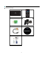
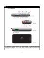
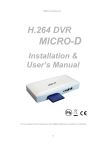
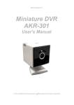
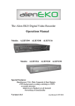
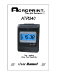
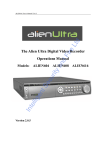
Vista MiniD-400
Installation & User Manual
1
Before You Begin
Read these instructions before installing or operating this product.
Note: This installation should be made by a qualified service person and should conform to local codes.
This manual provides installation and operation information. To use this document, you must have the following minimum qualifications:
y A basic knowledge of CCTV systems and components
y A basic knowledge of electrical wiring and low-voltage electrical connections
Intended use
Only use this product for its designated purpose; refer to the product specification and user documentation.
Customer Support
For assistance in installing, operating, maintaining and troubleshooting this product refer to this document and any other documentation provided. If you still have
questions, please contact Norbain Technical Support and Sales:
210 Wharfedale Road
Winnersh Triangle, Wokingham, Berks
RG41 5TP
0118-912-5000
Note: You should be at the equipment and ready with details before calling Technical Support.
Conventions Used in this Manual
Boldface or button icons highlight command entries.
equipment is not handled properly:
The following WARNING, CAUTION and Note statements identify potential hazards that can occur if the
* WARNING:
Improper use of this equipment can cause severe bodily injury or equipment damage.
** Caution:
Improper use of this equipment can cause equipment damage.
Note:
Notes contain important information about a product or procedure.
RoHS Announcement
All lead-free products offered by the company comply with the requirements of the European law on the Restriction of Hazardous Substances (RoHS)
directive, which means our manufacture processes and products are strictly “lead-free” and without the hazardous substances cited in the directive.
The crossed-out wheeled bin mark symbolizes that within the European Union the product must be collected separately at the product end-of-life.
applies to your product and any peripherals marked with this symbol. Do not dispose of these products as unsorted municipal waste.
This
CE Mark
This apparatus is manufactured to comply with the radio interference. The company does not warrant that this manual will be uninterrupted
or error-free. We reserve the right to revise or remove any content in this manual at any time.
* This symbol indicates electrical warnings and cautions.
** This symbol indicates general warnings and cautions.
NORBAIN SD LTD reserves the right to make changes to the product and specification of the product from time to time without prior notice.
WARNINGS AND CAUTIONS
To reduce the risk of fire or electric shock, do not insert any metallic objects through the ventilation grills or other openings on the
equipment.
CAUTION
24VAC Type Model: Use Certified/Listed Class 2 power supply transformer only.
2
PRECAUTIONS
The height and linearity controls located at the rear panel are for adjus
tments by qualifies personnel only.
Safety----------------------------------------Should any liquid or solid object fall into the MiniD400, unplug the un
it and have it checked by a qualified person before operating again.
Installation---------------------------------------Do not install the unit in extremely hot or humid environments or plac
es exposed to excessive dust or mechanical vibrations.
Unplug the unit from the wall outlet if it is not going to be used for
several days. To disconnect the cord,
pull it out by the plug, never
by the cord itself.
Allow adequate air circulation to prevent internal heat build-up.
t place the unit on surfaces (rugs, blankets, etc.)
Cleaning------------------------------------------Clean the unit with a slightly damp soft cloth. Use a mild household
detergent. Never use strong solvents such as thinner or benzene as the
y might damage the finish of the unit.
Do no
3
TABLE OF CONTENTS
Chapter 1: Packing Contents
CONTENTS IN THE PACKAGE
6
Chapter 2: Getting To Know Your MiniD400
MiniD400
7
Chapter 3: Remote control
REMOTE CONTROL PANEL
9
Chapter 4: Getting Started
OVERVIEW OF SET UP PROCEDURES
11
Chapter 5: Hardware Installation
SD MEMORY INSTALLATION
12
CONNECTING MiniD400 TO YOUR TV SET OR MONITOR
13
ALARM INSTALLATION
14
Chapter 6: OSD MODE
1. ACCESS TO OSD MENU
15
2. MAIN MENU
15
3. SYSTEM SETUP
3.1 TIME SET > DAY LIGHT SAVING
3.2 LANGUAGE SETUP
3.3 VIDEO OUTPUT
3.4 BRIGHTNESS:
16
4. VIDEO SETUP
4.1 RESOLUTION
4.2 VIDEO QUALITY
4.3 FRAME RATE
4.4 PRE RECORDING TIME
4.5 POST RECORDING TIME
4.6 AUDIO RECORDING
4.7 DISK OVERWRITE
17
4
5. EVENT SETUP
5.1 ALARM SETUP
5.1.1 ALARM INPUT
5.1.2 INPUT TYPE
5.1.3 ALARM OUTPUT
19
5.2 MOTION DETECTION
5.2.1 SENSITIVIITY
5.3 SCHEDULE SETUP
20
6. SUB MENU
6.1 PASSWORD CHANGE
6.2 FILE INDEX RENEW
Chapter 7: SCREEN MODE
1. LIVE SCREEN MODE
1.1 SCREEN MESSAGE
1.2 SCREEN ICON
21
2. SEARCH LIST
2.1 SEARCH FACTOR
22
Appendix:
TECHNICAL SPECIFICATIONS
RECORDING TIME TABLE
24
26
5
Chapter 1: Packing Contents
▶ Contents in the package
MiniD400 Main Unit
Remote Controller
Terminal Block
12V Power Supply
AV-IN / AV-OUT Connector
Installation CD
Quick Guide
6
Chapter 2: Getting To Know Your MiniD-400
⑧
⑨
⑩
①
This chapter briefly describes the functions of each button on MiniD400. The buttons are used to operate
the basic functions of MiniD400, such as recording, playback, fast-forward, reverse play and etc. For more
details on the set-up and operation of MiniD400, refer to Chapter 6, MiniD400 MENU.
7
1
Sensor-in / Alarm-out
The sensor terminal block is used to connect a sensor such as PIR to the MiniD400. If you add motion
sensor devices to your MiniD400, the video recording can be triggered by event.
The alarm output terminal is used to install a single alarm device.
2
SD Memory Slot
Insert SD Card into the slot for storing data.
3
Recording LED
This light indicates while MiniD400 is on recording mode.
4
Status LED
This light blinks when events occur or there is any error.
5
Power LED
This light indicates the MiniD400 is powered up.
6
Remote control Receiver
When controlling MiniD400 by remote control, be sure to point at the receiver.
7
Reset
Press the reset button if you want to return setting values to the default.
8
AV-IN
Connect AV-IN connector
9
AV-OUT
Connect AV-OUT connector
10
Power
Connect 12V power supply in the package.
8
Chapter 3: Remote control
Start MiniD400 recording or stops recording.
Turn the SD power off when pressing the REC button for 3 seconds.
(Recording can resume after 20 seconds)
Enter OSD menu.
On OSD menu, go to the upper menu.
1
REC
2
MENU
3
UP/
DOWN
On OSD menu, chooses menu fields and change values.
On search mode, play the previous or next recorded file.
4
LEFT/
RIGHT
REW: Fast Rewind (X2-X4-X8-X16)
FF: Fast Forward (X2-X4-X8-X16)
5
REW
REW: Fast Rewind (X2-X4-X8-X16)
6
FF
FF: Fast Forward (X2-X4-X8-X16)
7
PLAY
Playback at X1
8
STOP
Stop recording or playback. On playback mode, go back to the first frame.
9
PAUSE
Pause playback or resume playback.
10
MUTE
Remove audio.
11
ENT
On playback mode, playback at X1.
On OSD menu, enter values.
12
SEARCH
Enter Search menu.
On search menu, move to upper search menu.
13
MODE
Switch between playback mode and live view mode.
9
Remote Control Functions in LIVE MODE and PLABACK MODE
Function
LIVE
PLAY BACK
Stand-by
Recording
Stand-by
Play
Menu
RECORD
O
O
X
X
X
MENU
O
X
O
O
O
SEARCH
O
X
O
O
X
MODE
O
X
O
O
O
UP
X
X
O
O
O
DOWN
X
X
O
O
O
REW
X
X
X
O
O
FF
X
X
X
O
O
ENTENT
X
X
O
O
O
REW
X
X
X
O
O
FF
X
X
X
O
O
PLAY
X
X
O
O
O
STOP
X
X
X
O
X
PAUSE
X
X
X
O
X
MUTE
X
X
X
O
X
10
Remark
O: Available
X: N/A
Chapter 4: Getting Started
OVERVIEW ON SET-UP PROCEDURES
Below is an overview of the MiniD400 installation procedures, (A detailed explanation is found in
Chapter 5 - Hardware Installation.)
(1) Insert a SD MEMORY.
(2) Connect MIiniD400 to a TV set or monitor.
(3) Connect camera to MiniD400.
(4) Connect optional accessories (sensors or alarm).
(6) Connect the power.
(7) Turn the power on.
(8) Start TV Monitoring and recording.
General Operating Advice:
● Make sure that a SD Memory is inserted and a camera is properly connected.
(See Chapter 5 -Hardware Installation)
● The SD Memory Format setting must be set (Refer to Chapter 5 – SD Memory Installation for more
information.) Otherwise, MiniD400 may not recognize the SD Memory.
● The firmware used in MiniD400 is compatible with your computer’s operating system (i.e. Windows).
Therefore, you can take the SD memory card from this MiniD400 and install it in your computer to view
recorded video. (Refer to the PC Viewer manual.)
● MiniD400 offers you the flexibility to choose a recording frame rate (maximum rate: 25 frames per second).
A faster frame rate provides more natural video images in recorded video files. However, it requires more SD
Memory storage. You may reduce the frame rate (minimum rate: 1 frame per second) to fit longer recording
sessions in consideration of your SD card capacity.
● If a camera is normally connected to MiniD400 it enters the default operational state: VIEW mode. In this
mode, MiniD400 does not record nor play the recorded stream. It just shows the Live images from camera
connected to MINID400
● The default recording value for the MiniD400 is set at 25 frames per second with normal video quality.
If you use 1GB SD Memory, MiniD400 can record approximately for 2 hours in a row.
● There is an exception to entering the VIEW mode at start up. If the power is turned off while MiniD400 is
performing emergency recording (i.e. a power failure), it will automatically enter recording mode when the
MiniD400 reboots.
Refer to Chapter 5 - Hardware Installation for more information on installation procedures.
11
Chapter 5: Hardware Installation
SD MEMORY INSTALLATION
① Format SD Memory
Insert SD memory into SD card slot on your PC and format it
in FAT32.
※ In case there is no card slot on your PC, use an external
SD card reader.
② Insert SD Memory into SD slot
on MIiniD400
After formatting, take SD Memory from your PC and insert it
into the MiniD400’s SD slot.
③ Backup recorded files in SD Memory
When SD Memory storage is full, the recorded files can be
backed up in your PC. Insert SD card in your PC and move
the files from the SD card to the HDD of our PC. You can
also check each recorded file through MiniD Player.
※ Vista recommends SanDisk SD cards; these have been tested with MiniD400. Vista does not guarantee
compatibility with other makes.
The SD card brands that Vista can recommend are as follows;
- SanDisk
- SDHC: Sandisk 8GB
Attention
Do not take out the SD card or turn off MiniD400 while it is in record mode. It may damage SD card.
When in record mode, turn off SD power by first pressing recording button for 3 seconds and then take
the SD card out.
12
CONNECTING MiniD400 TO YOUR TV SET OR MONITOR
①
Video Input/Output Connection (For TV / monitor screen display)
To display images from the MiniD400, connect the video output signal to your monitor. Any Television
with a VIDEO INPUT terminal is suitable for displaying the images. The diagram above shows the video
signal connections.
Connect the camera to VIDEO-IN terminal of AV-IN connector; connect the monitor to VIDEO OUT
terminal of AV-OUT connector.
Note: The RCA cable required for this connection is not supplied with the MiniD400.
②
Audio Input / Output Connection (For TV / monitor speaker)
Connect the microphone to AUDIO-IN terminal of AV-IN
connector; connect the speaker to AUDIO OUT terminal of
AV-OUT connector.
Note: The RCA cable required for this connection is
not supplied with the MiniD400.
13
ALARM INSTALLATION
The MiniD400 has an internal switch for sounding an alarm. When a sensor is triggered, the internal
alarm is also activated.
There are two steps to install an alarm.
1. Connect the alarm cable to the alarm switch terminal.
2. Connect the alarm power cables to the appropriate power source.
Refer to the diagram below for information on how to connect an alarm to your MiniD400.
Note: Contact an authorized dealer
for information about buying the
appropriate alarm device for your
needs and for information concerning
proper installation procedures.
14
Chapter 6: OSD MODE
1. ACCESS TO OSD MENU
MiniD400
1.x
****
Press ‘MENU’ button on remote control to access to MiniD400 OSD menu.
Please refer to ‘Chapter 3: Remote control’ about how to use remote control buttons.
The default Password is ‘0000’. The password can be changed on ‘[SUB MENU]Æ[PASSWORD CHANGE]’.
In order to select cameras for recording, set recoding quality, schedule recording times and to set other
operation parameters, you will need to access the MiniD400 menu.
Numerals can be selected by pushing up/down button on remote control.
2. MAIN MENU
No
In the main menu, the ‘indicator ‘>’ will be shown on the left of each menu.
Press ‘UP/DOWN’ button on remote control to select a desired menu. When ‘>’ is indicated on the desired menu,
press ‘ENTER’ button to enter the menu.
15
3. SYSTEM SETUP
Off
English
PAL
HIGH
Configure current time and ‘DAY LIGHT SAVING’ option. On setting the current time, the field order should be
as follows;
2004/02/17 = year / month / day 19:44:32 = hour /minute / second
3.1 TIME SET > DAY LIGHT SAVING
SELECT ‘ON’, when you want to use day light saving time. You can setup a time period when the day light
saving is applied.
3.2 LANGUAGE SETUP
English, French, Dutch, German, Spanish
3.3 VIDEO OUTPUT
Not selectable. Display NTSC or PAL according to unit’s CCD type.
3.4 BRIGHTNESS:
Select brightness value among low, normal and high.
16
4. VIDEO SETUP
4CIF
HIGH
25
HIGH
YES
NO
OFF
30 MIN
4.1 RESOLUTION
Select video resolution (4CIF / 2CIF / CIF)
VIDEO INPUT (LIVE VIEW) Resolution - PAL
HIGH
4CIF
704x576 / 25fps
2CIF
704x288 / 25fps
CIF
352x288 / 25fps
VIDEO INPUT (LIVE VIEW) Resolution - NTSC
NORMAL
704x576 / 25fps
704x288 / 25fps
352x288 / 25fps
HIGH
4CIF
2CIF
CIF
704x480 / 30fps
704x240 / 30fps
352x240 / 30fps
NORMAL
704x480 / 30fps
704x240 / 30fps
352x240 / 30fps
LOW
704x576 / 25fps
704x288 / 25fps
352x288 / 25fps
LOW
704x480 / 30fps
704x240 / 30fps
352x240 / 30fps
PLAY VIEW Resolution - PAL
4CIF
2CIF
CIF
HIGH
NORMAL
LOW
704x576
704x576
704x576
704x576
704x576
704x576
704x576
704x576
704x576
PLAY VIEW Resolution - NTSC
4CIF
2CIF
CIF
HIGH
NORMAL
LOW
704x480
704x480
704x480
704x480
704x480
704x480
704x480
704x480
704x480
17
4.2 VIDEO QUALITY
LEVEL (HIGH / NORMAL / LOW): Select desired video level from ‘LOW’ to ‘HIGH’.
MODE
HIGH
NORMAL
LOW
QUALITY(4CIF)
1500kbps
1000kbps
500kbps
QUALITY(2CIF)
1200kbps
800kbps
400kbps
QUALITY(CIF)
1000kbps
600kbps
300kbps
4.3 FRAME RATE
PAL: Selectable among 25, 12, 8, 6, 3, 1
NTSC: Selectable among 30, 15, 10, 6, 3, 1
4.4 PRE RECORDING TIME
HIGH
MODE
NORMAL
LOW
Bit Rate
Pre Recording
Bit Rate
Pre Recording
Bit Rate
Pre Recording
(kbps)
Time
(kbps)
Time
(kbps)
Time
4CIF
1500
10sec
1000
20sec
500
30 sec
2CIF
1200
15 sec
800
25 sec
400
35 sec
CIF
1000
20 sec
600
30 sec
300
40 sec
4.5 POST RECORDING TIME
Post-recording time means the recording time between the beginning and end of an event.
(Min. 5 sec)
4.6 AUDIO RECORDING:
Audio function can be turned OFF or ON in the menu.
4.7 DISK OVERWRITE
If overwrite is set to ON, the MiniD400 will continue recording while automatically overwriting the oldest
recorded files when SD memory storage capacity is full. Set to OFF, the recording will stop when the SD
Memory is full.
4.7.1. DISK FULL WARNING:
Select ‘ON’ if you want to display ‘DISK FULL WARNING’ when the SD card is full.
4.7.2. REMAINING TIME: This shows remaining time for further recording.
18
5. EVENT SETUP
ON
N.O.
ON
ON
LOW
TIME
1. OFF
2. OFF
3. OFF
4. OFF
5.1 ALARM SETUP
5.1.1 ALARM INPUT (ON / OFF): Select ‘ON’ if you want to use alarm input device.
5.1.2 INPUT TYPE: Select alarm input type between ‘Normally Open’ and ‘Normally Close’
NC: NORMAL CLOSE
NO: NORMAL OPEN
5.1.3 ALARM OUTPUT:
ALARM INPUT
ALARM OUTPUT
Normally Open
Normally Open
Alarm input type is Normal Open.
The device connected to alarm output is in ‘OFF ‘status
and turns ON when events occur.
Normally Open
Normally Closed
Alarm input type is Normal Open.
The device connected to alarm output is in ‘ON ‘status
and turns OFF when events occur.
Normally Closed
Normally Open
Alarm input type is Normal Close.
The device connected to alarm output is in ‘OFF ‘status
and turns ON when events occur.
Normally Closed
Normally Closed
Alarm input type is Normal Close.
The device connected to alarm output is in ‘ON ‘status
and turns OFF when events occur.
Note: In ‘Normal Close’ mode, if an intruder cuts the cable line that connects the sensor to the MINID-400,
sensor recording starts automatically. In ‘Normal Open’ mode, if an intruder cuts the cable line that connects the
sensor to the MiniD-400, the sensor recording will not start at.
19
5.2 MOTION DETECTION
5.2.1 SENSITIVIITY (LOW / NORMAL / HIGH): You can select the motion detection’s sensitivity.
Set to HIGH for greater sensitivity to small movements.
5.3 SCHEDULE SETUP
Make schedule for the recording time. Up to 4 schedules can be set.
5.3.1 TIME: Start to record when scheduled recording time is up.
5.3.2 TIME & EVENT: to record when motion is detected or an alarm occurs within the scheduled period.
6. SUB MENU
6.1 PASSWORD CHANGE
The Factory Default Password is 0000.
To enter this number, press the UP/DOWN
button on the remote control. Once you
input the current password, set a new four
digit password using the buttons UP, REW,
DOWN, FF on the remote control. Then,
confirm your new password by entering the
number again.
Yes
No
112 MB
480MB
6.2 FILE INDEX RENEW
The index file is automatically generated
and stored in the SD card when inserted
into MiniD400. If the index file does not
match the files actually stored in the SD
card, users can synchronize the index file
list and the actual file list.
While
synchronizing, the process percentage is
displayed; on completion the value returns
to ‘NO’.
Yes
No
112 MB
480MB
20
Chapter 7: SCREEN MODE
1. LIVE SCREEN MODE
When in live screen mode, ‘time & date’ information, screen icons and messages are shown on the screen.
1.1. SCREEN MESSAGE
Message
Description
INITIALIZING…
Displays when the MINID400 is first booted.
WAIT…
Displays when playback and live modes are switched or when the screen
mode and OSD menu are switched.
FILE NOT FOUND
Displays when there is no recorded files in the SD or no search result on
search mode.
SD CARD ERROR
Displays when the SD card is physically damaged or recorded files in the
SD CARD are damaged.
NO SIGNAL
Displays when there is no video input.
SD CARD LOCKED
Displays when SD CARD is locked or has an error.
INSERT SD CARD!
Displays when there is no SD CARD in the slot.
SD CARD FULL!
Displays when SD CARD is full so that video files can not be recorded.
(OVERWRITE OFF)
21
1.2. SCREEN ICON
EMERGENCY
Displays when in emergency record mode.
MOTION
Displays when in motion-triggered record mode.
ALARM
Displays when in sensor-triggered record mode.
TIME
Displays when in schedule record mode.
FULL
File
Renew
Index
SEARCH
Displays when empty space remains less than 5% of the
total SD Card storage. (In case of 512MB SD, less than
100Mbyte)
The icon disappears when ‘disk full warning is set to ‘OFF’
on OSD menu.
Displays when the content of index file is not matched with
the recorded files actually stored in the SD.
The icon disappears when file index is renewed – ‘File
Index Renew’ - on OSD menu.
Displays when in search mode.
※ All Recording Indicators will show up first in red color and then turn into white.
RED INDICATOR: RED INDICATOR: Recording is in progress. But if you stop recording, no file
is made and thus it is not saved. (The unit has not had the time to form a file)
WHITE INDICATOR: When the white indicator is displayed, it means the recorded file can be
made, even if you stop recording.
2. SEARCH LIST
TIME
2007 / 01 / 01
2007 / 01 / 31
00:00
23:59
After you select ‘search factor’, enter ‘time &
date’ and click ‘LIST’ button, the recorded files
complying with the search condition is listed.
2.1 SEARCH FACTOR:
There are four ways to search recorded files; TIME, EVENT, BOTH (TIME & EVENT), NONE
2.1.1 SEARCH FACTOR – EVENT:
22
When you select ‘EVENT (or BOTH) on SEARCH MODE’, subordinate search conditions open; ALARM /
MOTION / EMERGENCY / TIME (Here, the time means “scheduled time recording” using scheduling feature)
More than two conditions can be selected. In this case, each condition is connected with ‘OR’ condition.
* ALARM: To search recorded files triggered by
alarm-in event.
* MOTION: To search recorded files triggered by
motion
* EMERGENCY: To search recorded files generated
by emergency recording (full recording)
* TIME (scheduled time): To search recorded files
generated by time schedule
.2.1.2 SEARCH FACTOR – TIME:
To search recorded all files within the specific
period of time.
Enter the time period you wish to search for.
2.1.3 SEARCH FACTOR – BOTH:
When you select BOTH, search factors are
combined in multiple conditions such as TIME
and ALARM / TIME and MOTION /TIME and
MOTION and EMERGENCY etc.
2.1.4 SEARCH FACTOR – NONE:
To search all the recorded files stored in the
SD.card.
< Play Back Screen View >
▶▶ x4
Play Back Icon
23
APPENDIX
TECHNICAL SPECIFICATION
ITEM
DESCRIPTION
VIDEO
Encoding
H.264
Input Channel
1 Ch.
Input impedance
Input Format
75 ohm Unbalanced
PAL/NTSC (Auto Detection), Composite, Auto detection function
Maximum Input
1.0Vp-p @ 75 Ohm Unbalanced
Output Channel
1 Ch.
Output impedance
75 ohm Unbalanced
Output Format
PAL/NTSC (according to Input), Composite
Maximum Output
1.0Vp-p @ 75 Ohm Unbalanced
RECORDING
Video Recording Resolution
Format
PAL
NTSC
4CIF
704x576
704x480
2CIF
704x288
704x240
CIF
352x288
352x240
Format
High
Normal
Low
4CIF
1500Kbps
1000Kbps
500Kbps
2CIF
1200Kbps
800Kbps
400Kbps
CIF
1000Kbps
600Kbps
300Kbps
Video Recording Quality
Video Recording Frame Rate
Recording Mode
Decoding Video Format
PAL
25, 12, 8, 6, 3, 1 fps
NTSC
30, 15, 10, 6, 3, 1 fps
Emergency / Schedule / Alarm / Motion Detection
As recorded Quality & Frame Rate
Pre-recording Time
> 10sec(by Video Quality Setup)
Storage
Support SD, SDHC (8GB max.)
Storage File System
FAT32 (recommended) FAT16
Maximum Recording File
2,000 files /Storage Device
AUDIO
Compression Format
16bit PCM, 8KHz
Input Channel
1 Ch. Mono
Input impedance
> 4.7Kohm, Unbalanced
Maximum Input
6 mVp-p @600ohm
Output Channel
Maximum Output
1 Ch. Mono
13mW@RL =16ohm, Unbalanced
Alarm
24
Input
1 Ch. TTL(Internal full-up)
Output
1 Ch. TTL(Open collector)
OPERATING MODE
Searching Method
Time/Event
Operating Mode
Live/Playback/Menu
VIEWER SOFTWARE
Monitoring Environment
Client S/W
Connection
Supporting 1 Client
I/O
A/Video Input
1Port, Female Stereo Phone Jack(include Jack Conversion Cable)
A/Video Output
1Port, Female Stereo Phone Jack(include Jack Conversion Cable)
Alarm I/O
1Port, Pluggable Terminal Block(include Plug)
SD Slot
1Port, SD Card Slot
DC Power Input
1Port, DC Power Jack
OTHERS
LED
Storage
3 Status LED
Support SD, SDHC (8GB max.)
POWER
Power consumption
Approx. 150mA @ 12VDC
ENVIRONMENTAL
Storage Temperature.
-20 ~ +70°C
Operating Temperature.
Humidity
-20 ~ +60 °C
30 ~ 80 %RH (non-condensing)
PHYSICAL
Dimension
92 (W) x 46 (L) x 18 (H) mm
Weight
Approx. 50g
ACCESSORY
Remote Control
Supplied
A/V Input Jack /BNC Cable
Supplied
A/V Output Jack /BNC Cable
Supplied
AC/DC Adapter
Supplied
1GB SD Card
Supplied
25
Approximate Recording Time Table
4CIF (704x480 / D1) Recoding Time (NTSC/PAL): SANDISK – SD/SDHC MEMORY
Memory
Usable Memory
HIGH / 4CIF / 25fps
NORMAL / 4CIF /25fps
LOW / 4CIF / 25fps
512 MB
480 MB
33 min
47min
1hr 26min
1 GB
960 MB
1 hr 9 min
1hr 40min
3hr
2 GB
1.9 GB
2hr 22min
3hr 26min
6hr 10min
4 GB
3.8 GB
4hr 49min
6hr 57min
12hr 29min
8 GB
7.4 GB
9hr 32min
13hr 46min
24hr 44min
2CIF (704x240) Recoding Time (NTSC/PAL): SANDISK – SD/SDHC MEMORY
Memory
Usable Memory
HIGH / 2CIF / 25fps
NORMAL / 2CIF / 25fps
LOW / 2CIF / 25fps
512 MB
480 MB
40 min
58 min
1hr 42 min
1 GB
960 MB
1hr 25 min
2hr 1 min
3hr 34 min
2 GB
1.9 GB
2hr 55 min
4hr 10 min
7hr 20 min
4 GB
3.8 GB
5hr 54 min
8hr 27 min
14hr 51 min
8GB
7.4 GB
11hr 42 min
16hr 44 min
29hr 25 min
CIF (352x240) Recoding Time (NTSC/PAL): SANDISK – SD/SDHC MEMORY
Memory
Usable Memory
HIGH /CIF / 25fps
NORMAL /CIF / 25fps
LOW / CIF/ 25fps
512 MB
480 MB
47 min
1hr 14 min
2hr 6 min
1 GB
960 MB
1hr 40 min
2hr 35 min
4hr 24 min
2 GB
1.9 GB
3hr 26 min
5hr 19 min
9hr 3 min
4 GB
3.8 GB
6hr 57 min
10hr 46 min
18hr 20 min
8 GB
7.4 GB
13hr 46 min
21hr 20 min
36hr 18 min
※ MiniD400 has the ability to generate upto 2000 files. In the event of using a high capacity SD card
and recording files that have a short playback time, the total capacity of the SD CARD may not be
fully used.
※Recording time can differ according to SD card type and scene of view of the camera.
26
NORBAIN SD LTD
210 Wharfedale Road,
Winnersh Triangle,
Wokingham
Berkshire RG41 5TP
27