1
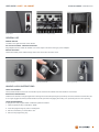
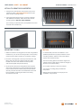
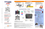
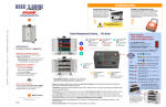
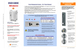
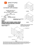
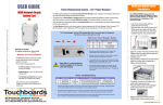
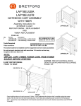
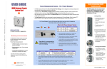
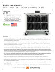
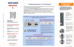
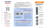
USER GUIDE
STORE & CHARGE | CHGCAB10-CK
CORE™ 10S CABINET
TECHNICAL SPECIFICATIONS
CAUTION
CAPACITY
10 Devices
• Product is for indoor use only
COMPATIBILITY
Chromebook screen sizes up to 13.3” (thickness less than 1”)
Tablet screen sizes up to 13.3” (thickness less than 1” with case)
UNIT DIMENSIONS
20.5”W x 17”D x 18”H
• User can only connect 10 devices at one time
• Turn power switch off before plugging in devices
• Turn power switch off before unplugging the cabinet
• Do not plug the cabinet in if the switch or power
cord has been damaged
SLOT DIMENSIONS
0.875”W x 12”D x 9.25”H
WEIGHT WITHOUT DEVICES
48 lbs.
WARRANTY
12-years, 1-year on electrical
CONSTRUCTION
Steel constructed case with plastic molded slots.
SHIPPING
Ships fully assembled.
1
USER GUIDE | CORE™ 10S CABINET Power Switch
STORE & CHARGE | CHGCAB10-CK
AC Outlet Access - Adapter Storage
Device Storage
GENERAL USE
POWER SWITCH
Located on the right hand side of the cabinet.
AC OUTLET ACCESS - ADAPTER STORAGE
Plug adapters into AC outlets as needed. Use velcro straps to tie down brick type power adapters.
DEVICE STORAGE
Thread associated power cables through slots in AC access door and then close.
Using the Handle
Inserting the Shackle
Lock Programming
HANDLE & LOCK INSTRUCTIONS
USING THE HANDLE
The Flywheel Handle/Lock serves as a handle to open and close the cabinet when the shackle is not inserted.
INSERTING THE SHACKLE
Hold the lock shackle on a slight angle when inserting into the shackle opening and push firmly. Once the shackle is inserted the cam
is no longer engaged and the Flywheel Handle/Lock will spin without engaging the locking cam, preventing the door from opening.
LOCK PROGRAMMING
To program the user programmable combination padlock included:
1. Open the padlock using combination “0000.”
2. Insert the programming key and turn 90 degrees.
3. Set the combination you would like to use.
4. Remove the programming key.
2
USER GUIDE | CORE™ 10S CABINET STORE & CHARGE | CHGCAB10-CK
ATTACH TO DESKTOP/COUNTERTOP
1. Using the two internal holes in the bottom front of the
cabinet as guides, (see orange arrows) drill two pilot
holes into the mounting surface.
2. Using appropriate length screws (customer supplied),
with washers if necessary, fasten the screws into the
mounting surface. DO NOT OVER TIGHTEN.
(For mounting to optional carrier, see separate instructions
included with CTUCAR-CK.)
MOUNTING TO WALL
CAUTION
1. Attach the cabinet mounting plate to the wall using suitable
hardware for your chosen mounting surface. The mounting
method must be able to support up to 220 lbs. (100 kg.).
• For added safety and ease of installation, use a
qualified professional to properly install the correct
mounting hardware. Failure to secure the cabinet
properly will void the warranty.
2. Once the mounting plate is securely mounted to the wall,
lift the plate into place and slide the matching plate
located on the rear of the cabinet into the lip of the
wall-mounted plate. (See pictures above.)
3. To prevent the cabinet from being lifted off of the plate,
secure it by inserting the 2 screws provided through the
holes in the back of the cabinet (see picture) and fasten
securely. Once the front door is locked these screws will
be inaccessible, preventing the cabinet from being
removed from the wall.
Part #031-10018
Rev. 01 03.11.14 RCG
• The wall mounting plate is intended to support the
cabinet and ten mobile devices (maximum weight of
devices not to exceed 40 lbs.).
• Do not place anything on top of the cabinet.
• Use only the mounting plate provided with
this product.
• Bretford will not be liable for the improper use
installation of its products.
3