1
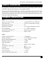
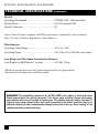
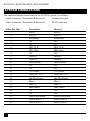
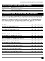
JULY 2007
AC1037A
AC1037A-XMIT
AC1037A-REC
DVI Video with Stereo Audio
Fiber Optic Transmission System
CUSTOMER
SUPPORT
INFORMATION
Order toll-free in the U.S.: Call 877-877-BBOX (outside U.S. call 724-746-5500)
FREE technical support, 24 hours a day, 7 days a week: Call 724-746-5500 or fax 724-746-0746
Mailing address: Black Box Corporation, 1000 Park Drive, Lawrence, PA 15055-1018
Web site: www.blackbox.com • E-mail: [email protected]
AC1037A | AC1037A-XMIT | AC1037A-REC
Trademarks
TRADEMARKS USED IN THIS MANUAL
UL is a registered trademark of Underwriters Laboratories Incorporated.
Any other trademarks used in this manual are acknowledged to be the property of the
trademark owners.
FCC STATEMENT
FEDERAL COMMUNICATIONS COMMISSION AND
CANADIAN DEPARTMENT OF COMMUNICATIONS
RADIO FREQUENCY INTERFERENCE STATEMENTS
This equipment generates, uses, and can radiate radio frequency energy and if not installed
and used properly, that is, in strict accordance with the manufacturer’s instructions, may
cause interference to radio communication. It has been tested and found to comply with
the limits for a Class A computing device in accordance with the specifications in Subpart
B of Part 15 of FCC rules, which are designed to provide reasonable protection against
such interference when the equipment is operated in a commercial environment. Operation
of this equipment in a residential area is likely to cause interference, in which case the user
at his own expense will be required to take whatever measures may be necessary to correct
the interference.
Changes or modifications not expressly approved by the party responsible for compliance
could void the user’s authority to operate the equipment.
This digital apparatus does not exceed the Class A limits for radio noise emission from
digital apparatus set out in the Radio Interference Regulation of the Canadian Department
of Communications.
Le présent appareil numérique n’émet pas de bruits radioélectriques dépassant les limites
applicables aux appareils numériques de la classe A prescrites dans le Règlement sur le
brouillage radioélectrique publié par le ministère des Communications du Canada.
AC1037A | AC1037A-XMIT | AC1037A-REC
NOM STATEMENT
Normas Oficiales Mexicanas (NOM)
Electrical Safety Statement
INSTRUCCIONES DE SEGURIDAD
1. Todas las instrucciones de seguridad y operación deberán ser leídas antes de que el
aparato eléctrico sea operado.
2. Las instrucciones de seguridad y operación deberán ser guardadas para referencia
futura.
3. Todas las advertencias en el aparato eléctrico y en sus instrucciones de operación
deben ser respetadas.
4. Todas las instrucciones de operación y uso deben ser seguidas.
5. El aparato eléctrico no deberá ser usado cerca del agua—por ejemplo, cerca de la
tina de baño, lavabo, sótano mojado o cerca de una alberca, etc.
6. El aparato eléctrico debe ser usado únicamente con carritos o pedestales que sean
recomendados por el fabricante.
7. El aparato eléctrico debe ser montado a la pared o al techo sólo como sea
recomendado por el fabricante.
8. Servicio—El usuario no debe intentar dar servicio al equipo eléctrico más allá a lo
descrito en las instrucciones de operación. Todo otro servicio deberá ser referido a
personal de servicio calificado.
9. El aparato eléctrico debe ser situado de tal manera que su posición no interfiera su
uso. La colocación del aparato eléctrico sobre una cama, sofá, alfombra o superficie
similar puede bloquea la ventilación, no se debe colocar en libreros o gabinetes que
impidan el flujo de aire por los orificios de ventilación.
10. El equipo eléctrico deber ser situado fuera del alcance de fuentes de calor como
radiadores, registros de calor, estufas u otros aparatos (incluyendo amplificadores)
que producen calor.
11. El aparato eléctrico deberá ser connectado a una fuente de poder sólo del tipo
descrito en el instructivo de operación, o como se indique en el aparato.
AC1037A | AC1037A-XMIT | AC1037A-REC
nom statement
(Continued)
12. Precaución debe ser tomada de tal manera que la tierra fisica y la polarización del
equipo no sea eliminada.
13. Los cables de la fuente de poder deben ser guiados de tal manera que no sean
pisados ni pellizcados por objetos colocados sobre o contra ellos, poniendo
particular atención a los contactos y receptáculos donde salen del aparato.
14. El equipo eléctrico debe ser limpiado únicamente de acuerdo a las recomendaciones
del fabricante.
15. En caso de existir, una antena externa deberá ser localizada lejos de las lineas de
energia.
16. El cable de corriente deberá ser desconectado del cuando el equipo no sea usado por
un largo periodo de tiempo.
17. Cuidado debe ser tomado de tal manera que objectos liquidos no sean derramados
sobre la cubierta u orificios de ventilación.
18. Servicio por personal calificado deberá ser provisto cuando:
A: El cable de poder o el contacto ha sido dañado; u
B: Objectos han caído o líquido ha sido derramado dentro del aparato; o
C: El aparato ha sido expuesto a la lluvia; o
D: El aparato parece no operar normalmente o muestra un cambio en
su desempeño; o
E: El aparato ha sido tirado o su cubierta ha sido dañada.
CE INFORMATION
Standards to which conformity is declared:
EN 55103-1:1997
EN 55103-2:1997
AC1037A | AC1037A-XMIT | AC1037A-REC
items included
Depending on which product you ordered, you should have received:
AC1037A-XMIT:
Qty Description
1
AC1037A-XMIT Transmitter
1
Power Supply
1
AC line cord
1
User Manual
AC1037A-REC:
Qty Description
1
1
1
1
AC1037A-REC Receiver
Power Supply
AC line cord
User Manual
AC1037A | AC1037A-XMIT | AC1037A-REC
GENERAL INFORMATION
The AC1037A is a transmitter/receiver pair that transmits a single channel of DVI video (up
to WUXGA) and two audio channels over one single mode fiber.
The system’s all digital encoding delivers noise-free transmissions that retain all of their
initial parameters, regardless of fiber optic cable attenuation. System operation may be easily
monitored using integral indicator LEDs on each unit that continuously signify the presence
of baseband video and audio signals.
TECHNICAL SPECIFICATIONS
Video:
Number of Video Channels...................................... 1 single-link DVI up to 1920x1200
Video Processing......................................................24 bits, no compression or scaling
DVI Input Loop-through..........................................Yes
EDID (DDC) Support...............................................Yes, from loop-through or internal
Pixel Clock Range.................................................... 25 - 165 Mhz, continuous
Scanning System Supported.....................................Progressive or Interlaced
Format Supported..................................................... RGB or YPrPb
Audio:
Number of Audio Channels......................................2, unbalanced
Frequency Response.................................................+0/-0.5 dB, 20 Hz to 20 kHz
Bits-per-Sample/Sampling Rate...............................24 bits; >48kHz
Maximum Audio Level............................................ +10 dBu
SNR (A-Weighted).................................................... 100 dB
THD+N.....................................................................0.001%, 20 Hz - 20 kHz
Channel Phase Differential.......................................+0.1o
Crosstalk...................................................................100 dB (1 kHz)
Input Impedance.......................................................>24 k Ohms
Output Impedance.................................................... < 1 Ohm
Audio to Video Diff. Delay (skew)...........................300 uSec
AC1037A | AC1037A-XMIT | AC1037A-REC
TECHNICAL SPECIFICATIONS
(Continued)
Optical:
Operating Wavelength..............................................CWDM (1300 - 1600 nm band )
Optical Fibers...........................................................8-10/125 microns SM
Optical Connector.....................................................ST
Class I Laser Product complies with FDA performance standard for laser products,
Title 21, Code of Federal Regulations, Sub-Chapter J.
Miscellaneous:
Operating Temp. Range............................................-20oC to +50oC
Operating Power.......................................................9-24 Volts AC or DC@10 watts (max.)
Loss Budget and Maximum Transmission Distance:
Loss Budget (in dB) Distance* (in km)....................0-15 dB, 15 km
*Distance specifications are only approximate and are not guaranteed.
Operating loss budget must not be exceeded.
DANGER! The transmitting element in the AC1037A-XMIT unit contains a solid state Laser
Diode located within the optical connector. This device emits invisible infrared electromagnetic radiation which can be harmful to human eyes. The radiation from this optical connector, if
viewed at close range without a fiber optic cable connected to the optical connector, may be of
sufficient intensity to cause instantaneous damage to the retina of the eye. Direct viewing of this
radiation should be avoided at all times.
AC1037A | AC1037A-XMIT | AC1037A-REC
INSTALLATION
The AC1037A transmission system is ready for immediate use. There are indicator LEDs
on the units for monitoring purposes. The following instructions describe the typical
installation procedure and the function of the LED indicators ( See Page 13 ).
1. Power off the PC and AC1037A Units.
2. Connect the DVI video source (PC) to the video
input DVI-D connector on the transmitter unit.
3. 4. Connect a monitor to the loop-thru input of
transmitter unit if that is the monitor type
to be used on the receiver end of the link.
Ensure that the Loop/Internal EDID Switch
is in the “Loop” position.
If the loop-thru default settings are desired, ensure that the Loop/Internal EDID
Switch is in the “Internal” position. No monitor connection to the transmitter box is
required for this loop-thru position.
Connect the video output(s) on the receiver unit to the DVI-D connector(s).
5. Connect the fiber optic cable between the two AC1037A units.
6. Connect the audio input signals to the transmitter stereo jack and the audio output to
the receiver stereo jack.
7. Apply power to both the AC1037A units and the PC or video source. Refer to Figure 1.
8. When power is applied, the green POWER LED will light, indicating the presence of
operating power. The VIDEO LED will give an indication as described on page 13.
9. The green AUDIO LED will give an indication as stated on page 13.
10. The system should now be operational.
AC1037A | AC1037A-XMIT | AC1037A-REC
system connections
The input and output connections for the AC1037A system is as follows:
Audio Connector (Transmitter & Receiver):
3.5mm stereo jack
Video Connector (Transmitter & Receiver):
DVI-D connector
Video Pin Out:
1
2
3
4
5
6
7
8
9
10
11
12
13
14
15
16
17
18
19
20
21
22
23
24
10
Transmitter
Red (-)
Red (+)
Red Shield
N/C
N/C
DDC CLK
DDC Data
N/C
Green (-)
Green (+)
Green Shield
N/C
N/C
+5V Power
GND (for +5V)
Hot Plug Detect
Blue (-)
Blue (+)
Blue Shield
N/C
N/C
Pixel Click Shield
Pixel Click (+)
Pixel Click (-)
Receiver
Red (-)
Red (+)
Red Shield
N/C
N/C
DDC CLK
DDC Data
N/C
Green(-)
Greeen(+)
Green Shield
N/C
N/C
+5V Power
GND (for +5V)
Hot Plug Detect
Blue (-)
Blue (+)
Blue Shield
N/C
N/C
Pixel Click Shield
Pixel Click (+)
Pixel Click (-)
AC1037A | AC1037A-XMIT | AC1037A-REC
ac1037A-XMIT Edid switch settings
Switch Position
Loop
Internal
EDID Information Source
From loop-thru monitor
Default Settings, Generated Internally
Bandwidth (BW) & Equalizer (EQ) settings
The AC1037A units have a Bandwidth (BW) and Equalizer Setting Dip swicth located on
the front panel. The default factory settings is all switches in the off position. The default
equalizer (EQ) setting is for a short DVI cable, less than 10 feet. The default Bandwidth
(BW) setting is WIDE BW. This should work for most clean, “noise-free” DVI sources.
A narrow bandwidth setting should be used for dirty or noisy DVI sources.
Condition
BW: Wide, EQ: Short Cable (<10 ft.)
BW: Medium, EQ: Short Cable(<10 ft.)
BW: Narrow, EQ: Short Cable (<10 ft.)
BW: Very Narrow, EQ: Short Cable (<10 ft.)
( 1 ) ( 2 ) ( 3 )
Off Off Off
On Off Off
Off On Off
On On Off
(4)
Off
Off
Off
Off
BW: Wide, EQ: Medium Cable (10-20 ft.)
BW: Medium, EQ: Medium Cable (10-20 ft.)
BW: Narrow, EQ: Medium Cable (10-20 ft.)
BW: Very Narrow, EQ: Medium Cable (10-20 ft.)
Off
On
Off
On
Off
Off
On
On
On
On
On
On
Off
Off
Off
Off
BW: Wide, EQ: Long Cable (20-30 ft.)
BW: Medium, EQ: Long Cable (20-30 ft.)
BW: Narrow, EQ: Long Cable (20-30 ft.)
BW: Very Narrow, EQ: Long Cable (20-30 ft.)
Off
On
Off
On
Off
Off
On
On
Off
Off
Off
Off
On
On
On
On
BW: Wide, EQ: Very Long Cable (30-45 ft.)
BW: Medium, EQ: Very Long Cable (30-45 ft.)
BW: Narrow, EQ: Very Long Cable (30-45 ft.)
BW: Very Narrow, EQ: Very Long Cable (30-45 ft.)
Off
On
Off
On
Off
Off
On
On
On
On
On
On
On
On
On
On
11
AC1037A | AC1037A-XMIT | AC1037A-REC
Indicator LED’s
The AC1037A-XMIT and AC1037A-REC units have three integral indicator LEDs that
are used to monitor the state of the units. The status of the LEDs are as follows:
TRANSMITTER and RECEIVER:
Power: ON (GREEN): Indicates that correct power has been
applied.
TRANSMITTER:
Video: OFF: Indicates no video detected on the input.
STEADY GREEN: Indicates DVI Video detected on the input.
Audio: OFF: Indicates no audio detected on the transmitter unit.
BLINKING GREEN: Audio detected on the transmitter unit.
RECEIVER:
Video: OFF: Indicates no video detected over the fiber and, as a result,
no video present on the output.
STEADY GREEN: Indicates DVI Video detected over fiber and, as a result,
video present on the output.
Audio: OFF: Indicates no audio detected over fiber and, as a result,
no active audio detected by the receiver unit.
BLINKING GREEN: Audio detected over fiber and, as a
result, active audio detected by the receiver unit.
12
AC1037A | AC1037A-XMIT | AC1037A-REC
OPERATING pointers & troubleshooting
Optical Cable:
The AC1037A operates with most single mode (SM) optical fibers. However, be aware
that the type of fiber you use will affect the system’s loss budget and the maximum
transmission distance that it can support.
Troubleshooting:
Multimode fiber optic cable contains an optical fiber with a light carrying “core” that is
only .0025 inches (62.5 microns) in diameter. Single mode fiber optic cable has an even
smaller “core,” only .00032 to .0004 inches (8-10 microns). This is smaller than a human
hair!
Therefore, any minute particles of dirt or dust can easily block the fiber from accepting
or radiating light. To prevent this from happening, always use the provided dust caps
whenever optical connectors are exposed to air. It is also a good idea to gently clean the
tip of an optical connector with a lint-free cloth moistened with alcohol whenever dust is
suspected.
The status of the VIDEO and AUDIO indicator LEDs should provide the first clue as to the
origin of an operational failure. If these are off, it usually means that the fiber is broken or
has too much attenuation. Next, be certain that the input and output signal connections are
correct.
If, after reviewing the above possibilities, the system is still not operating, please contact
the Customer Service Department for further assistance.
Maintenance:
The only maintenance of the AC1037A system that can be provided by the user is to
ascertain that the optical connectors are free of dust or dirt that could interfere with light
transmission and that electrical connections are secure and accurate. DANGER! Always
disconnect the transmitter power before removing the optical fiber from the unit! For assistance with all other repairs, please contact Black Box technical support.
13
AC1037A | AC1037A-XMIT | AC1037A-REC
Notes
14
P/N 126650
© Copyright 2007. Black Box Corporation. All rights reserved.
1000 Park Drive • Lawrence, PA 15055-1018 • 724-746-5500 • Fax: 724-746-0746