1
Planar UltraLux Series
Installation Guide
Copyright © 19 Jun 2013 by Planar Systems, Inc. All rights reserved.
Contents of this publication may not be reproduced in any form without permission of Planar
Systems, Inc.
Trademark Credits
Windows™ is a trademark of Microsoft Corp.
All other names are trademarks or registered trademarks of their respective companies.
Disclaimer
The information contained in this document is subject to change without notice. Planar
Systems, Inc. makes no warranty of any kind with regard to this material. While every
precaution has been taken in the preparation of this manual, the Company shall not be liable
for errors or omissions contained herein or for incidental or consequential damages in
connection with the furnishing, performance, or use of this material.
Warranty and Service Plans
Planar warranty and service plans will help you maximize your investment by providing great
support, display uptime, and performance optimization. From post-sale technical support to
a full suite of depot services, our services are performed by trained Planar employees. When
you purchase a Planar product, you get more than a display, you get the service and support
you need to maximize your investment. To find the latest warranty and service information
regarding your Planar product, please visit:
http://www.planar.com/support/warranty/standard_warranties/
Warranty Features
• 3-year protection from defects in material and workmanship
• Advanced shipment of replacement part or product
• Access to 24x7 emergency phone support
• Please visit: http://www.planar.com/support/warranty/standard_warranties/ for a full warranty
review
RoHS Compliance Statement
All Planar UltraLux Series displays are fully RoHS compliant.
ADA Compliance Statement
All Planar UltraLux Series displays are compliant with the Americans with Disabilities Act.
Document Part Number
Part Number: 020-1207-00B
Table of Contents
Introduction . . . . . . . . . . . . . . . . . . . . . . . . . . . . . . . . . . . . . . . . . . . . . . . . . . . . . . . . . . . . . . . . . . . . . . . . . . . . . . . . . . . . . . .1
Planar UltraLux Series Features . . . . . . . . . . . . . . . . . . . . . . . . . . . . . . . . . . . . . . . . . . . . . . . . . . . . . . . . . . . . . . . . . . .2
UltraLux Mounting System. . . . . . . . . . . . . . . . . . . . . . . . . . . . . . . . . . . . . . . . . . . . . . . . . . . . . . . . . . . . . . . . . .3
Control Module. . . . . . . . . . . . . . . . . . . . . . . . . . . . . . . . . . . . . . . . . . . . . . . . . . . . . . . . . . . . . . . . . . . . . . . . . . . . .4
Integrated Media Player Storage . . . . . . . . . . . . . . . . . . . . . . . . . . . . . . . . . . . . . . . . . . . . . . . . . . . . . . . . . . . .5
LED Technology . . . . . . . . . . . . . . . . . . . . . . . . . . . . . . . . . . . . . . . . . . . . . . . . . . . . . . . . . . . . . . . . . . . . . . . . . . . .5
RS232 and LAN With SNMP Monitoring. . . . . . . . . . . . . . . . . . . . . . . . . . . . . . . . . . . . . . . . . . . . . . . . . . . . . .5
Remote Control . . . . . . . . . . . . . . . . . . . . . . . . . . . . . . . . . . . . . . . . . . . . . . . . . . . . . . . . . . . . . . . . . . . . . . . . . . . . . . . . . .6
IR Sensor . . . . . . . . . . . . . . . . . . . . . . . . . . . . . . . . . . . . . . . . . . . . . . . . . . . . . . . . . . . . . . . . . . . . . . . . . . . . . . . . . . . . . . . . .7
Safety Information . . . . . . . . . . . . . . . . . . . . . . . . . . . . . . . . . . . . . . . . . . . . . . . . . . . . . . . . . . . . . . . . . . . . . . . . . . . . . . .8
Important Safety Instructions . . . . . . . . . . . . . . . . . . . . . . . . . . . . . . . . . . . . . . . . . . . . . . . . . . . . . . . . . . . . . . .8
European Union Disposal Information. . . . . . . . . . . . . . . . . . . . . . . . . . . . . . . . . . . . . . . . . . . . . . . . . . . . . 10
Recommended Usage . . . . . . . . . . . . . . . . . . . . . . . . . . . . . . . . . . . . . . . . . . . . . . . . . . . . . . . . . . . . . . . . . . . . . . . . . . 11
Burn-In Versus Temporary Image Retention . . . . . . . . . . . . . . . . . . . . . . . . . . . . . . . . . . . . . . . . . . . . . . . 11
Normal Use Thermal Guidelines . . . . . . . . . . . . . . . . . . . . . . . . . . . . . . . . . . . . . . . . . . . . . . . . . . . . . . . . . . . 12
Installing the Planar UltraLux Series . . . . . . . . . . . . . . . . . . . . . . . . . . . . . . . . . . . . . . . . . . . . . . . . . . . . . . . . . . . . . 13
Before You Begin . . . . . . . . . . . . . . . . . . . . . . . . . . . . . . . . . . . . . . . . . . . . . . . . . . . . . . . . . . . . . . . . . . . . . . . . . . . . . . .
Tools/Equipment List . . . . . . . . . . . . . . . . . . . . . . . . . . . . . . . . . . . . . . . . . . . . . . . . . . . . . . . . . . . . . . . . . . . . .
Other Things You May Need . . . . . . . . . . . . . . . . . . . . . . . . . . . . . . . . . . . . . . . . . . . . . . . . . . . . . . . . . . . . . .
Plan Your Installation . . . . . . . . . . . . . . . . . . . . . . . . . . . . . . . . . . . . . . . . . . . . . . . . . . . . . . . . . . . . . . . . . . . . .
13
13
13
13
Powering On/Off Displays . . . . . . . . . . . . . . . . . . . . . . . . . . . . . . . . . . . . . . . . . . . . . . . . . . . . . . . . . . . . . . . . . . . . . . 14
Unpacking and Checking Accessories . . . . . . . . . . . . . . . . . . . . . . . . . . . . . . . . . . . . . . . . . . . . . . . . . . . . . . . . . . . 15
Accessory Kit . . . . . . . . . . . . . . . . . . . . . . . . . . . . . . . . . . . . . . . . . . . . . . . . . . . . . . . . . . . . . . . . . . . . . . . . . . . . . 15
Optional Planar-Supplied Accessories . . . . . . . . . . . . . . . . . . . . . . . . . . . . . . . . . . . . . . . . . . . . . . . . . . . . . 16
Wall Mounting LCD Using Planar Profile Mount. . . . . . . . . . . . . . . . . . . . . . . . . . . . . . . . . . . . . . . . . . . . . . . . . . 17
Installing an LCD Module on a Wall Using Planar Profile Mount . . . . . . . . . . . . . . . . . . . . . . . . . . . . . . . . . . 17
Landscape Installation . . . . . . . . . . . . . . . . . . . . . . . . . . . . . . . . . . . . . . . . . . . . . . . . . . . . . . . . . . . . . . . . . . . . 17
Portrait Installation . . . . . . . . . . . . . . . . . . . . . . . . . . . . . . . . . . . . . . . . . . . . . . . . . . . . . . . . . . . . . . . . . . . . . . . 22
Planar UltraLux Series Installation Guide
i
Table of Contents
Installing Cables . . . . . . . . . . . . . . . . . . . . . . . . . . . . . . . . . . . . . . . . . . . . . . . . . . . . . . . . . . . . . . . . . . . . . . . . . . . . . . . . . .28
Touchscreen Setup. . . . . . . . . . . . . . . . . . . . . . . . . . . . . . . . . . . . . . . . . . . . . . . . . . . . . . . . . . . . . . . . . . . . . . . . . . . . . . . .29
USB and Power Hook-Up . . . . . . . . . . . . . . . . . . . . . . . . . . . . . . . . . . . . . . . . . . . . . . . . . . . . . . . . . . . . . . . . . . . . . . . .29
Touchscreen MultiTouch Driver Installation . . . . . . . . . . . . . . . . . . . . . . . . . . . . . . . . . . . . . . . . . . . . . . . . . . . . . .30
Touchscreen (PQLabs) MultiTouch Platform Content . . . . . . . . . . . . . . . . . . . . . . . . . . . . . . . . . . . . . . . . . . . . .30
Touchscreen Information . . . . . . . . . . . . . . . . . . . . . . . . . . . . . . . . . . . . . . . . . . . . . . . . . . . . . . . . . . . . . . . . . .30
Calibration . . . . . . . . . . . . . . . . . . . . . . . . . . . . . . . . . . . . . . . . . . . . . . . . . . . . . . . . . . . . . . . . . . . . . . . . . . . . . . . .30
Utility . . . . . . . . . . . . . . . . . . . . . . . . . . . . . . . . . . . . . . . . . . . . . . . . . . . . . . . . . . . . . . . . . . . . . . . . . . . . . . . . . . . . .30
Options . . . . . . . . . . . . . . . . . . . . . . . . . . . . . . . . . . . . . . . . . . . . . . . . . . . . . . . . . . . . . . . . . . . . . . . . . . . . . . . . . . .31
Uninstalling the MultiTouch Driver . . . . . . . . . . . . . . . . . . . . . . . . . . . . . . . . . . . . . . . . . . . . . . . . . . . . . . . . . . . . . .31
External Control and Monitoring . . . . . . . . . . . . . . . . . . . . . . . . . . . . . . . . . . . . . . . . . . . . . . . . . . . . . . . . . . . . . . . . .33
RS232 Communication . . . . . . . . . . . . . . . . . . . . . . . . . . . . . . . . . . . . . . . . . . . . . . . . . . . . . . . . . . . . . . . . . . . . . . . . . .34
Connecting the RS232 Cable. . . . . . . . . . . . . . . . . . . . . . . . . . . . . . . . . . . . . . . . . . . . . . . . . . . . . . . . . . . . . . .34
RS232 Commands. . . . . . . . . . . . . . . . . . . . . . . . . . . . . . . . . . . . . . . . . . . . . . . . . . . . . . . . . . . . . . . . . . . . . . . . . . . . . . .35
SNMP Monitoring . . . . . . . . . . . . . . . . . . . . . . . . . . . . . . . . . . . . . . . . . . . . . . . . . . . . . . . . . . . . . . . . . . . . . . . . . . . . . . .37
Sending RS232 Commands Via UDP . . . . . . . . . . . . . . . . . . . . . . . . . . . . . . . . . . . . . . . . . . . . . . . . . . . . . . . . . . . . .38
Using WallNet Assistant . . . . . . . . . . . . . . . . . . . . . . . . . . . . . . . . . . . . . . . . . . . . . . . . . . . . . . . . . . . . . . . . . . . . . . . . .39
Route Add Command . . . . . . . . . . . . . . . . . . . . . . . . . . . . . . . . . . . . . . . . . . . . . . . . . . . . . . . . . . . . . . . . . . . . .42
Planar UltraLux Remote Monitoring. . . . . . . . . . . . . . . . . . . . . . . . . . . . . . . . . . . . . . . . . . . . . . . . . . . . . . . . . . . . . .43
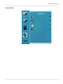
Remote Monitoring Home . . . . . . . . . . . . . . . . . . . . . . . . . . . . . . . . . . . . . . . . . . . . . . . . . . . . . . . . . . . . . . . . .43
Unit Status . . . . . . . . . . . . . . . . . . . . . . . . . . . . . . . . . . . . . . . . . . . . . . . . . . . . . . . . . . . . . . . . . . . . . . . . . . . . . . . .44
Display Control. . . . . . . . . . . . . . . . . . . . . . . . . . . . . . . . . . . . . . . . . . . . . . . . . . . . . . . . . . . . . . . . . . . . . . . . . . . .45
Admin Setup . . . . . . . . . . . . . . . . . . . . . . . . . . . . . . . . . . . . . . . . . . . . . . . . . . . . . . . . . . . . . . . . . . . . . . . . . . . . . .48
Reboot. . . . . . . . . . . . . . . . . . . . . . . . . . . . . . . . . . . . . . . . . . . . . . . . . . . . . . . . . . . . . . . . . . . . . . . . . . . . . . . . . . . .54
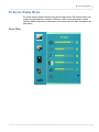
On-Screen Display Menus . . . . . . . . . . . . . . . . . . . . . . . . . . . . . . . . . . . . . . . . . . . . . . . . . . . . . . . . . . . . . . . . . . . . . . .55
Image Menu . . . . . . . . . . . . . . . . . . . . . . . . . . . . . . . . . . . . . . . . . . . . . . . . . . . . . . . . . . . . . . . . . . . . . . . . . . . . . .55
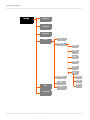
Display Menu . . . . . . . . . . . . . . . . . . . . . . . . . . . . . . . . . . . . . . . . . . . . . . . . . . . . . . . . . . . . . . . . . . . . . . . . . . . . .57
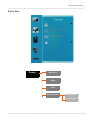
Sound Menu . . . . . . . . . . . . . . . . . . . . . . . . . . . . . . . . . . . . . . . . . . . . . . . . . . . . . . . . . . . . . . . . . . . . . . . . . . . . . .58
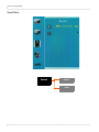
System Menu . . . . . . . . . . . . . . . . . . . . . . . . . . . . . . . . . . . . . . . . . . . . . . . . . . . . . . . . . . . . . . . . . . . . . . . . . . . . .59
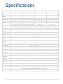
Specifications. . . . . . . . . . . . . . . . . . . . . . . . . . . . . . . . . . . . . . . . . . . . . . . . . . . . . . . . . . . . . . . . . . . . . . . . . . . . . . . . . . . . .61
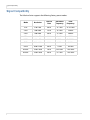
Signal Compatibility. . . . . . . . . . . . . . . . . . . . . . . . . . . . . . . . . . . . . . . . . . . . . . . . . . . . . . . . . . . . . . . . . . . . . . . . . . . . .62
ii
Planar UltraLux Series Installation Guide
Table of Contents
UltraLux Dimensions. . . . . . . . . . . . . . . . . . . . . . . . . . . . . . . . . . . . . . . . . . . . . . . . . . . . . . . . . . . . . . . . . . . . . . . . . . . . . 63
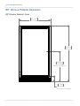
70” LCD Module Dimensions. . . . . . . . . . . . . . . . . . . . . . . . . . . . . . . . . . . . . . . . . . . . . . . . . . . . . . . . . . . . . . . . . . . .
70” LCD Front View - Landscape. . . . . . . . . . . . . . . . . . . . . . . . . . . . . . . . . . . . . . . . . . . . . . . . . . . . . . . . . . .
70” LCD Rear View - Landscape. . . . . . . . . . . . . . . . . . . . . . . . . . . . . . . . . . . . . . . . . . . . . . . . . . . . . . . . . . . .
70” LCD Side View - Landscape. . . . . . . . . . . . . . . . . . . . . . . . . . . . . . . . . . . . . . . . . . . . . . . . . . . . . . . . . . . .
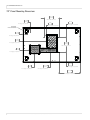
70” Panel Mounting Dimensions . . . . . . . . . . . . . . . . . . . . . . . . . . . . . . . . . . . . . . . . . . . . . . . . . . . . . . . . . .
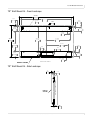
70” Wall Mount Kit - Front Landscape . . . . . . . . . . . . . . . . . . . . . . . . . . . . . . . . . . . . . . . . . . . . . . . . . . . . .
70” Wall Mount Kit - Side Landscape. . . . . . . . . . . . . . . . . . . . . . . . . . . . . . . . . . . . . . . . . . . . . . . . . . . . . . .
70” Wall Mount Kit - Front Portrait. . . . . . . . . . . . . . . . . . . . . . . . . . . . . . . . . . . . . . . . . . . . . . . . . . . . . . . . .
70” LCD Touch View - Front . . . . . . . . . . . . . . . . . . . . . . . . . . . . . . . . . . . . . . . . . . . . . . . . . . . . . . . . . . . . . . .
70” LCD Touch View - Rear . . . . . . . . . . . . . . . . . . . . . . . . . . . . . . . . . . . . . . . . . . . . . . . . . . . . . . . . . . . . . . . .
70” LCD Touch View - Side . . . . . . . . . . . . . . . . . . . . . . . . . . . . . . . . . . . . . . . . . . . . . . . . . . . . . . . . . . . . . . . .
63
63
64
65
66
67
67
68
70
71
72
80” LCD Module Dimensions. . . . . . . . . . . . . . . . . . . . . . . . . . . . . . . . . . . . . . . . . . . . . . . . . . . . . . . . . . . . . . . . . . . .
80” LCD Front View - Landscape. . . . . . . . . . . . . . . . . . . . . . . . . . . . . . . . . . . . . . . . . . . . . . . . . . . . . . . . . . .
80” LCD Rear View - Landscape. . . . . . . . . . . . . . . . . . . . . . . . . . . . . . . . . . . . . . . . . . . . . . . . . . . . . . . . . . . .
80” LCD Side View - Landscape. . . . . . . . . . . . . . . . . . . . . . . . . . . . . . . . . . . . . . . . . . . . . . . . . . . . . . . . . . . .
80” Panel Mounting Dimensions . . . . . . . . . . . . . . . . . . . . . . . . . . . . . . . . . . . . . . . . . . . . . . . . . . . . . . . . . .
80” Wall Mount Kit - Front Landscape . . . . . . . . . . . . . . . . . . . . . . . . . . . . . . . . . . . . . . . . . . . . . . . . . . . . .
80” Wall Mount Kit - Side Landscape. . . . . . . . . . . . . . . . . . . . . . . . . . . . . . . . . . . . . . . . . . . . . . . . . . . . . . .
80” Wall Mount Kit - Front Portrait. . . . . . . . . . . . . . . . . . . . . . . . . . . . . . . . . . . . . . . . . . . . . . . . . . . . . . . . .
80” Wall Mount Kit - Side Portrait . . . . . . . . . . . . . . . . . . . . . . . . . . . . . . . . . . . . . . . . . . . . . . . . . . . . . . . . . .
80” LCD Touch View - Front . . . . . . . . . . . . . . . . . . . . . . . . . . . . . . . . . . . . . . . . . . . . . . . . . . . . . . . . . . . . . . .
80” LCD Touch View - Rear . . . . . . . . . . . . . . . . . . . . . . . . . . . . . . . . . . . . . . . . . . . . . . . . . . . . . . . . . . . . . . . .
80” LCD Touch View - Side . . . . . . . . . . . . . . . . . . . . . . . . . . . . . . . . . . . . . . . . . . . . . . . . . . . . . . . . . . . . . . . .
73
73
74
75
76
77
77
78
79
80
81
82
Media Compartment Player Dimensions . . . . . . . . . . . . . . . . . . . . . . . . . . . . . . . . . . . . . . . . . . . . . . . . . . . . . . . . 83
UltraLux Pedestals . . . . . . . . . . . . . . . . . . . . . . . . . . . . . . . . . . . . . . . . . . . . . . . . . . . . . . . . . . . . . . . . . . . . . . . . . . . . . . . 85
Installing the UltraLux on the Pedestal Mount . . . . . . . . . . . . . . . . . . . . . . . . . . . . . . . . . . . . . . . . . . . . . . . . . . . 85
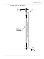
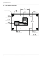
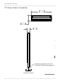
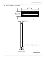
70” UltraLux Pedestal Dimensions. . . . . . . . . . . . . . . . . . . . . . . . . . . . . . . . . . . . . . . . . . . . . . . . . . . . . . . . . . . . . . .
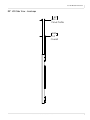
70” UltraLux Pedestal - Front . . . . . . . . . . . . . . . . . . . . . . . . . . . . . . . . . . . . . . . . . . . . . . . . . . . . . . . . . . . . . .
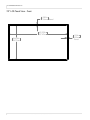
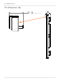
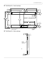
70” UltraLux Pedestal - Top and Side . . . . . . . . . . . . . . . . . . . . . . . . . . . . . . . . . . . . . . . . . . . . . . . . . . . . . .
70” UltraLux Pedestal - Anchor Dimensions . . . . . . . . . . . . . . . . . . . . . . . . . . . . . . . . . . . . . . . . . . . . . . . .
87
87
88
89
80” UltraLux Pedestal Dimensions. . . . . . . . . . . . . . . . . . . . . . . . . . . . . . . . . . . . . . . . . . . . . . . . . . . . . . . . . . . . . . .
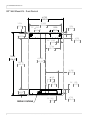
80” UltraLux Pedestal - Front . . . . . . . . . . . . . . . . . . . . . . . . . . . . . . . . . . . . . . . . . . . . . . . . . . . . . . . . . . . . . .
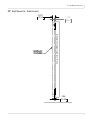
80” UltraLux Pedestal - Top and Side . . . . . . . . . . . . . . . . . . . . . . . . . . . . . . . . . . . . . . . . . . . . . . . . . . . . . .
80” UltraLux Pedestal - Anchor Dimensions . . . . . . . . . . . . . . . . . . . . . . . . . . . . . . . . . . . . . . . . . . . . . . . .
90
90
91
92
Accessing Planar’s Technical Support Website . . . . . . . . . . . . . . . . . . . . . . . . . . . . . . . . . . . . . . . . . . . . . . . . . . . 93
Downloading Additional Documentation and Software . . . . . . . . . . . . . . . . . . . . . . . . . . . . . . . . . . . . . . . . . 93
Planar UltraLux Series Installation Guide
iii
Table of Contents
Downloading Utility Software . . . . . . . . . . . . . . . . . . . . . . . . . . . . . . . . . . . . . . . . . . . . . . . . . . . . . . . . . . . . . . . . . . .93
Field Replaceable Units (FRUs) . . . . . . . . . . . . . . . . . . . . . . . . . . . . . . . . . . . . . . . . . . . . . . . . . . . . . . . . . . . . . . . . . . .93
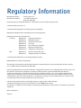
Regulatory Information. . . . . . . . . . . . . . . . . . . . . . . . . . . . . . . . . . . . . . . . . . . . . . . . . . . . . . . . . . . . . . . . . . . . . . . . . . .95
Customer Support Information . . . . . . . . . . . . . . . . . . . . . . . . . . . . . . . . . . . . . . . . . . . . . . . . . . . . . . . . . . . . . . . . . . .96
Customer Support Contact Information and Hours of Operation . . . . . . . . . . . . . . . . . . . . . . . . . . . . . . . . . .96
Warranty and Service Plans . . . . . . . . . . . . . . . . . . . . . . . . . . . . . . . . . . . . . . . . . . . . . . . . . . . . . . . . . . . . . . . . . . . . . .96
Warranty Features . . . . . . . . . . . . . . . . . . . . . . . . . . . . . . . . . . . . . . . . . . . . . . . . . . . . . . . . . . . . . . . . . . . . . . . . .96
iv
Planar UltraLux Series Installation Guide
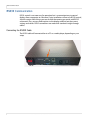
Introduction
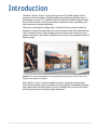
The Planar UltraLux Series is a family of large format 70" and 80" displays which
combine style and aesthetics with high performance display technology. From its
sleek design to lasting 24 x 7 reliability, the Planar UltraLux is ideally suited for retail
brand communications, advertising networks, conference rooms, wayfinding, and
other commercial signage applications.
Offered in a wide range of configurations, the Planar UltraLux Series provides the
flexibility to specify the ideal display for any environment. With value added features
such as interactive touch, edge-to-edge glass front design, and unique mounting
options, the UltraLux goes above and beyond for a truly stunning implementation of
digital signage.
Caution: This manual is intended for use by qualified service persons and end users with
experience installing LCD displays.
Planar UltraLux Series is wall mountable in portrait or landscape configurations.
Planar UltraLux displays are also available in single or double-sided pedestal displays.
Each model within the Planar UltraLux Series is available with six-point multi-touch
technology for interactive digital signage applications.
Planar UltraLux Series Installation Guide
1
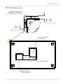
Planar UltraLux Series Features
Planar UltraLux Series Features
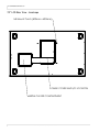
The Planar UltraLux Series delivers superior 24/7 visual performance shown in a lower
total cost of ownership (TCO) compared to other large-format digital signage
displays.
Integrated media
player compartment
Cable box
Control
module/redundant
power supply
Kickstand
stop bracket
Mounting
bracket
Caution: AC power cord needs to be away from the three component boxes shown here.
This is due to the very low profile of the space between the back of the LCD and the wall.
2
Planar UltraLux Series Installation Guide
Planar UltraLux Series Features
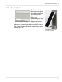
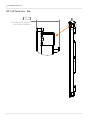
UltraLux Mounting System
The Planar Profile™
Mounting System allows
for simplified installation.
The Profile Mounting
System includes two wall
brackets and
incorporates a kick-stand
feature that tilts the
display away from the
Wall mount brackets - landscape
wall for easy access to the
electronics. Eliminating the need to completely remove
the display from the wall reduces complexity and service
time by up to 70%.
Profile™ Mounting System with
kick-stand service mode
Planar UltraLux Series Installation Guide
3
Planar UltraLux Series Features
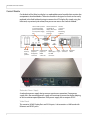
Control Module
On the back of the UltraLux display is a replaceable control module that contains the
components described below. The entire module is designed so that it can be easily
replaced in the field without having to remove the LCD display. By simply using the
kickstand, as previously described, one person can access the control module.
Leave in “Run” position
to ensure backlight
power is reduced by
50% if a power supply
fails.
L
R
Used to send serial
commands to
display. Also used
for diagnostic
purposes.
Used to
connect to
Remote
Monitoring
software.
RS-232
RUN
SVC
ETHERNET
AUDIO OUT DISPLAY PORT
Used to
hook up
audio
speakers.
HDMI
Used If media
player has
DisplayPort
connector.
AUDIO IN
VGA
Used If media
player has
HDMI
connector.
Audio
Used If
media player In jack
has VGA
connector.
Power cord
connector
AC power
switch
Redundant Power Supply
A redundant power supply design ensures continuous operation. If one power
supply fails, the remaining power supply will continue to power the display helping
to ensure uninterrupted operation. Each power supply has an output of 24V.
Video Board
This contains HDMI, DisplayPort and VGA inputs. It also contains a LAN board with
Ethernet and RS232 ports.
4
Planar UltraLux Series Installation Guide
Planar UltraLux Series Features
Power Board
This is used to generate the required voltages needed to run the control module.
Integrated Media Player Storage
Planar UltraLux displays incorporate a 1U media player compartment enabling a
fully-integrated digital signage display system that can power a 5V or 12V media
player up to 3A on each supply.
LED Technology
With 700 nits, FHD 1920 x 1080 (1080p) edge-lit LED technology, the Planar UltraLux
Series delivers reduced power consumption and lowered operating costs over the life
of the display by up to 60% compared to CCFL technology.
RS232 and LAN With SNMP Monitoring
Control and status monitoring and integration with enterprise management
solutions.
Planar UltraLux Series Installation Guide
5
Remote Control
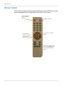
Remote Control
All on-screen functions can be accessed using the remote control. Note that only the
buttons highlighted below are applicable to the UltraLux Series panels.
Turns on/off the AC
power to the LCD
module.
Four arrow keys
move the selector as
shown: up, down,
left or right.
Mutes the audio.
Press to access on-screen
menus.
Select this to choose a source.
Also use as the Back button
when navigating through
menus.
6
Planar UltraLux Series Installation Guide
IR Sensor
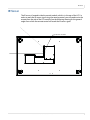
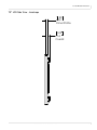
IR Sensor
The IR sensor is located inside the control module, which is in the rear of the LCD. In
order to reach the IR sensor signal using the remote control, you will need to aim the
remote from the side of the LCD module. See the following drawing for the general
angles from which the remote control will reach the IR sensor signal.
,56HQVRU/RFDWLRQ
Planar UltraLux Series Installation Guide
7
Safety Information
Safety Information
This display was designed with safety in mind. If you don’t heed the safety warnings
and cautions, you could get hurt. The safety warnings are on stickers in various places
in and on the display.
Important Safety Instructions
1
Read these instructions.
2
Keep these instructions.
3
Heed all warnings.
4
Follow all instructions.
5
Do not use any of the Planar UltraLux Series products near water.
6
Clean the optically bonded protection glass (EROTM) with a 50-50 mix of water and
isopropyl alcohol with cheesecloth.
7
Do not install near any heat sources such as radiators, heat registers, stoves or
other apparatus (including amplifiers) that produce heat.
8
Do not defeat the safety purpose of the polarized or grounding type plug. A
polarized plug has two blades with one wider than the other. A grounding type
plug has two blades and a third grounding prong. The wide blade or the third
prong is provided for your safety. When the provided plug does not fit into your
outlet, consult an electrician for the replacement of the obsolete outlet.
9
Protect the power cord from being walked on or pinched particularly at plugs,
convenience receptacles and the point where they exit from any of the Planar
UltraLux Series products.
10 The AC input is protected by a 5A slow blow fuse located in the AC inlet module.
The fuse is replaceable and the recommended fuse is Schurter part number
0034.3124.
11 Only use the attachments/accessories specified by the manufacturer.
12 Unplug all Planar UltraLux Series products during lightning storms or when
unused for long periods of time.
13 Ensure that the RUN/SVC switch on the control module is in the “Run” position
unless the display is being serviced. This will ensure that if one power supply fails
that the backlights will be reduced by 50% to save power.
8
Planar UltraLux Series Installation Guide
Safety Information
14 You must follow all National Electrical Code regulations. In addition, be aware of
local codes and ordinances when installing your system.
15 Refer all servicing to qualified service personnel. Servicing is required when any
of the Planar UltraLux Series displays have been damaged in any way, such as the
AC power cord or plug is damaged, liquid has been spilled or objects have fallen
into the display, or if the displays have been exposed to rain or moisture, do not
operate normally or have been dropped.
16 Keep the packing material in case the equipment should ever need to be
shipped.
17 Wall mounts must be secure. The wall must be strong enough to hold all displays,
mounts, brackets and cables.
18 Slight pressure on the LCD will cause distortion of the image. Heavier pressure
will cause permanent damage. Planar UltraLux Series configurations should be
mounted in a way that viewers cannot insert small objects in the openings that
will create hazards by contacting bare conductive parts.
Planar UltraLux Series Installation Guide
9
Safety Information
European Union Disposal Information
English
■ Disposal of old Electrical & Electronic Equipment (Applicable throughout
the European Union and other European countries with separate collection
programs)
Français
■ Mise au rebut des équipements électriques et électroniques usagés
(Valable dans l’ensemble de l’Union Européenne ainsi que dans les pays
européens disposant de programmes distincts de collecte des déchets)
This symbol found on your product or on its packaging, indicates that
this product should not be treated as household waste when you wish to
dispose of it. Instead, it should be handed over to an applicable collection
point for the recycling of electrical and electronic equipment. By ensuring
this product is disposed of correctly, you will help prevent potential
negative consequences to the environment and human health, which
could otherwise be caused by inappropriate disposal of this product. The
recycling of materials will help to conserve natural resources.
Ce symbole appliqué sur votre produit ou sur son emballage indique
que ce produit ne doit pas être traité comme un déchet ménager lorsque
vous voulez le mettre au rebut. Il doit au contraire être remis à un site
de collecte agréé pour le recyclage des équipements électriques et
électroniques. En veillant à ce que ce produit soit mis au rebut de façon
adéquate, vous contribuerez à prévenir les conséquences potentiellement
négatives sur l’environnement et sur la santé humaine qui risqueraient
de se produire en cas de mise au rebut inappropriée de ce produit. Le
recyclage des matériaux contribuera également à économiser les ressources naturelles.
Dieses Symbol, zu finden auf Ihrem Produkt oder dessen Verpackung,
macht Sie darauf aufmerksam, dass dieses Produkt bei der Entsorgung
nicht als Hausmüll behandelt werden darf. Statt dessen sollte es an eine
Sammelstelle zum Recycling von elektrischen und elektronischen Altgeräten gegeben werden. Helfen Sie mit, potenziell schädliche Einflüsse
auf Umwelt und Gesundheit, die durch eine unsachgemäße Entsorgung
dieses Produktes entstehen können, zu vermeiden und entsorgen Sie
dieses Produkt ordnungsgemäß. Recycling hilft, natürliche Rohstoffe
einzusparen.
This symbol is only valid in the European Union.
If you wish to discard this product, please contact
your local authorities or dealer and ask for the correct method of disposal.
Ce symbole n’est valable que dans l’Union Européenne.
Si vous souhaitez mettre ce produit au rebut, veuillez
prendre contact avec les autorités locales ou avec votre
revendeur et renseignez-vous sur la méthode de mise
au rebut correcte.
Dieses Symbol ist nur innerhalb der europäischen
Gemeinschaft gültig.
Wenn Sie dieses Produkt entsorgen möchten, wenden
Sie sich bitte an Ihre örtliche Behörde und fragen Sie
nach der ordnungsgemäßen Entsorgungsmethode.
Español
■ Deshecho de equipos eléctricos y electrónicos (aplicable a la Unión Europea y a otros países europeos con programas de reciclaje independientes)
La presencia de este símbolo en el propio producto o en su material de
embalaje, indica que no se debe tratar como residuo doméstico cuando
desee deshacerse de él. En su lugar, debe entregarlo en el punto limpio
correspondiente de reciclaje de equipos eléctricos y electrónicos. Asegurándose de que este producto se desecha de forma correcta, ayudará
a evitar posibles consecuencias negativas para la conservación del
medioambiente y la salud humana, consecuencias que podrían darse si
se deshace del producto de forma inadecuada. El reciclado de materiales
ayuda a conservar los recursos naturales.
Este símbolo solamente es válido en la Unión
Europea.
Si desea deshacerse de este producto, póngase
en contacto con las autoridades locales o con su
distribuidor y pida información sobre el método de
disposición adecuado.
Italiano
■ Smaltimento delle attrezzature elettriche ed elettroniche usate (applicabile
in tutta la Comunità Europea ed altri Paesi Europei che applicano
programmi di raccolta differenziata)
Il simbolo trovato sul prodotto, o sulla sua confezione, indica che il
prodotto non può essere trattato come i domestici quando è il momento
di smaltirlo. Al contrario, deve essere consegnato ad un centro di raccolta
specializzato nel riciclaggio di attrezzature elettriche ed elettroniche. Assicurando che il corretto smaltimento di questo prodotto, si aiuterà a prevenire potenziali conseguenze negative sull’ambiente e sulla salute umana,
che possono essere provocate da uno scorretto smaltimento di questa
attrezzatura. I materiali riciclati aiuteranno a conservare le risorse naturali.
Questo simbolo è valido solo nell’Unione Europea.
Per smaltire questo prodotto, mettersi in contatto con
le autorità locali – o con il rivenditore – e chiedere
informazioni sul corretto metodo di smaltimento.
Português
■ Eliminação de equipamentos eléctricos e electrónicos usados (aplicável
na União Europeia e noutros países europeus com programas próprios de
recolha destes equipamentos)
Este símbolo, colocado no produto ou na respectiva embalagem, indica
que o produto não deve ser tratado como lixo doméstico aquando da sua
eliminação. Em vez disso, deve ser entregue num ponto de recolha de equipamentos eléctricos e electrónicos para posterior reciclagem. Ao garantir
a correcta eliminação deste produto, estará a evitar consequências potencialmente negativas tanto para o ambiente como para a saúde humana. A
reciclagem de materiais ajuda a preservar os recursos naturais.
Este símbolo apenas é válido na União Europeia.
Se quiser eliminar este produto, contacte as entidades locais ou o seu fornecedor para ficar a saber
qual o método de eliminação correcto.
Obecność tego symbolu na produkcie lub na opakowaniu z produktem
oznacza, że tego produktu nie można wyrzucać razem z odpadkami
domowymi. Należy go przekazać do punktu zbiórki w celu poddania
recyklingowi podzespołów elektrycznych i elektronicznych. Usunięcie tego
produktu w prawidłowy sposób, pomoże w zabezpieczeniu przed negatywnym wpływem odpadów na środowisko i zdrowie ludzi, powodowanym
przez niewłaściwe usuwanie produktu. Przetwarzanie materiałów pomaga
w zachowaniu zasobów naturalnych.
Ten symbol obowiązuje wyłącznie w krajach Unii
Europejskiej.
Informacje dotyczące prawidłowej metody usunięcia
tego produktu, można uzyskać u władz lokalnych lub
u dostawcy.
■ Avfall av förbrukad elektrisk och elektronisk utrustning (Tillämpbart i
hela Europeiska unionen och andra europeiska länder med separata
samlingsprogram)
Den här symbolen är endast giltig inom den
Europeiska unionen.
Om du vill slänga bort den här produkten ska du
kontakta lokala myndigheter eller återförsäljar, och
fråga efter lämplig avfallsmetod.
Dit symbool dat op het product of zijn verpakking is aangebracht, geeft aan
dat dit product niet mag worden behandeld als huishoudelijk afval als u het
wilt wegwerpen. U moet het afgeven bij een specifiek verzamelpunt voor
de recyclage van elektrische en elektronische apparatuur. Door te garanderen dat u dit product op de correcte manier wegwerpt, helpt u potentiële
negatieve gevolgen voor het milieu en de menselijke gezondheid, die
zouden kunnen worden veroorzaakt door een onrechtmatig wegwerpen
van het product, te voorkomen. De recyclage van materialen helpt het
behoud van natuurlijke bronnen.
Dit symbool is alleen geldig in de Europese Unie.
Als u dit product wenst weg te gooien, dient u contact op
te nemen met uw lokale instanties voor details over de
gepaste methode voor afvalverwijdering.
Waste Electrical and Electronic Equipment (WEEE) Directive In the European Union, this label indicates that this product should not be disposed of with household waste. It should be deposited at an appropriate facility to enable recovery and recycling. EEE complies with Directive ‘Regulation on the Restriction of the Use of Certain Hazardous Substances in Electrical and Electronic Equipment’
Waste Electrical and Electronic Equipment (WEEE) Directive In the European Union, this label indicates that this product should not be disposed of with household waste. It should be deposited at an appropriate facility to enable recovery and recycling. EEE complies with Directive ‘Regulation on the Restriction of the Use of Certain Hazardous Substances in Electrical and Electronic Equipment’
Suomi
■ Vanhojen sähkö- ja elektroniikkalaitteiden hävittäminen (Soveltuva kaikkialla Euroopan unionin alueella, sekä muissa Euroopan maissa, joilla on
erilliset keräysohjelmat)
Den här symbolen som finns på din product eller på dess förpackning
påvisar att produkten inte ska behandlas som hushållsavfall när du vill
slänga bort den. Istället ska den lämnas över till en lämplig uppsamlingspunkt för återvinning av elektriska och elektroniska utrustningar. Genom att
tillförsäkra att den här produkten återvinns på ett riktigt sätt hjälper du till
med att förhindra möjliga negative konsekvenser för miljön och mänsklig
hälsa. Det kan annars orsakas på grund av olämplig sophantering av den
här produkten. Återvinning av material kommer att hjälpa till att bevara
naturtillgångar.
Nederlands
■ Verwijderen van oude elektrische en elektronische apparatuur (toepasselijk in de volledige Europese Unie en andere Europese landen met
afzonderlijke programma’s voor afvalverzameling)
Polski
■ Usuwanie zużytego sprzętu elektrycznego i elektronicznego (Dotyczy
krajów Unii Europejskiej i innych krajów europejskich z oddzielnymi
programami zbiórki odpadów)
Svenska
10
Deutsch
■ Entsorgung von elektrischen & elektronischen Altgeräten (geltend für die
europäische Gemeinschaft und andere europäische Länder mit separaten
Sammelprogrammen)
Jos tuotteessa tai sen pakkauksessa on tämä symboli, sitä ei pidä
hävitettäessä käsitellä tavallisena kotitalousjätteenä, vaan se kuuluu toimittaa sähkö- ja elektroniikkalaitteiden kierrätyspisteeseen. Varmistamalla,
että tämä tuote hävitetään asiaankuuluvalla tavalla autat estämään mahdollisia ympäristölle ja ihmisille koituvia negatiivisia seuraamuksia, joita
sen vääränlainen hävittäminen voi aiheuttaa. Materiaalien kierrättäminen
auttaa säilyttämään luonnonvaroja.
Tämä symboli on voimassa ainoastaan Euroopan
unionin alueella.
Jos haluat hävittää tämän tuotteen, ota yhteyttä
paikallisiin viranomaisiin tai jälleenmyyjään ja tiedustele
asiaankuuluvia hävittämistoimenpiteitä.
Planar UltraLux Series Installation Guide
Waste Electrical and Electronic Equipment (WEEE) Yönergeleri Avrupa Birliği'nde bu etiket, ürünün ev elektroniği aletleri atıkları ile imha edilemeyeceğini gösterir. Kurtarmak ve geri dönüşümünü sağlamak için uygun şartlarda saklanması gerekir. EEE Yönetmeliğine Uygundur Ve Elektronik Eşyalarda Bazi Zararli Maddelerin Kullaniminin Sinirlandirilmasina Dair Yönetmelik.
Waste Electrical and Electronic Equipment
(WEEE) Yönergeleri Avrupa Birliği'nde bu etiket,
ürünün ev elektroniği aletleri atıkları ile imha
edilemeyeceğini gösterir. Kurtarmak ve geri
dönüşümünü sağlamak için uygun şartlarda
saklanması gerekir. EEE Yönetmeliğine
Uygundur Ve Elektronik Eşyalarda Bazi Zararli
Maddelerin Kullaniminin Sinirlandirilmasina
Dair Yönetmelik.
Recommended Usage
Recommended Usage
The Lux series uses commercial grade LCD panels, and is designed for 24/7 operation.
With certain static images and extreme conditions, a slight amount of temporary
image retention may occur. To minimize this possibility, it is recommended that
either static images be changed occasionally (for example to a different screen
layout, or a black screen), or that a periodic display shutdown be programmed using
RS232 commands or the UltraLux Remote Monitoring software. In order to get the
most out of your LCD modules, use the following recommended guidelines to
optimize the display.
Burn-In Versus Temporary Image Retention
Burn-in causes the screen to retain an image essentially forever, with little or no way
to correct the problem. Under normal use, an LCD module will not experience burnin, as plasma displays do, nor will it retain images in any way.
Normal use of an LCD module is defined as displaying continuously changing video
patterns or images. However, LCD modules can experience temporary image
retention when recommended usage guidelines are not followed.
What is Temporary Image Retention?
Temporary image retention (TIR) can occur when a static image is displayed
continuously for extended periods of time. An electrical charge differential may build
up between the electrodes of the liquid crystal, which causes a negative-color video
image (color-inverted and brightness-inverted version of the previous image) to be
retained when a new image is displayed. This behavior is true for any LCD device
from any LCD manufacturer.
TIR is not covered under warranty. See standard warranty terms and conditions for
details. Here are some guidelines to help you avoid TIR:
• Use the LCD module to show a screen saver, moving images or still pictures that
change regularly. When using high-contrast images, reposition the images
frequently.
• Turn off the UltraLux Series when it is not in use. There are a couple of ways to
do this automatically. See "Powering On/Off Displays" on page 14 more
information. To use serial commands, see "RS232 Communication" on page 34.
Planar UltraLux Series Installation Guide
11
Recommended Usage
Normal Use Thermal Guidelines
Normal use of the LCD module and power supply module are defined as operating in
the open air to prevent heat buildup, and without direct or indirect heat sources such
as lighting fixtures, heating ducts, or direct sunlight that can cause the modules to
experience high operating temperatures. For all modules, do not block fans or
ventilation openings. If the LCD module will be installed in a recessed area with an
LCD surround or enclosure, ensure adequate openings are applied for proper air flow
and ventilation.
At 2000 meters or below, the maximum ambient operating temperature for the LCD
module cannot be above 104º F (40º C) and 35º C for 80” portrait, nor below the
minimum ambient operating temperature of (32º F) 0º C. If one of these conditions
exists, it is up to the installer to ensure that module placement is changed, thermal
shielding is provided and/or additional ventilation is provided to keep the display
within its nominal operating parameters.
Cooling Requirements
For optimal performance, active cooling by the installer should be planned for when
the ambient temperature anywhere in the display is predicted to be above the
specified ambient temperature for the display.
12
Planar UltraLux Series Installation Guide
Installing the Planar
UltraLux Series
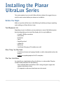
This section explains how to install a Planar UltraLux display. We suggest that you
read this entire section before you attempt an installation.
Before You Begin
Make sure you have all the items in the following lists before you begin unpacking
and installing your Planar UltraLux Series.
Tools/Equipment List
Depending on your installation, you may need one or more of the following items.
Note that depending on the size of the display, this list may be different.
•
•
•
•
•
•
•
•
#1 and # 2 Phillips screwdriver
Drill and bits
Nut drivers
Pencil
Digital/laser level
Ladders/lift
Back brace
Stud finder (if hanging LCD modules on a wall)
Other Things You May Need
• A 50-50 mix of water and isopropyl alcohol, as well as cheesecloth to clean the
displays.
• At least two capable people to lift LCDs into place.
Plan Your Installation
You should have a detailed plan of how the UltraLux is to be installed. The plan
should include calculations for the following:
• Floor/wall load. Make sure the floor/wall is strong enough to support the
weight of the UltraLux Series.
• AC receptacle in safe zone where boxes are to be stored.
Planar UltraLux Series Installation Guide
13
Powering On/Off Displays
Powering On/Off Displays
There are several ways to turn the UltraLux Series on or off:
•
•
•
•
14
Use the on/off switch on the AC power inlet
Use the power button on the remote control
Use the RS232 commands
Use the UltraLux Remote Monitoring embedded software via Ethernet
Planar UltraLux Series Installation Guide
Unpacking and Checking Accessories
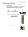
Unpacking and Checking Accessories
The UltraLux includes the LCD and an accessory kit. A wall mount kit can be
purchased separately.
Note: Screws should be no less than 1/4” in diameter. You will need a minimum of eight
screws for the top mounting bracket and a minimum of four for the bottom kickstand
bracket. Additional screws may be needed depending on your installation.
Accessory Kit
Part
Description
AC power cord
90 degree low profile power cord.
Remote control
Used to turn on/off displays, as well as
to navigate through on-screen menus.
Picture
Note: Batteries are included and
installed.
HDMI cable
USB drive
Contains the Planar UltraLux Series
Installation Guide.
Planar UltraLux Series Installation Guide
15
Unpacking and Checking Accessories
Optional Planar-Supplied Accessories
The following optional items are available to order as part of your installation:
• Pedestal
• Planar ContentSmartTM Media Player
• ProfileTM Wall Mount
16
Planar UltraLux Series Installation Guide
Wall Mounting LCD
Using Planar Profile
Mount
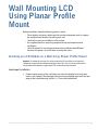
Before installation, keep the following points in mind:
• These displays are heavy. Make sure that you have adequate studs to support
the weight of each display if installing on a wall.
• The UltraLux must be installed on a flat surface.
• Use supplied UltraLux mounting template for top and bottom bracket
installation.
• The wall mounts for a landscape and portrait installation look different.
However, the process to install them is exactly the same.
Installing an LCD Module on a Wall Using Planar Profile Mount
Caution: For whatever structure is used to mount the LCD modules, be sure that it is
sufficiently engineered to handle the weight of the LCDs. Also be sure to purchase the
correct hardware needed to support the LCDs mounted to that structure.
Landscape Installation
1
Find the center point on the wall where you want the display to be hung and
mark it with a pencil. The top edge of the mounting template represents the top
edge of the installed display, which is 1.5” from the marked hole.
Planar UltraLux Series Installation Guide
17
Installing an LCD Module on a Wall Using Planar Profile Mount
18
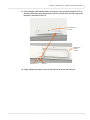
2
Using the Planar provided mounting template, line up the top hole in the
template with the center point on the wall. This is where the center of the top
bracket will be hung.
3
Screw in the appropriate hardware in the top middle hole of the template.
4
Let the template hang vertically, as the bottom hole in the template determines
where the bottom bracket will be installed.
5
Screw in the appropriate hardware in the bottom middle hole of the template.
6
Remove each screw and the template.
Planar UltraLux Series Installation Guide
Installing an LCD Module on a Wall Using Planar Profile Mount
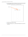
7
Line up the middle hole of the top wall bracket with the screw hole drilled from
the template.
Note: This picture shows brackets for a landscape installation.
8
Tighten the screw into the bracket.
9
Use a level to make sure the bracket is level.
10 Then install additional screws as needed.
11 Install the center screw in the bottom bracket and repeat steps 9-10.
Planar UltraLux Series Installation Guide
19
Installing an LCD Module on a Wall Using Planar Profile Mount
12 Using two people, carefully hang the back LCD onto the top wall mount bracket
using the square brackets on the back of the display.
Caution: Be sure that these are securely hung, as the top of the wall bracket will hold most of
the weight of the display.
Note: The pictures above show a landscape installation.
20
Planar UltraLux Series Installation Guide
Installing an LCD Module on a Wall Using Planar Profile Mount
13 On the bottom wall bracket, there is a latch pin. Once you have hung the LCD on
the top wall bracket, align the latch pin with the slot on the kickstand stop bracket
located on the back of the LCD.
Kickstand stop
bracket
Bottom wall
mount
bracket
Captive screw
Latch pin
14 Finger tighten the captive screw on the bottom to secure the latch pin.
Planar UltraLux Series Installation Guide
21
Installing an LCD Module on a Wall Using Planar Profile Mount
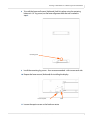
Portrait Installation
1
Find the top alignment hole on which the display will be hung by using the
alignment bar shipped with your display. Then mark that spot on the wall with a
pencil.
Determine the desired
position of the display on the
wall.
Place mark of centerline 1.5”
below the top edge of the display.
2
22
Place a mark on the centerline of the display, 1.5” below the top edge.
Planar UltraLux Series Installation Guide
Installing an LCD Module on a Wall Using Planar Profile Mount
3
With the alignment bar vertical (shipped with alignment brackets), locate the
lower alignment hole and then mark that spot with a pencil.
Hang alignment bar
from top hole.
Bottom of alignment bar
for Portrait installation
4
Hang the alignment bar from the top hole that you marked in the first step. Using
a 1/4” screw to lightly secure the alignment bar.
Planar UltraLux Series Installation Guide
23
Installing an LCD Module on a Wall Using Planar Profile Mount
5
To install the upper wall mount, hold the mount in place using the centering hole
in the middle of the mount and use a 1/4” lag screw to secure it.
Centering hole
24
6
Level the wall mount before continuing.
7
Install the remaining lag screws - eight are recommended but more can be used
as necessary.
Planar UltraLux Series Installation Guide
Installing an LCD Module on a Wall Using Planar Profile Mount
8
To install the lower wall mount (kickstand), hold it in place using the centering
hole and a 1/4” lag screw (use the lower alignment hole that was marked in
step 3.
Centering hole
9
Install the remaining lag screws - four are recommended - with two on each side.
10 Prepare the lower mount (kickstand) for installing the display.
Loosen captive.
Latch
11 Loosen the captive screw so the latch can rotate.
Planar UltraLux Series Installation Guide
25
Installing an LCD Module on a Wall Using Planar Profile Mount
12 Using two people, carefully hang the back LCD onto the top wall mount bracket
using the square brackets on the back of the display.
Note: This example shows a Landscape installation. The Portrait installation is similar.
Caution: Be sure that these are securely hung, as the top of the wall bracket will hold most of
the weight of the display.
26
Planar UltraLux Series Installation Guide
Installing an LCD Module on a Wall Using Planar Profile Mount
13 On the bottom wall bracket, there is a latch pin. Once you have hung the LCD on
the top wall bracket, align the latch pin with the slot on the kickstand stop bracket
located on the back of the LCD.
Kickstand stop
bracket
Bottom wall
mount
bracket
Captive screw
Latch pin
14 Finger tighten the captive screw on the bottom to secure the latch pin.
Planar UltraLux Series Installation Guide
27
Installing an LCD Module on a Wall Using Planar Profile Mount
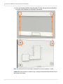
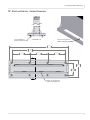
Installing Cables
The only cable you will need to install is the AC power cord into the back of the
control module. Depending on your setup, you may need additional cables for media
player integration, as well as for sending RS232 commands. Below are examples of
cable connections between the control module and a media player.
Shown with media player cover on
Shown with media player cover removed
28
Planar UltraLux Series Installation Guide
USB and Power Hook-Up
Touchscreen Setup
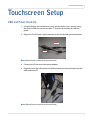
USB and Power Hook-Up
1
Using the display service kickstand, swing out the display. If you are only using
the mount, make sure you have at least 1” clearance to connect the USB and
power.
2
Plug in the 5V, 4A Power supply connector to the touchscreen power connector.
Power
USB
Note: USB and Power connection to the touchscreen.
3
Connect the 5V line cord to the power adapter.
4
Plug one end of the USB cable to the USB connector on the touchscreen and the
other end to the PC.
Note: USB and Power connection to the touchscreen.
Planar UltraLux Series Installation Guide
29
Touchscreen MultiTouch Driver Installation
Touchscreen MultiTouch Driver Installation
1
With the PC on, plug in the USB memory stick to the USB drive.
2
Locate and open the USB drive.
3
Double-click on the “mt_driver_kitV4.1212RC2” to install the driver.
4
Follow installation prompts until driver installation is complete.
Once driver installation is complete, the touchscreen is ready for use.
Touchscreen (PQLabs) MultiTouch Platform Content
The PQLabs Software is used for troubleshooting and calibration. The different
menus are described below.
1
On the PC, select the Start menu, All Programs and then PQLabs Software.
2
Click on “MultiTouch Platform” to open the PQLabs MultiTouch Platform window.
Touchscreen Information
• Serial Number – Displays the serial number of the connected touchscreen.
• Firmware Version – Displays the firmware version of the touchscreen selected
under the “Serial Number” dropdown menu.
• Touch Points – Displays the number of touch points for which the touchscreen
is capable.
• Status – Displays the current status of the touchscreen.
Calibration
• Calibration – Starts a 4-point calibration of the touchscreen. Perform the
programmed touchscreen calibration process. At the conclusion of the
calibration routine your touchscreen device is ready to use and will perform
with accurately positioned touch points.
• Reset Calibration – Resets calibration to factory default settings.
Utility
• Diagnose – Starts the “MultiTouchDoctor” program. This can be used to
troubleshoot issues with the touchscreen.
30
Planar UltraLux Series Installation Guide
Uninstalling the MultiTouch Driver
Options
• Default settings on options have the following programs enabled: Tuio
Support, Flash Tuio Support, Handwriting Optimization, Enable Windows
Native Touch, Enable Mouse/Keyboard Simulation, and Launch When Windows
Starts Up.
• Flexible Scan Rate is at a default setting.
Uninstalling the MultiTouch Driver
1
On the PC, select the Start menu, All Programs and then PQLabs Software.
2
Click on the MultiTouch Driver.
3
Select the Uninstall option.
Planar UltraLux Series Installation Guide
31
Uninstalling the MultiTouch Driver
32
Planar UltraLux Series Installation Guide
External Control and
Monitoring
In addition to using the UltraLux remote control and display, there are other methods
of controlling the UltraLux externally:
• Using a serial (RS232) link to send commands and to receive responses to those
commands.
• Using SNMP (Simple Network Management Protocol) to monitor the device
status.
• Using Remote Monitoring software via a web browser.
Planar UltraLux Series Installation Guide
33
RS232 Communication
RS232 Communication
RS232 control is not necessary for operation, but is a convenient way to control
displays from a computer at a distance. If your installation will not use RS232 control,
skip this section. Most things you can do with the remote, you can do with RS232
commands. Plus, you can send inquiries to the displays and find out the current
settings and values. RS232 connections are made with standard straight-through
cables.
Connecting the RS232 Cable
The RS232 cable will connect either to a PC or a media player, depending on your
setup.
34
Planar UltraLux Series Installation Guide
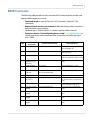
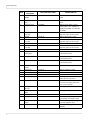
RS232 Commands
RS232 Commands
The following table provides the most common RS232 commands that can be used.
Keep the following points in mind:
• Command length: 8 bytes (64 bits) for "Set" Commands, 4 bytes for "Get"
Commands
• Required check sum for each command: 100h (the last byte value is chosen to
force the check sum to 100 hex)
• The baud rate is 19200 (8 data bit, 1 stop bit, no parity, no flow control)
• Example in hex for "Set Backlight Brightness to 80": 08 22 00 00 00 00 50 86
(where green bytes are the command, blue is the value, red makes the check
sum = 100h)
Item
Command
Description
Command Value in Hex
Command Result
1
Set Power to "off"
08 22 FE 00 00 00 00 D8
Video board in soft power off
mode; backlight off
2
Set Power to "on"
08 22 FD 00 00 00 00 D9
Video board on; backlight on if
video is present
3
Get Power Status
04 21 16 C5
Returns "Power: ON" if on; "Power:"
if off'; Power: OFF if on but no video
4
Set Backlight
Brightness to "X"
(0 to 100)
Get BL Brightness
Set to 80: 08 22 00 00 00 00 50 86
Brightness set to commanded
value
04 21 08 D3
Returns “Brightness = value”
6
Set Contrast to "X"
(0 to 100)
Set to 40:
08 22 01 00 00 00 28 AD
Contrast set to commanded value
7
Get Contrast
04 21 09 D2
Returns “Contrast = value”
8
Set Sharpness to
"X" (-4 to 4)
Set to -4: 08 22 03 00 00 00 00 D3
9
Get Sharpness
04 21 0A D1
10
Set Color Temp to
"4200K"
08 22 04 00 00 00 02 D0
Sharpness set as commanded
(for -4 a value of 0 is used; for 4, 8 is
used)
Returns "Sharpness = value" where
value is Sharpness setting + 4
Color temp set to commanded
value
11
Set Color Temp to
"5000K"
08 22 04 00 00 00 03 CF
Color temp set to commanded
value
12
Set Color Temp to
"6500K"
08 22 04 00 00 00 04 CE
Color temp set to commanded
value
13
Set Color Temp to
"7500K"
08 22 04 00 00 00 05 CD
Color temp set to commanded
value
5
Planar UltraLux Series Installation Guide
35
RS232 Commands
Item
Command Value in Hex
Command Result
14
Set Color Temp to
"9300K"
08 22 04 00 00 00 06 CC
Color temp set to commanded
value
15
Set Color Temp to
"user"
08 22 04 00 00 00 07 CB
Color temp set to commanded
value
16
Get Color Temp
04 21 0B D0
17
Set Red to "X"
(0 to 100)
Set to 50: 08 22 0E 00 00 00 32 96
Returns "Color Temp = value"
where value is 2 for 4200K, 3 for
5000K, 4 for 6500K, 5 for 7500K, 6
for 9300K
Red set to commanded value
(impacts only user color mode)
18
Get Red
04 21 0C CF
Returns “Red Color = value”
19
Set Green to "X"
(0 to 100)
Get Green
Set to 20: 08 22 0F 00 00 00 14 B3
Green set to commanded value
(impacts only user color mode)
Returns “Green Color = value”
Set Blue to "X"
(0 to 100)
Get Blue
Set to 80: 08 22 10 00 00 00 50 76
23
Set Input to
"DisplayPort"
08 22 02 00 00 00 00 D4
The default source becomes the
commanded source
24
Set Input to "HDMI" 08 22 05 00 00 00 00 D1
The default source becomes the
commanded source
25
Set Input to "VGA"
08 22 06 00 00 00 00 D0
The default source becomes the
commanded source
26
Set Volume to "X"
(0-100)
Set to 100: 08 22 09 00 00 00 64 69
Volume set to commanded volume
27
Get Volume
04 21 0F CC
Returns “Volume = value”
28
Set Mute to "on"
08 22 0A 00 00 00 01 CB
Activates mute
29
Set Mute to "off"
08 22 0A 00 00 00 00 CC
Deactivates mute
30
Get Mute
04 21 14 C7
31
Get Input Status
04 21 07 D4
32
08 22 12 00 00 00 00 C4
08 22 13 00 00 00 02 C1
Color space set to sRGB
34
Set Color Space to
full color
Set Color space to
SRGB
Get Color Space
Returns "Mute = value" where 0 is
mute off and 1 is mute on
Returns "HDMI", "VGA", or "DPRx" (if
no source is present, returns the
last source searched)
Color space set to full color
04 21 15 C6
Returns “Color Space = value”
35
Do Auto Adjust
08 22 07 00 00 00 00 CF
36
Do Auto Color
Adjust
Do a Reset
08 22 08 00 00 00 00 CE
If VGA source is present, a
sync/timing auto adjust is done
If VGA source is present, a gray
level auto adjust is done
Restores all settings to factory
defaults
20
21
22
33
37
36
Command
Description
04 21 0D CE
04 21 0E CD
08 22 11 00 00 00 00 C5
Planar UltraLux Series Installation Guide
Blue set to commanded value
(impacts only user color mode)
Returns “Blue Color = value”
SNMP Monitoring
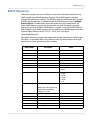
SNMP Monitoring
The current settings and status of UltraLux units can be remotely monitored using
SNMP (Simple Network Management Protocol), if the SNMP option is enabled
through the web browser settings. The MIB (Management Information Base) used for
all Planar display products is available by electronic distribution in the file PLANARDISPLAY-MIB.txt. The table below shows the objects that can be monitored – all
Planar SNMP objects are read-only, and no traps are used. The default read-only
community string for all Planar SNMP objects is “public”. Once the PLANAR-DISPLAYMIB is loaded in your SNMP manager, you can walk all the available objects from the
top-level object PlanarSystems(1.3.6.1.4.1.19125) or its sub-object
PlanarDisplayProduct(1).
Most object values are integer type, except where noted. Generally, for integer types,
the value -1 is returned if there is any internal system or communication error, and
normal return values are zero or positive integers.
Object Name
Description
Value
plnrModel
Model name (string)
UltraLux
plnrInputSelect
User-selected input source
1 = HDMI, 2 = DisplayPort, 3 = VGA
plnrInputStatus
Input source status
0 = Source Absent, 1 = Source Present
plnrDisplayBacklight
Backlight on/off state
1 = On, 0 = Off
plnrDisplayBrightness
User-selected brightness value
0-100
plnrDisplayContrast
User-selected contrast value
0-100
plnrDisplaySharpness
User-selected sharpness value
0-8
plnrDisplayColorSpace
User-selected color space
0 = full color
2 = sRGB
plnrDisplayColorTemp
User-selected color temperature
2 = 4200K
3 = 5000K
4 = 6500K
5 = 7500K
6 = 9300K
7 = user
plnrDisplayGainRed
User-selected red gain value
0-100
Note: Gain values apply only
when color temperature
setting is 7 or user.
plnrDisplayGainGreen
User-selected green gain value
0-100
plnrDisplayGainBlue
User-selected blue gain value
0-100
plnrAudioVolume
User-selected volume setting
0-100
plnrAudioMute
User-selected audio mute
1 = On, 0 = Off
plnrPower1
Power supply #1 status
1 = OK, 0 = Failed
plnrPower2
Power supply #2 status
1 = OK, 0 = Failed
Planar UltraLux Series Installation Guide
37
Sending RS232 Commands Via UDP
Sending RS232 Commands Via UDP
The UDP port 57 accepts the same command sets as RS232. It is convenient for IP
control applications and can be tested with a UDP terminal program such as the
Hercules SETUP utility available from www.HW-group.com
Note: Ensure that the Enable ASCII command service (UDP port 57) box is checked on the
Access Control page of the Remote Monitoring software.
Notice the following in the example below:
• The Module IP address must match the Planar device server’s IP address
• Enter 57 in the Port box.
• “04 21 16 C5” in the Send box corresponds to the Get Power Status RS232
command.
38
Planar UltraLux Series Installation Guide
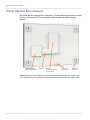
Using WallNet Assistant
Using WallNet Assistant
WallNet Assistant is a software program that finds Planar hardware on a network. This
will help you find the IP address needed to access the Remote Monitoring functions.
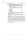
1
WallNet Assistant is distributed as Planar_WallNet_Assistant_(version).zip. Extract
all files to a new folder in your "Program Files" folder (or another convenient
location).
2
Double-click "WallNet Assistant.exe" to launch Planar WallNet Assistant. If any
error messages appear, then download and install (or update) Microsoft .NET
Framework version 2.0, and then try launching "WallNet Assistant.exe" again.
Planar UltraLux Series Installation Guide
39
Using WallNet Assistant
3
When WallNet Assistant starts, it looks for all Planar device servers on the network
and lists them in the window.
• Each Planar device found on the local network is listed with its name, IP
address, date and time.
• New device servers just out of the box are listed with default names. The date
and time shown are from the device’s own clock. Both of these can be
changed later.
• WallNet Assistant uses a very simple broadcast protocol to discover Planar
device servers on the local network. Most networks do not route broadcast
packets, so it is very possible to have properly configured, reachable devices
on your network that WallNet Assistant won’t find. Consult with your network
administrator if you are having trouble using WallNet Assistant to find Planar
devices. Also see the information about the Route Add Command at the end
of this section if you are trying to find a device at the factory static IP address.
4
40
You can double-click any Planar device server in the list to open your default
browser pointed at that device.
Planar UltraLux Series Installation Guide
Using WallNet Assistant
5
When your browser connects to a Planar network device, you should see a page
similar to the following.
Planar UltraLux Series Installation Guide
41
Using WallNet Assistant
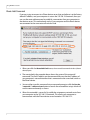
Route Add Command
If you are trying to connect to a Planar device server that you believe is at the factory
default IP address, and your computer is not on the 192.168.12.0 network, then you
can use the route add command to establish a connection from your computer to
that device server. This method only works if your computer and the Planar device
are connected to the same network switch or hub.
1
When you click the Route Add Cmd button, the route add command window (shown
above) opens.
2
The area circled in the example above shows the syntax of the route add
command. The final IP address on the command line must be the IP address of
your computer’s network interface that is connected to the same hub/switch as
the Planar device.
3
You can either type this command into a command prompt or click the Run the
“route add...” command now button to launch the routeadd.bat script, which will
run the command exactly as shown.
4
42
When the route add is successful, it establishes a temporary network route from
your computer to the 192.168.12.0 network. This allows your computer to
communicate with the Planar device server located at 192.168.12.12.
Planar UltraLux Series Installation Guide
Planar UltraLux Remote Monitoring
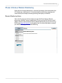
Planar UltraLux Remote Monitoring
Planar UltraLux Remote Monitoring is software that displays information about the
LCD display via a web browser. It is used primarily for monitoring, reporting and
some control (for example, manually powering the displays on and off).
Remote Monitoring Home
This is the first page you will see when you open the Planar UltraLux Remote
Monitoring software. Launch a web browser. If you are using DHCP, enter in the IP
address shown on the Info tab of UltraLux Remote Monitoring. If you are not using
DHCP, enter http://192.168.12.12 in the address bar. For either web address entered,
you should see a page similar to the following.
Planar UltraLux Series Installation Guide
43
Planar UltraLux Remote Monitoring
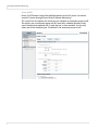
Unit Status
The Unit Status page shows a list of the different system settings for the LCD. It also
shows whether or not the two power supplies contained in the control module are
on or off.
44
Planar UltraLux Series Installation Guide
Planar UltraLux Remote Monitoring
Display Control
The Display Control page contains two sub-pages: Power On/Off and Custom
Commands Setup. These are described in the following pages.
Planar UltraLux Series Installation Guide
45
Planar UltraLux Remote Monitoring
Power On/Off
Power On/Off buttons control the backlight power, not the AC power. You cannot
control AC power through Planar UltraLux Remote Monitoring.
This section has four options for which you can schedule an automatic power on/off.
The options are: no automatic power on/off, same daily schedule, Monday-Friday
same schedule and weekends off. Or each day has its own schedule. You can only
select one of the schedule types. The default is No automatic power on/off.
46
Planar UltraLux Series Installation Guide
Planar UltraLux Remote Monitoring
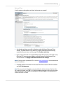
Custom Commands Setup
The Custom Commands Setup page allows you to establish what the ten Custom
Command buttons will do.
1
Type a label for the button in Button 1 Text.
2
In ASCII Command(s), enter a binary protocol such as hex commands. An
example is shown above.
3
Click Test button 1 commands to send the commands immediately. You will see
an output page showing the commands sent and replies received (if any). Use the
browser’s Back button to return from this results page to avoid losing unsaved
changes. If you select the Custom Commands Setup page again, you will lose
unsaved changes.
4
Scroll to the bottom of the Custom Commands Setup page and click Change
Custom Command Buttons. This applies what you have done to the custom
buttons accessed from Custom Commands Setup at the top of the left menu.
Note: It is suggested that you only send one command at a time. If you want to send
additional commands, repeat the steps in this section.
Planar UltraLux Series Installation Guide
47
Planar UltraLux Remote Monitoring
Admin Setup
The Admin Setup page contains three sub-pages: Network Setup, Time and Date,
Access Control and Software Update. These are described in the following pages.
48
Planar UltraLux Series Installation Guide
Planar UltraLux Remote Monitoring
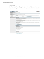
Network Setup
This page allows you to configure network settings and whether or not you use
DHCP.
1
In the Hostname box it now says Planar. Change this name to something more
appropriate. This will be the name for this particular server. The hostname is
limited to 16 characters: alphanumeric, dash, or underscore only.
2
If you want to enter a domain name for server name lookups, type it in the
Domain name box.
3
Do one of the following:
• If you will use DHCP, go to step 4.
• If you will not use DHSCP, go to step 5.
4
Under the DHCP section, choose Yes, use DHCP.
a Change the default DHCP timeout (ten seconds) only if instructed by your
network administrator.
Planar UltraLux Series Installation Guide
49
Planar UltraLux Remote Monitoring
b You do no need to fill in anything under the Static (non-DHCP) Network
Settings section. However, if you do, these settings will be used in the event
that the DHCP attempts to time out.
c Go to step 6.
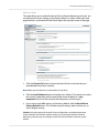
5
Under the DHCP section, choose No, use static settings.
a In the Static (non-DHCP) Network Settings section, enter the IP address given
to you by the network administrator.
b Enter the Network mask, DNS server(s), and Gateway as instructed by the
network administrator.
c Go to step 6.
6
Scroll to the bottom of the page and click Confirm and apply new network
settings to receive the Confirm Network Change page.
7
Review the settings to make sure they are correct. Click OK, apply changes now
to receive the Applying Network Changes page. This shows the network settings
to be used.
Note: If you have changed the static IP address or changed from static to DHCP setup, you
may need to point your browser at the new address.
8
50
You may have to click the Refresh button on your browser to see the new name
in the upper left corner of the page.
Planar UltraLux Series Installation Guide
Planar UltraLux Remote Monitoring
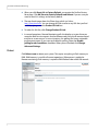
Date and Time
Use this page to change date and time information as needed.
1
Set the date and time manually in the box under the Manual Date and Time
section. The date format is very exact. Fill in the current date and time using
exactly the format shown on the page. Click Set date and time.
2
If you want to have the server periodically check the time from a network source,
fill in the NTP server name or address, and poll interval in the Date and Time
Server section. Click Apply new date and time server settings.
Note: If you don’t have a preferred NTP server, then www. pool.ntp.org is a reasonable choice
for most installations.
3
Carefully read the instructions in the Local Time Zone section. Fill in the text box
and click Set time zone.
Note: The start and end of daylight saving time default to the first Sunday of April and the
last Sunday of October. As of 2007, U.S. locales that observe daylight saving time must enter
start and end dates in this section. For example, EST5EDT,M3.2.0,M11.1.0 is correct for U.S.
Eastern time zone as of 2007.
Planar UltraLux Series Installation Guide
51
Planar UltraLux Remote Monitoring
Access Control
The Access Control page allows you to set parameters needed to access the web, the
Remote Monitoring network, RS232 commands, as well as select the correct baud
rate.
52
Planar UltraLux Series Installation Guide
Planar UltraLux Remote Monitoring
Software Setup
This page allows you to upload the latest UltraLux Remote Monitoring software. You
can also reset all of your settings to the factory defaults, as well as choose the web
page link that is associated with the Planar logo in the top right corner of the page.
1
Click the Choose File button to locate the latest UltraLux software that you
downloaded from Planar’s website.
Note: Make sure the software is downloaded to a local drive.
2
Click the Load Software button to load the new software. This process can take a
few minutes, depending on the speed of the network update. It is very
important that you do not interrupt the load process once it begins.
3
If you want to reset ALL settings to the factory default, click the Reset ALL to
Factory Default button. This includes network settings, date and time, etc., as
well as display settings.
Caution: Using this option will reset all of your configurations and reboot the remote
monitor. Because this includes network settings, be aware that the UltraLux Remote
Monitoring software may not configure to the same network address after the system
reboots.
Planar UltraLux Series Installation Guide
53
Planar UltraLux Remote Monitoring
4
When you click Reset ALL to Factory Default, you receive the Confirm Factory
Reset page. Click OK, Reset to Factory Defaults and Reboot if you are sure you
want to reset ALL settings to the factory default.
5
The top of each page shows the Planar logo, which is a link to
http://www.planar.com. You can change this link to refer to any URL that you find
useful by typing it into the Product ID Link box.
6
To make this link live, click Change Product ID Link.
7
In normal operations, Remote Monitoring polls the displays at a rate of one per
second to look for user requests that have been made using the IR remote control
and the on-screen menus. In some situations, this polling can have a noticeable
performance impact. If you want to disable this polling, select the Disable
polling for alert conditions checkbox. When you are finished, click Change
Advanced Settings.
Reboot
Click Reboot now to reboot your system. This copies everything in flash memory to
RAM. RAM memory is used for all current operations. When power is applied to
Remote monitoring, flash memory is copied to RAM. Reboot takes about 90 seconds.
54
Planar UltraLux Series Installation Guide
On-Screen Display Menus
On-Screen Display Menus
On-screen menus can be accessed using the remote control. These menus allow you
to adjust image brightness, contrast, sharpness, color, sound, and various System
Settings. Below are pictures of the menus and a menu tree that shows the options on
each menu.
Image Menu
Planar UltraLux Series Installation Guide
55
On-Screen Display Menus
Image
Brightness
Contrast
Sharpness
auto
Color
Color temp
4200K
5000K
6500K
7500K
9300K
user
Full color
srgb
Hue
Saturation
56
Planar UltraLux Series Installation Guide
Red
Green
Blue
xvycc
On-Screen Display Menus
Display Menu
Display
Auto adjust
phase
clock
Display position
Move position V
Move position H
Planar UltraLux Series Installation Guide
57
On-Screen Display Menus
Sound Menu
Sound
volume
mute
58
Planar UltraLux Series Installation Guide
On-Screen Display Menus
System Menu
Planar UltraLux Series Installation Guide
59
On-Screen Display Menus
system
Input
Display Port
VGA
DVI/HDMI
Osd Settings
Timer
3 sec
6 sec
12 sec
Rotation
0°
90°
180°
270°
Position
Transparency
Language
English
Espanol
Deutsch
French
Reset
60
Planar UltraLux Series Installation Guide
Specifications
Screen Active Area
Size
Power Consumption
(typical)
Dimensions
(including mount)
Bezel Width
Weight
Mounting
UltraLux 70”
UltraLux 80”
UltraLux 70” Touch
UltraLux 80” Touch
70 inch
80 inch
70 inch
80 inch
300W
350W
300W
350W
62.2" x 36.2" x 3.0"
72.2" x 41.7" x 2.8"
62.5” x 36.4” x 3.4”
73.5” x 43.1” x 3.4”
(1581mm x 920mm x 77mm) (1835mm x 1060mm x 71mm) (1588mm x 926mm x 85mm) (1868mm x 1096mm x 85mm)
1.1” (27mm)
1.3” (32mm)
Standard: 133 lbs (60 kg)
With ERO: 172 lbs (78 kg)
Standard: 174 lbs (79 kg)
With ERO: 221 lbs (100 kg)
179 lbs (81 kg)
243 lbs (110 kg)
Planar Profile mounting or
VESA: 400x400; 4 holes
Planar Profile mounting or
VESA: 600x800; 4 holes
Planar Profile mounting or
VESA: 400x400; 4 holes
Planar Profile mounting or
VESA: 600x800; 4 holes
Orientation
1.1” (27mm)
Portrait/Landscape
Recommended
Usage
24/7
Aspect Ratio
16:9
Brightness (typical)
700 nits
Backlight
Edge-lit LED
Contrast Ratio
(typical)
5000:1
Response Time
(typical)
4 ms
Frame Rate
120 Hz
Viewing Angle
176° H,V
Native Resolution
FHD 1920 x 1080 (1080p)
Display Colors
Surface Treatment
1.9” (48mm)
> 1 billion, full 10-bit data path
TM
Optional ERO
EROTM Optically Bonded Glass
Optically Bonded Glass
Control and
Monitoring
RS232/LAN with SNMP
Line Voltage
Universal 120/240V, 50/60Hz
External
Connections
HDMI, DisplayPort, VGA, AC Power IEC C14
Operating
Temperature
32°F to + 104°F (0°C to + 40°C)
Storage
Temperature
-4°F to + 140°F (-20°C to + 60°C)
Humidity
20 to 90% RH
Approvals
FCC Class A, EN60950, CE
Options
Landscape wall mount, Portrait wall mount, White or black edge trim
Single-sided pedestal, Double-sided pedestal, 6-point multi-touch
Warranty
3 Years Advanced Exchange
Planar UltraLux Series Installation Guide
61
Signal Compatibility
Signal Compatibility
The UltraLux Series supports the following factory preset modes:
62
Mode
Resolution
Refresh
Rate
Horizontal
Frequency
Pixel
Frequency
VGA
640 x 480
60 Hz
31.5 kHz
25.157 MHz
SVGA
800 x 600
56 Hz
35.2 kHz
36 MHz
SVGA
800 x 600
60 Hz
37.9 kHz
40 MHz
XGA
1024 x 768
60 Hz
48.4 kHz
65 MHz
WXGA
1280 x 720
60 Hz
45 kHz
74.25 MHz
SXGA
1280 x 1024
60 Hz
64 kHz
108 MHz
UXGA
1600 x 1200
60 Hz
75 kHz
162 MHz
WUXGA
1920 x 1080
50 Hz
56.25 kHz
148.5 MHz
WUXGA
1920 x 1080
60 Hz
67.5 kHz
148.5 MHz
Planar UltraLux Series Installation Guide
UltraLux Dimensions
Note: All Drawings for the UltraLux Series have the same dimensions in Portrait mode.
Simply flip the drawings around to see the correct dimensions.
70” LCD Module Dimensions
70” LCD Front View - Landscape
Planar UltraLux Series Installation Guide
63
70” LCD Module Dimensions
70” LCD Rear View - Landscape
00RXQW3RLQWVPP[PP
&$%/(&29(5$1',2/2&$7,21
0(',$3/$<(5&203$570(17
64
Planar UltraLux Series Installation Guide
70” LCD Module Dimensions
70” LCD Side View - Landscape
3DQHO3URILOH
2YHUDOO
Planar UltraLux Series Installation Guide
65
70” LCD Module Dimensions
70” Panel Mounting Dimensions
LQ
PP
09(6$0RXQW
LQ
PP
7RHGJHRISDQHO
LQ
PP
7RHGJHRISDQHO
[3ODQDU
0RXQW%UDFNHW
LQ
PP
7RHGJHRISDQHO
LQ
PP
7RHGJHRISDQHO
LQ
PP
7RHGJHRISDQHO
LQ
PP
7RHGJHRISDQHO
3RZHU%R[
&RPSDUWPHQW
0HGLD3OD\HU
&RPSDUWPHQW
LQ
PP
7RHGJHRISDQHO
LQ
PP
09(6$0RXQW
&DEOH&RYHU
DQG,2/RFDWLRQ
LQ
PP
7RHGJHRISDQHO
LQ
PP
7RHGJHRISDQHO
LQ
PP
7RHGJHRISDQHO
66
Planar UltraLux Series Installation Guide
70” LCD Module Dimensions
70” Wall Mount Kit - Front Landscape
7<3
; ',63/$<287/,1(
)52179,(:
70” Wall Mount Kit - Side Landscape
',63/$<
287/,1(
'(9,(:
Planar UltraLux Series Installation Guide
:$//2502817,1*685)$&(
67
70” LCD Module Dimensions
70” Wall Mount Kit - Front Portrait
7<3
7<3 ; ',63/$<287/,1(
68
Planar UltraLux Series Installation Guide
70” LCD Module Dimensions
70” Wall Mount Kit - Side Portrait
',63/$<
287/,1(
:$//2502817,1*685)$&(
,'(9,(:
Planar UltraLux Series Installation Guide
69
70” LCD Module Dimensions
70” LCD Touch View - Front
LQ
PP%H]HO
LQ
PP
LQ
PP
70
Planar UltraLux Series Installation Guide
LQ
PP
%H]HO
70” LCD Module Dimensions
70” LCD Touch View - Rear
LQ
PP2YHUKDQJRQ
WRSDQGERWWRP
DOGHSWKRIXQLW
LQ
PP
2YHUKDQJRQOHIWDQGULJKWVLGH
(OHF&RQWURO
0RGXOH
$
&DEOH&RYHU
0HGLD3OD\HU
&RPSDUWPHQW
3/$1$56<67(
1:&203
Planar UltraLux Series Installation Guide
71
70” LCD Module Dimensions
70” LCD Touch View - Side
LQ
PP7RWDOGHSWKRIXQLW
2YHUKDQJRQO
72
Planar UltraLux Series Installation Guide
%
80” LCD Module Dimensions
80” LCD Module Dimensions
80” LCD Front View - Landscape
Planar UltraLux Series Installation Guide
73
80” LCD Module Dimensions
80” LCD Rear View - Landscape
00RXQW3RLQWVPP[PP
&$%/(&29(5$1',2/2&$7,21
0(',$3/$<(5&203$570(17
74
Planar UltraLux Series Installation Guide
80” LCD Module Dimensions
80” LCD Side View - Landscape
3DQHO3URILOH
2YHUDOO
Planar UltraLux Series Installation Guide
75
80” LCD Module Dimensions
80” Panel Mounting Dimensions
LQ
PP
09(6$0RXQW
[3ODQDU0RXQW%UDFNHW
LQ
PP
7RHGJHRISDQHO
LQ
PP
7RHGJHRISDQHO
LQ
PP
7RHGJHRISDQHO
LQ
PP
7RHGJHRISDQHO
LQ
PP
7RHGJHRISDQHO
LQ
PP
7RHGJHRISDQHO
3RZHU%R[
&RPSDUWPHQW
0HGLD3OD\HU
&RPSDUWPHQW
LQ
PP
09(6$0RXQW
&DEOH&RYHU
DQG,2/RFDWLRQ
LQ
PP
7RHGJHRISDQHO
LQ
PP
7RHGJHRISDQHO
LQ
PP
7RHGJHRISDQHO
76
Planar UltraLux Series Installation Guide
80” LCD Module Dimensions
80” Wall Mount Kit - Front Landscape
7<3
7<3 7<3 ',6
28
; ',63/$<287/,1(
; )5217 9,(:
80” Wall Mount Kit - Side Landscape
:$//2502817,1*685)$&(
',63/$<
287/,1(
6
Planar UltraLux Series Installation Guide
77
80” LCD Module Dimensions
80” Wall Mount Kit - Front Portrait
7<3
7<3 ',63/
287/
; ',63/$<287/,1(
78
; Planar UltraLux Series Installation Guide
6,'(
80” LCD Module Dimensions
80” Wall Mount Kit - Side Portrait
',63/$<
287/,1(
:$//2502817,1*685)$&(
6,'(9,(:
Planar UltraLux Series Installation Guide
79
80” LCD Module Dimensions
80” LCD Touch View - Front
LQ
PP
%H]HO
'(7$,/%
6&$/(
LQ
PP
LQ
PP%H]HO
80
Planar UltraLux Series Installation Guide
LQ
PP
80” LCD Module Dimensions
80” LCD Touch View - Rear
[UHPRYDEOHFRUQHU
EUDFNHWIRU7RXFK)UDPH
LQVWDOODWLRQVHUYLFDELOLW\
LQ
PP
2YHUKDQJRQWRS
DQGERWWRPHGJH
LQ
PP
2YHUKDQJRQOHIW
DQGULJKWHGJH
(OHF&RQWURO
0RGXOH
$
&DEOH&RYHU
0HGLD3OD\HU
&RPSDUWPHQW
Planar UltraLux Series Installation Guide
3/$1$56<67(06
1:&203721
%($9(5721 25 81
80” LCD Module Dimensions
80” LCD Touch View - Side
LQ
PP
7RWDOGHSWKRIGLVSOD\
ZLWKWRXFK6ROXWLRQ
82
Planar UltraLux Series Installation Guide
%
Media Compartment Player Dimensions
Media Compartment Player Dimensions
LQ
PP
LQ
PP
'(7$,/$0HGLD3OD\HU&RPSDUWPHQW0D[8KHLJKW
6KRZQZLWKFRYHUUHPRYHG
$
9(6$PRXQW[
0HGLD3OD\HU&RPSDUWPHQW
,2/RFDWLRQ
Planar UltraLux Series Installation Guide
3/$
%(
83
Media Compartment Player Dimensions
84
Planar UltraLux Series Installation Guide
UltraLux Pedestals
The following picture shows examples of the 70” and 80” UltraLux pedestals.
Installing the UltraLux on the Pedestal Mount
The pedestal mount comes fully assembled, single or double-sided, depending on
your configuration. If you have ordered a single-sided pedestal mount, a back panel
will also be installed.
Caution: When installing the pedestal mount, you must ensure that it is attached to a
structure that safely supports UltraLux display.
Note: You must provide your own anchoring hardware to secure the pedestal mount.
1
Find the location on the floor where you will install the pedestal mount.
2
Remove both bottom trim pieces, which gives you access to the anchor points.
3
Find the set anchor points on the bottom of the pedestal (See "70” UltraLux
Pedestal - Anchor Dimensions" on page 89 and "80” UltraLux Pedestal - Anchor
Dimensions" on page 92.)
4
Depending on the surface to which you are anchoring, install the appropriate
hardware to secure the pedestal mount.
Planar UltraLux Series Installation Guide
85
Installing the UltraLux on the Pedestal Mount
86
5
Route all cabling through the bottom of the pedestal mount or through both
sides of the mount. If you run cables through the sides of the mount, you can
punch out holes and install grommets through which to run the cables.
6
Install the UltraLux on the Planar Profile Mount that is already attached to the
pedestal mount. See "Installing an LCD Module on a Wall Using Planar Profile
Mount" on page 17 for more information.
7
See the following pages for detailed drawings of the pedestal mounts, anchor
points, etc.
Planar UltraLux Series Installation Guide
70” UltraLux Pedestal Dimensions
70” UltraLux Pedestal Dimensions
70” UltraLux Pedestal - Front
LQ
PP
LQ
PP
LQ
PP
&HQWHURIGLVSOD\
LQ
PP
%RWWRPRIGLVSOD\
Planar UltraLux Series Installation Guide
87
70” UltraLux Pedestal Dimensions
70” UltraLux Pedestal - Top and Side
LQ
PP
LQ
PP
LQ
PP
[5HPRYDEOH%DVH&RYHUIRU
,QVWDOODQG&DEOH0DQDJHPHQW
,QVWDOOHG3RVLWLRQ
88
Planar UltraLux Series Installation Guide
70” UltraLux Pedestal Dimensions
70” UltraLux Pedestal - Anchor Dimensions
+DUGZDUHWR
DQFKRUSHGHVWDO
6(&7,21$$
2SHQWRWKHIORRUIRU
FDEOHPDQDJHPHQW
LQ
PP
LQ
PP
LQ
PP
LQ
PP
LQ
PP
$
LQ
PP
LQ
PP
$
2SHQWRWKHIORRUIRU
FDEOHPDQDJHPHQW
Planar UltraLux Series Installation Guide
89
80” UltraLux Pedestal Dimensions
80” UltraLux Pedestal Dimensions
80” UltraLux Pedestal - Front
LQ
PP
LQ
PP
LQ
PP
&HQWHURIGLVSOD\
LQ
PP
%RWWRPRIGLVSOD\
90
Planar UltraLux Series Installation Guide
80” UltraLux Pedestal Dimensions
80” UltraLux Pedestal - Top and Side
LQ
PP
LQ
PP
LQ
PP
[5HPRYDEOH%DVH&RYHUIRU
,QVWDOODQG&DEOH0DQDJHPHQW
,QVWDOOHG3RVLWLRQ
Planar UltraLux Series Installation Guide
91
80” UltraLux Pedestal Dimensions
80” UltraLux Pedestal - Anchor Dimensions
+DUGZDUHWR
DQFKRUSHGHVWDO
2SHQWRWKHIORRUIRU
FDEOHPDQDJHPHQW
6(&7,21$$
LQ
PP
LQ
PP
LQ
PP
LQ
PP
LQ
PP
$
LQ
PP
LQ
PP
$
2SHQWRWKHIORRUIRU
FDEOHPDQDJHPHQW
92
Planar UltraLux Series Installation Guide
Accessing Planar’s
Technical Support
Website
1
Go to http://partners.planarcontrolroom.com
2
Once you enter your login and password, you can access downloadable utility software,
new firmware, user manuals, and service manuals.
Downloading Additional Documentation and Software
Some of the other documents and software updates for the for the UltraLux Series are or will
be available from the Technical Support Department website.
Downloading Utility Software
1
Go to http://partners.planarcontrolroom.com.
2
Enter your login and password information.
3
Navigate to the section that contains software updates and then look for UltraLux Series.
4
From the list of available software, click on the tool you need.
Field Replaceable Units (FRUs)
Planar offers certain parts of the UltraLux Series to be replaced in the field. The following
parts are available for purchase:
• Control Module (entire box that includes all parts listed below):
• Power Supply
• Power Board
• Video Control Board
• LAN Board
Planar UltraLux Series Installation Guide
93
Field Replaceable Units (FRUs)
94
Planar UltraLux Series Installation Guide
Regulatory Information
Manufacturer's Name:
Manufacturer's Address:
Planar Systems, Inc.
1195 NW Compton Drive
Beaverton, OR 97006
Declares that the products Model Numbers: Planar UltraLux Series 70”/80” large format LCDs.
Conforms with the provisions of:
Council Directive 2004/108/EC on Electromagnetic Compatibility;
EN55022:2010 Radiated and Conducted Emissions from IT Equipment
EN55024:1998 Immunity of IT Equipment
Including:
EN61000-4-2
Electrostatic Discharge
EN61000-4-3
Radiated Immunity
EN61000-4-4
Electrical Fast Transients
EN61000-4-5
Line Surge
EN61000-4-6
RF Conducted Susceptibility
EN61000-4-8
Magnetic Field Immunity
EN61000-4-11 Voltage Dips and Interrupts
And:
EN61000-3-2
EN61000-3-3
Harmonic Current Emissions
Voltage fluctuations and Flicker
Council Directive 2006/95/EC on Low Voltage Equipment Safety:
EN60950:2006+A11 Safety of IT Equipment
The Technical Construction File required by this Directive is maintained at the corporate headquarters of Planar Systems,
Inc., 1195 NW Compton Drive, Beaverton, OR 97006.
Note: This equipment has been tested and found to comply with the limits for a Class A digital device, pursuant to part 15 of
the FCC Rules. These limits are designed to provide reasonable protection against harmful interference when the
equipment is operated in a commercial environment. This equipment generates, uses, and can radiate radio frequency
energy and, if not installed and used in accordance with the instruction manual, may cause harmful interference to radio
communications. Operation of this equipment in a residential area is likely to cause harmful interference in which case the
user will be required to correct the interference at his own expense.
Industry Canada (ICES-003): This Class A digital apparatus complies with Canadian ICES-003.
Cet appareil numérique de la classe A est conforme à la norme NMB-003 du Canada.
Any changes or modifications to the display not expressly approved by Planar could void the user's authority to operate this
equipment.
Other Certifications
CISPR 22
Planar UltraLux Series Installation Guide
95
Customer Support Contact Information and Hours of Operation
Customer Support
Information
24/7 Online Technical Support is available at http://www.planar.com/support
Customer Support Contact Information and Hours of Operation
Tel: 1-866-PLANAR1 (866-752-6271) or +1 503-748-1100
Hours: M-F, 8am - 8pm Eastern Time | M-F, 5am - 5pm Pacific Time
Warranty and Service Plans
Planar warranty and service plans will help you maximize your investment by
providing great support, display uptime, and performance optimization. From postsale technical support to a full suite of depot services, our services are performed by
trained Planar employees. When you purchase a Planar product, you get more than a
display, you get the service and support you need to maximize your investment. To
find the latest warranty and service information regarding your Planar product,
please visit: http://www.planar.com/support/warranty/standard_warranties/
Warranty Features
•
•
•
•
3-year protection from defects in material and workmanship
Advanced shipment of replacement part or product
Access to 24x7 emergency phone support
Please visit: http://www.planar.com/support/warranty/standard_warranties/ for a full warranty
review
© 2012 Planar Systems, Inc. 8/12 Planar is a registered trademark of Planar Systems, Inc.
Other brands and names are the property of their respective owners.
Technical information in this document is subject to change without notice.
96
Planar UltraLux Series Installation Guide
Index
Operation Numbers
C
70" dimensions
pedestal anchor, 89
70" display
dimensions, 63
70" wall mount kit
dimensions, 67
80" dimensions
pedestal anchor, 92
80" display
dimensions, 73
80" wall mount kit
dimensions, 77
certifications, 95
cleaning the display screen, 13
commands
creating custom in Remote Monitoring, 47
conformity information, 95
Control, 4
control module, 4
controlling display via Remote Monitoring, 45
custom commands
in Remote Monitoring, 47
customer support
hours of operation, 96
phone numbers, 96
website, 96
customer-supplied accessories, 16
A
access control
in Remote Monitoring, 52
accessories
accessory box contents, 16
checking, 15
customer-supplied, 16
optional, 16
admin setup
in Remote Monitoring, 48
anchor dimensions
for 70" pedestal, 89
for 80" pedestal, 92
avoiding temporary image retention, 11
B
baud rate, 52
before you begin
installing the LCD, 13
tools/equipment list, 13
D
date
changing in Remote Monitoring, 51
diagram of control board architecture, 6
dimensions, 63, 85
70" display, 63
70" pedestal, 87
70" pedestal anchor, 89
70" wall mount kit, 67
80" display, 73
80" pedestal, 90
80" pedestal anchor, 92
80" wall mount kit, 77
media player, 83
Display menu, 57
disposal information, 10
drawings, 63
drawings for pedestal, 85
Planar UltraLux Series Installation Guide
i
Index
E
equipment
list, 13
european union disposal information, 10
F
menus, 55
Display menu, 57
Image menu, 55
Sound menu, 58
System menu, 59
mounting system, 3
N
features of UltraLux, 2
hours of operation for customer support, 96
network access
controlling in Remote Monitoring, 52
network setup
in Remote Monitoring, 49
normal use thermal guidelines, 12
I
O
Image menu, 55
installation
before you build, 17
checklist, 15
of LCD, 13, 17
planning, 13
preparing your location, 14
introduction, 1
IR sensor
location, 7
on-screen menus, 55
optional
accessories, 16
H
K
kickstand
for servicing, 3
L
LCD
installation, 17
LED technology, 5
P
pedestal
70" dimensions, 87
80" dimensions, 90
pedestal drawings, 85
Planar UltraLux Remote Monitoring, 43
Planar UltraLux Series, 1
planning your installation, 13
power
on/off for remote monitoring, 46
supply, 4
turning on/off, 14
preparing your installation location, 14
product architecture
of control module, 6
R
M
manufacturer’s address, 95
media player
integrated, 5
media player compartment
dimensions, 83
ii
rebooting Remote Monitoring, 54
recommended usage, 11
redundant power supply, 4
regulatory information, 95
remote control, 6
Planar UltraLux Series Installation Guide
Index
Remote Monitoring, 43
Access Control, 52
Admin Setup, 48
Custom Commands Setup, 47
Date and Time, 51
Display Control, 45
Home, 43
Network Setup, 49
power on/off, 46
rebooting the system, 54
Software Setup, 53
Unit Status, 44
RS232
commands, 35
control, 5
U
UltraLux Series
features, 2
integrated media player, 5
IR sensor, 7
LED technology, 5
mounting system, 3
product architecture, 6
remote control, 6
unit status
for Remote Monitoring, 44
unpacking accessories, 15
usage information, 11
W
S
wall mount brackets, 3
wall mount kit
for 70" display, 67
for 80" display, 77
warranty information, ii, 96
web access
controlling in Remote Monitoring, 52
safety
information, 8
instructions, 8
service plans, ii, 96
setting
baud rate, 52
setting up network
in Remote Monitoring, 49
setting up software
in Remote Monitoring, 53
SNMP monitoring, 5, 37
Sound menu, 58
System menu, 59
T
telephone numbers for customer support, 96
temperature
requirements for normal use, 12
temporary image retention
avoiding, 11
definition, 11
thermal guidelines, 12
time
changing in Remote Monitoring, 51
TIR see temporary image retention
tools/equipment list, 13
Planar UltraLux Series Installation Guide
iii
Index
iv
Planar UltraLux Series Installation Guide