1
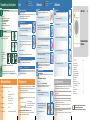
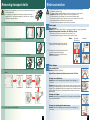
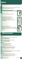
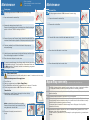
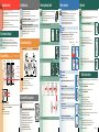
Safety instructions Installation area The washer dryer is heavy take care when lifting it. Warning: frozen hoses may tear/burst. Do not install the washer dryer outdoors or in areas where there is a risk of frost. The washer dryer may be damaged. Do not lift by projecting components (e.g. washer dryer door). In addition to the instructions mentioned here, special regulations of the relevant water and power supply companies may apply. If in doubt, have the appliance connected by a technician. Lay hoses and cables in such a way that there is no risk that they can be tripped over. Environmental disposal Dispose of packaging in an environmentally friendly manner. This appliance has been identified in accordance with the European Directive 2002/96/EEC on Waste Electrical and Electronic Equipment (WEEE). The Directive specifies aâframework for the return and recycling of waste appliances and is valid throughout Europe. Water connection Removing transport bolts Stability is important to prevent the machine from wandering. The installation area must be firm and level. Soft floors/floor coverings are not suitable. Ensure the area is well ventilated to achieve good drying performance. Risk of electric shock! Do not immerse the Aqua-Stop safety device in water (containsâanâelectric valve). To prevent leakage or water damage, follow the instructions in this chapter. Attention: operate the washer dryer with cold drinking water only. Do not connect to the mixer tap of a pressureless hot-water heater. Do not use a used inlet hose. Only use the inlet hose supplied or one which was purchased from an authorised specialist dealer. If in doubt, have the appliance connected by a technician. Before using the appliance for the first time, always remove and retain all 4 transport bolts. If transporting the appliance subsequently, always re-install the transport bolts this prevents damage to the machine. aPageâ6 Retain the screw and sleeve. If installing the appliance on a pedestal It is essential to secure the washer dryer feet with holding bracketsâ*. 1. Take the hoses out of the holder and the elbow. If installing the appliance on a wooden joist floor If possible, install the washer dryer in a corner. Screw a water-resistant wooden panel (min. 30 mm thick) to the floor. It is essential to secure the washer dryer feet with holding bracketsâ*. *âorder no. WMZ 2200, WX 9756 or High levels of noise, intense vibrations and wandering may be due to incorrect alignment. Alignment will be carried out by customer service or authorised technicians, if you want toâalign the machine by yourself please use a spirit level. Aligning the washer dryer with a spirit level. Water supply Water inlet hose: Attention: do not kink, crush, modify or cut through (strength is no longer guaranteed). Optimum water pressure in the mains: 1001000 kPa (110 bar) When the tap is turned on, the water flow is at least 8 l/min. If the water pressure is higher, install a pressure reducing valve. Hose and cable lengths Connection on left side Alignment Model: 2. Undo and remove all 4 transport bolts. Aqua-Stop Aqua-Secure Standard 3/4 1. Connect the water supply hose to the tap. Tighten plastic screw fittings by hand only. Connection on right side 1. Undo the lock nut in a clockwise direction using a wrench. 2. Adjust the height by turning the appliance foot. All four appliance feet must be placed firmly on the floor. The washer dryer must not be able to wobble. Check the alignment of the washer dryer with a spirit level andâ correct if necessary. min. 10 mm in the drum is caused Scope of delivery according to model Humiditybyâthe final inspection. ~140 cm Aqua-Stop Aqua-Secure ~90 cm 2. Carefully turn on the tap and check that the connection points are not leaking. Attention: the screw connection is under water mains pressure. 3. Take the power cord out of the holders. Remove the sleeves. Standard max. 90° max. 90° 3. Tighten the lock nut against the housing. Hold the foot in place and make sure that the height is not adjusted. The lock nuts on all four appliance feet must be screwed tightly against the housing. 3/4 ~95 cm Power cord ~160 cm ~140 cm ~165 cm min. 60 cm Water supply max. 100 cm min 10 mm Water drainage Note: if hose holders are used, the hose lengths may be reduced. Available from dealer/customer service: Aqua-Stop extension hoseâ**, approx. 2.50 m. Longer supply hose, approx. 2.20 m, for standard model. Height difference between installation area and outlet: 60100 cm Drainage into a sink/bath tub: Attention: secure the drainage hose to prevent it from slipping out ofâtheâsink. **âorder no. WMZ 2380, WZ 10130 Covers Attention: the plug must not be in the plug hole. When the water is being pumped out of the washer dryer, check that the water drains away quickly enough. Do not immerse the end of the drainage hose in the water that has been pumped out. There is a risk that water will be drawn back into the washer dryer. Hose holder Built-under/Built-in appliance Depending on the connection Aâ2440 mm dia. hose clip may also be required for connecting the siphon (available from specialist retailers). aPageâ4: Water connection Build-under/build-in before connection to the power supply. Drainage into a siphon: Attention: secure the connection with a 2440 mm dia. hose clip (available from a specialist retailer). Installed in between kitchen units (built-under or built-in) Useful tool Spirit level for aligning the washer dryer. Wrench for adjusting the machine feet. 1 Dimension requirement of kitchen unit: aâ=â650âmm, bâ=â620âmm, câ=â850âmm Install washer dryer only under a continuous worktop that is connected firmly to the adjacent cupboards. The installation area must be well ventilated, otherwise the washer dryer will operate below optimum performance. Dimension of ventilation cross-section: d x e = 200 mm x 100 mm, f = 365âmm Distance between wall and machine: 50âmm Electrical connection Water drainage hose: Attention: do not kink or stretch. 4. Insert the covers and lock them in place by pressing on the locking hook. Insert the hose holders. Water drainage e f Drainage into a plastic pipe with rubber sleeve: Attention: Secure the drainage hose to prevent it from slipping out ofâtheâdrain. 5. Fix the hoses in the hose holders. 2 3 4 ʑ ʑ ʑ ʑ Connect the washer dryer to an alternating current via a correctly installed earthed socket only. ʑ ʑ ʑ ʑ A damaged power cord may be replaced by an electrician only. A replacement power cord is available from customer service. The mains voltage and specifications on the washer dryer must match. aPageâ6: Technical specifications For information about the connected load and required fuse. aPageâ6: Technical specifications Ensure that: the mains plug and socket are compatible, the cable cross-section is adequate, the earthing system has been installed correctly. Do not use multiple plugs/connectors or extension cables. If a residual current operated circuit-breaker is used, use only a type which guarantees compliance with the currently valid regulations. Mains plug: do not insert into/pull out of the socket with damp hands. do not pull the plug out of the socket by pulling on the power cord. never pull out the plug while the appliance is in operation. Manufacturer (see Operating instructions) 0312 / 9000 479252 5 Transportation, e.g. if moving house Risk of electric shock! Pull out the mains plug! Risk of explosion! No solvents! Care 1. Before transporting the washer dryer: Maintenance Machine housing, control panel 1. Turn off the tap. 2. Release the water pressure in the supply hose. aPageâ8: Filter in the water inlet hose 3. Drain any residual detergent solution. aPageâ8: Drain pump 4. Isolate the washer dryer from the power supply. 5. Remove the hoses. Wipe with a soft, damp cloth. Do not use any abrasive cloths, scourers or cleaning agents (stainless steel cleaners). Immediately remove laundry and cleaning agent residues. Do not clean the appliance with a water jet. Risk of scalding! Allow detergent solution to cool down! Turn off the tap! Maintenance Drain pump Air inlet filter Set the programme selector to Off, disconnect the mains plug. Set the programme selector to Off, disconnect the mains plug. 1. Open and remove the service flap. Washer dryer 1. Open and remove the service flap. Clean the detergent drawer ... ... if it contains detergent or fabric softener residue. 2. Remove the air inlet filter. 2. Release the drainage hose from the clip. Remove the sealing plug from the drainage hose, allow the detergent solution to flow out. Push the sealing cap back in. 1. Pull out the drawer up to the stop position, press down the latch onâtheâinsert and remove the drawer completely. 2. Installing transport bolts: 2. Remove insert: pull insert upwards with finger. 1. Remove the covers. If necessary, remove the retainer according to the right picture. 3. Clean the fluff on the air inlet filter with water and a brush. 3. Remove the pump cap. Remove foreign objects/loose debris/fluff from inside and clean the pump. (impeller in the pump must be able to rotate). 3. Clean the detergent dispenser and the insert with water and a brush. 4. Refit the insert and secure in place (the cylinder should fit over the guideâpin). Installation maintenance instructions 4. Clean any residual lye or fluff from the thread of the pump cap andâpumphousing. 4. Place the air inlet filter back on and close. 5. Insert the detergent drawer. 2. Insert all 4 sleeves. Clamp the power cord into the holders. Insert the screws and tighten. 5. Attach the pump cap and screw it on tight until the stop, handle is upright. Place the drainage hose back in the retainer. 6. Leave the detergent drawer open so that residual water can evaporate. Drum 6. Place the service flap back on and close. Leave the washer dryer door open after washing so that the drum can dry. Rust stains use chlorine-free cleaning agent, not steel wool. Descaling No laundry in the machine! This is not necessary if the detergent is dosed correctly. However, if it is necessary, follow the instructions of the descaler manufacturer. Suitable descaling products can be purchased from our website or after-sales service. To prevent unused detergent from flowing into the outlet during the next wash: Pour 1 litre of water into dispenser II and start the Empty (Drain) or Spin programme. Contents To prevent unused detergent from flowing straight into the drain during the next wash cycle: pour 1 litre of water into compartment II and start the Spin programme. Then select and start a new washing programme with detergent as usual. The transport bolts must be removed after transportation. aPageâ3 5. Place the service flap back on and close. Filter in the water inlet hose Risk of electric shock Do not immerse the Aqua-Stop safety device in water (it contains an electric valve). Reduce the water pressure in the supply hose: Technical specifications ʑ ʑ ʑ ʑ ʑ ʑ Dimensions (width x depth x height) 600 x 600 x 850 mm Weight 84,5 kg Power supply Nominal voltage 220240âV, 50 Hz Max. current 10A Max. washing power 2400 W Max. drying power 1900 W Water pressure 1001000 kPa (110 bar) Drain height 60100 cm Test programmes According valid European Standard EN50229 en After-sales service you cannot rectify the fault yourself aOperating instructions, page 12, 13: What to do if..., ʑ Ifplease contact our after-sales service. We will always find a suitable solution and will avoid a 1. 2. 3. 4. ʑ ʑ 1. Depending on model: Remove the supply hose from the tap. Clean the filter with a small brush. visit from a service technician wherever possible. The contact details for all countries can be found in the enclosed after-sales service directory. 6 In addition to warranty claims against the seller based on the contract of sale and in addition to our appliance warranty, we shall pay damages under the following conditions: Clean the filter: 1. If water damage was caused by a fault in our Aqua-Stop system, we shall compensate private users for damage. Production number You will find this information: on the inside of the washer dryer door*/opened service flap* and rear of the appliance. *depending on the model Rely on the professionalism of the manufacturer. Please contact us. This will ensure that the repair is carried out by trained service technicians who arrive equipped with genuine spare parts for your appliance. 3. A claim can only be made under the warranty if the appliance and Aqua-Stop have been correctly installed and connected according to our instructions; this also includes a correctly installed Aqua-Stop extension (genuine accessory). Our warranty does not extend to defective supply lines or fittings up to the Aqua-Stop connection on the tap. and/or on standard and Aqua-Secure models: Remove the hose from the rear, remove the filter using pliers and clean the filter. 4. Appliances which feature Aqua-Stop can be left unattended during operation and it is not necessary to turn off the tap afterwards. The tap should only be turned off if you are away for a prolonged period, e.g. several weeks holiday. 2. Reconnect the supply hose and check if it is tight. 7 Safety instructions . . . . . . . . . . . . . . . . . . . . . . . . . . Environmental disposal . . . . . . . . . . . . . . . . . . . . . . Scope of delivery. . . . . . . . . . . . . . . . . . . . . . . . . . . Installation area . . . . . . . . . . . . . . . . . . . . . . . . . . . . Hose and cable lengths . . . . . . . . . . . . . . . . . . . . . Built-under/Built-in appliance . . . . . . . . . . . . . . . . . . Removing transport bolts . . . . . . . . . . . . . . . . . . . . Water connection . . . . . . . . . . . . . . . . . . . . . . . . . . Alignment . . . . . . . . . . . . . . . . . . . . . . . . . . . . . . . . Electrical connection . . . . . . . . . . . . . . . . . . . . . . . . Transportation, e.g. if moving house . . . . . . . . . . . . Technical specifications. . . . . . . . . . . . . . . . . . . . . . Care . . . . . . . . . . . . . . . . . . . . . . . . . . . . . . . . . . . . After-sales serevice . . . . . . . . . . . . . . . . . . . . . . . . . Maintenance . . . . . . . . . . . . . . . . . . . . . . . . . . . . . . Aqua-Stop warranty . . . . . . . . . . . . . . . . . . . . . . . . . Page ...1 ...1 ...1 ...2 ...2 ...2 ...3 ...4 ...5 ...5 ...6 ...6 ...7 ...7 . 8/9 ...9 2. The liability warranty applies to the service life of the appliance. Please give the after-sales service the product number (E-Nr.) and the production number (FD) of the appliance. Product number ʑ Aqua-Stop warranty for appliances with Aqua-Stop only Turn off the tap. Select any programme (except Spin or Empty(Drain)). Touch Start button and allow the programme to run for approx. 40 seconds. Set the programme selector to Off. Disconnect the mains plug. ʋ ʋ ʋ ʋ ʋ ʋ ʋ ʋ ʋ ʋ ʋ ʋ ʋ ʋ ʋ ʋ 8 9 Read these instructions before switching on the washer dryer. Also follow the separate Operating instructions. Retain all documents for subsequent use or for the next owner. Safety instructions Installation area The washer dryer is heavy take care when lifting it. Warning: frozen hoses may tear/burst. Do not install the washer dryer outdoors or in areas where there is a risk of frost. The washer dryer may be damaged. Do not lift by projecting components (e.g. washer dryer door). In addition to the instructions mentioned here, special regulations of the relevant water and power supply companies may apply. If in doubt, have the appliance connected by a technician. Lay hoses and cables in such a way that there is no risk that they can be tripped over. Environmental disposal Dispose of packaging in an environmentally friendly manner. This appliance has been identified in accordance with the European Directive 2002/96/EEC on Waste Electrical and Electronic Equipment (WEEE). The Directive specifies aâframework for the return and recycling of waste appliances and is valid throughout Europe. Stability is important to prevent the machine from wandering. The installation area must be firm and level. Soft floors/floor coverings are not suitable. Ensure the area is well ventilated to achieve good drying performance. If installing the appliance on a pedestal It is essential to secure the washer dryer feet with holding bracketsâ*. If installing the appliance on a wooden joist floor If possible, install the washer dryer in a corner. Screw a water-resistant wooden panel (min. 30 mm thick) to the floor. It is essential to secure the washer dryer feet with holding bracketsâ*. *âorder no. WMZ 2200, WX 9756 Hose and cable lengths Connection on left side or Connection on right side in the drum is caused Scope of delivery according to model Humiditybyâthe final inspection. ~140 cm Aqua-Secure ~90 cm Standard ~95 cm Power cord ~160 cm ~140 cm ~165 cm min. 60 cm Water supply max. 100 cm Aqua-Stop Water drainage Note: if hose holders are used, the hose lengths may be reduced. Available from dealer/customer service: Aqua-Stop extension hoseâ**, approx. 2.50 m. Longer supply hose, approx. 2.20 m, for standard model. **âorder no. WMZ 2380, WZ 10130 Covers Hose holder Built-under/Built-in appliance Depending on the connection Aâ2440 mm dia. hose clip may also be required for connecting the siphon (available from specialist retailers). aPageâ4: Water connection Build-under/build-in before connection to the power supply. Installed in between kitchen units (built-under or built-in) Useful tool Spirit level for aligning the washer dryer. Wrench for adjusting the machine feet. 1 Dimension requirement of kitchen unit: aâ=â650âmm, bâ=â620âmm, câ=â850âmm Install washer dryer only under a continuous worktop that is connected firmly to the adjacent cupboards. The installation area must be well ventilated, otherwise the washer dryer will operate below optimum performance. Dimension of ventilation cross-section: d x e = 200 mm x 100 mm, f = 365âmm Distance between wall and machine: 50âmm e f 2 Water connection Removing transport bolts Risk of electric shock! Do not immerse the Aqua-Stop safety device in water (containsâanâelectric valve). To prevent leakage or water damage, follow the instructions in this chapter. Attention: operate the washer dryer with cold drinking water only. Do not connect to the mixer tap of a pressureless hot-water heater. Do not use a used inlet hose. Only use the inlet hose supplied or one which was purchased from an authorised specialist dealer. If in doubt, have the appliance connected by a technician. Before using the appliance for the first time, always remove and retain all 4 transport bolts. If transporting the appliance subsequently, always re-install the transport bolts this prevents damage to the machine. aPageâ6 Retain the screw and sleeve. 1. Take the hoses out of the holder and the elbow. Water supply Water inlet hose: Attention: do not kink, crush, modify or cut through (strength is no longer guaranteed). Optimum water pressure in the mains: 1001000 kPa (110 bar) When the tap is turned on, the water flow is at least 8 l/min. If the water pressure is higher, install a pressure reducing valve. Model: 2. Undo and remove all 4 transport bolts. Aqua-Stop Aqua-Secure Standard 3/4 1. Connect the water supply hose to the tap. Tighten plastic screw fittings by hand only. min. 10 mm 2. Carefully turn on the tap and check that the connection points are not leaking. Attention: the screw connection is under water mains pressure. 3. Take the power cord out of the holders. Remove the sleeves. max. 90° max. 90° 3/4 min 10 mm Water drainage Water drainage hose: Attention: do not kink or stretch. 4. Insert the covers and lock them in place by pressing on the locking hook. Insert the hose holders. Height difference between installation area and outlet: 60100 cm Drainage into a sink/bath tub: Attention: secure the drainage hose to prevent it from slipping out ofâtheâsink. Attention: the plug must not be in the plug hole. When the water is being pumped out of the washer dryer, check that the water drains away quickly enough. Do not immerse the end of the drainage hose in the water that has been pumped out. There is a risk that water will be drawn back into the washer dryer. Drainage into a siphon: Attention: secure the connection with a 2440 mm dia. hose clip (available from a specialist retailer). Drainage into a plastic pipe with rubber sleeve: Attention: Secure the drainage hose to prevent it from slipping out ofâtheâdrain. 5. Fix the hoses in the hose holders. 3 4 Alignment High levels of noise, intense vibrations and wandering may be due to incorrect alignment. Alignment will be carried out by customer service or authorised technicians, if you want toâalign the machine by yourself please use a spirit level. Aligning the washer dryer with a spirit level. 1. Undo the lock nut in a clockwise direction using a wrench. 2. Adjust the height by turning the appliance foot. All four appliance feet must be placed firmly on the floor. The washer dryer must not be able to wobble. Check the alignment of the washer dryer with a spirit level andâ correct if necessary. 3. Tighten the lock nut against the housing. Hold the foot in place and make sure that the height is not adjusted. The lock nuts on all four appliance feet must be screwed tightly against the housing. Electrical connection ʑ ʑ ʑ ʑ Connect the washer dryer to an alternating current via a correctly installed earthed socket only. ʑ ʑ ʑ ʑ A damaged power cord may be replaced by an electrician only. A replacement power cord is available from customer service. The mains voltage and specifications on the washer dryer must match. aPageâ6: Technical specifications For information about the connected load and required fuse. aPageâ6: Technical specifications Ensure that: the mains plug and socket are compatible, the cable cross-section is adequate, the earthing system has been installed correctly. Do not use multiple plugs/connectors or extension cables. If a residual current operated circuit-breaker is used, use only a type which guarantees compliance with the currently valid regulations. Mains plug: do not insert into/pull out of the socket with damp hands. do not pull the plug out of the socket by pulling on the power cord. never pull out the plug while the appliance is in operation. Manufacturer (see Operating instructions) 0312 / 9000 479252 5 Transportation, e.g. if moving house Care 1. Before transporting the washer dryer: Machine housing, control panel 1. Turn off the tap. 2. Release the water pressure in the supply hose. aPageâ8: Filter in the water inlet hose 3. Drain any residual detergent solution. aPageâ8: Drain pump 4. Isolate the washer dryer from the power supply. 5. Remove the hoses. 2. Risk of electric shock! Pull out the mains plug! Risk of explosion! No solvents! Wipe with a soft, damp cloth. Do not use any abrasive cloths, scourers or cleaning agents (stainless steel cleaners). Immediately remove laundry and cleaning agent residues. Do not clean the appliance with a water jet. Clean the detergent drawer ... ... if it contains detergent or fabric softener residue. 1. Pull out the drawer up to the stop position, press down the latch onâtheâinsert and remove the drawer completely. Installing transport bolts: 2. Remove insert: pull insert upwards with finger. 1. Remove the covers. If necessary, remove the retainer according to the right picture. 3. Clean the detergent dispenser and the insert with water and a brush. 4. Refit the insert and secure in place (the cylinder should fit over the guideâpin). 5. Insert the detergent drawer. 2. Insert all 4 sleeves. Clamp the power cord into the holders. Insert the screws and tighten. 6. Leave the detergent drawer open so that residual water can evaporate. Drum Leave the washer dryer door open after washing so that the drum can dry. Rust stains use chlorine-free cleaning agent, not steel wool. The transport bolts must be removed after transportation. aPageâ3 Descaling No laundry in the machine! This is not necessary if the detergent is dosed correctly. However, if it is necessary, follow the instructions of the descaler manufacturer. Suitable descaling products can be purchased from our website or after-sales service. To prevent unused detergent from flowing into the outlet during the next wash: Pour 1 litre of water into dispenser II and start the Empty (Drain) or Spin programme. Technical specifications ʑ ʑ ʑ Dimensions (width x depth x height) 600 x 600 x 850 mm Weight 84,5 kg Power supply Nominal voltage 220240âV, 50 Hz Max. current 10A Max. washing power 2400 W Max. drying power 1900 W ʑ ʑ ʑ Water pressure 1001000 kPa (110 bar) Drain height 60100 cm Test programmes After-sales service you cannot rectify the fault yourself aOperating instructions, page 12, 13: What to do if..., ʑ Ifplease contact our after-sales service. We will always find a suitable solution and will avoid a visit from a service technician wherever possible. ʑ ʑ The contact details for all countries can be found in the enclosed after-sales service directory. Please give the after-sales service the product number (E-Nr.) and the production number (FD) of the appliance. Product number ʑ According valid European Standard EN50229 6 Production number You will find this information: on the inside of the washer dryer door*/opened service flap* and rear of the appliance. *depending on the model Rely on the professionalism of the manufacturer. Please contact us. This will ensure that the repair is carried out by trained service technicians who arrive equipped with genuine spare parts for your appliance. 7 Maintenance Risk of scalding! Allow detergent solution to cool down! Turn off the tap! Maintenance Drain pump Air inlet filter Set the programme selector to Off, disconnect the mains plug. Set the programme selector to Off, disconnect the mains plug. 1. Open and remove the service flap. 1. Open and remove the service flap. 2. Remove the air inlet filter. 2. Release the drainage hose from the clip. Remove the sealing plug from the drainage hose, allow the detergent solution to flow out. Push the sealing cap back in. 3. Clean the fluff on the air inlet filter with water and a brush. 3. Remove the pump cap. Remove foreign objects/loose debris/fluff from inside and clean the pump. (impeller in the pump must be able to rotate). 4. Clean any residual lye or fluff from the thread of the pump cap andâpumphousing. 4. Place the air inlet filter back on and close. 5. Attach the pump cap and screw it on tight until the stop, handle is upright. Place the drainage hose back in the retainer. 6. Place the service flap back on and close. To prevent unused detergent from flowing straight into the drain during the next wash cycle: pour 1 litre of water into compartment II and start the Spin programme. Then select and start a new washing programme with detergent as usual. 5. Place the service flap back on and close. Filter in the water inlet hose Risk of electric shock Do not immerse the Aqua-Stop safety device in water (it contains an electric valve). Reduce the water pressure in the supply hose: 1. 2. 3. 4. Aqua-Stop warranty for appliances with Aqua-Stop only Turn off the tap. Select any programme (except Spin or Empty(Drain)). Touch Start button and allow the programme to run for approx. 40 seconds. Set the programme selector to Off. Disconnect the mains plug. In addition to warranty claims against the seller based on the contract of sale and in addition to our appliance warranty, we shall pay damages under the following conditions: Clean the filter: 1. If water damage was caused by a fault in our Aqua-Stop system, we shall compensate private users for damage. 1. Depending on model: Remove the supply hose from the tap. Clean the filter with a small brush. 2. The liability warranty applies to the service life of the appliance. 3. A claim can only be made under the warranty if the appliance and Aqua-Stop have been correctly installed and connected according to our instructions; this also includes a correctly installed Aqua-Stop extension (genuine accessory). Our warranty does not extend to defective supply lines or fittings up to the Aqua-Stop connection on the tap. and/or on standard and Aqua-Secure models: Remove the hose from the rear, remove the filter using pliers and clean the filter. 4. Appliances which feature Aqua-Stop can be left unattended during operation and it is not necessary to turn off the tap afterwards. The tap should only be turned off if you are away for a prolonged period, e.g. several weeks holiday. 2. Reconnect the supply hose and check if it is tight. 8 9 Washer dryer en Installation maintenance instructions Contents ʋ ʋ ʋ ʋ ʋ ʋ ʋ ʋ ʋ ʋ ʋ ʋ ʋ ʋ ʋ ʋ Safety instructions . . . . . . . . . . . . . . . . . . . . . . . . . . Environmental disposal . . . . . . . . . . . . . . . . . . . . . . Scope of delivery. . . . . . . . . . . . . . . . . . . . . . . . . . . Installation area . . . . . . . . . . . . . . . . . . . . . . . . . . . . Hose and cable lengths . . . . . . . . . . . . . . . . . . . . . Built-under/Built-in appliance . . . . . . . . . . . . . . . . . . Removing transport bolts . . . . . . . . . . . . . . . . . . . . Water connection . . . . . . . . . . . . . . . . . . . . . . . . . . Alignment . . . . . . . . . . . . . . . . . . . . . . . . . . . . . . . . Electrical connection . . . . . . . . . . . . . . . . . . . . . . . . Transportation, e.g. if moving house . . . . . . . . . . . . Technical specifications. . . . . . . . . . . . . . . . . . . . . . Care . . . . . . . . . . . . . . . . . . . . . . . . . . . . . . . . . . . . After-sales serevice . . . . . . . . . . . . . . . . . . . . . . . . . Maintenance . . . . . . . . . . . . . . . . . . . . . . . . . . . . . . Aqua-Stop warranty . . . . . . . . . . . . . . . . . . . . . . . . . Page ...1 ...1 ...1 ...2 ...2 ...2 ...3 ...4 ...5 ...5 ...6 ...6 ...7 ...7 . 8/9 ...9 Read these instructions before switching on the washer dryer. Also follow the separate Operating instructions. Retain all documents for subsequent use or for the next owner.