1
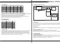
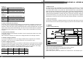
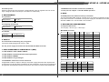
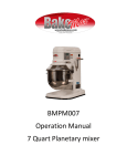
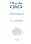
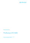
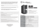
STRIDER GOLD SERIES
ST65F-G / ST55F-G
The perfect balance of performance, effiency, and quality
lssue date: June, 2012
NO. G11216330
Compact design with a depth of 140mm for easy integration
80Plus Gold certification with higher efficiency 87%~90% at 20%~100% loading
100% modular cables
24/7 continuous power output with 40 C operating temperature
Class-leading single +12V rail
Strict ±3% voltage regulation and low ripple & noise
Silent running 120mm fan with 18dBA minimum
O
ST65F-G / ST55F-G
SilverStone Strider Gold
ST65F-G
ST55F-G
ATX12V / EPS 12V Switching Power Supply
With Active PFC
80Plus Gold
PS/2
1.2 Inrush current regulation
The power supply must meet inrush requirements for any rated AC voltage, during
turn on at any phase of AC voltage, during a single cycle AC dropout condition,
during repetitive ON/OFF cycling of AC, and over the specified temperature range
(Top). The peak inrush current shall be less than the ratings of its critical components
(including input fuse, bulk rectifiers, and surge limiting device).
2. DC OUTPUT
2.1 DC voltage regulation
Parameter
Range
+3.3V
+5V
Min
Nom.
Max
Unit
+/-3%
+3.2
+3.3
+3.39
Volts
+/-3%
+4.85
+5
+5.15
Volts
+12V
+/-3%
+11.64
+12.0
+12.36
Volts
-12V
+/-10%
-10.8
-12.0
-13.2
Volts
+/-5%
+4.75
+5
+5.25
Volts
+5VSB
This specification describes the requirements of 550W, 650Watts switching. power
supply with an stretch ATX form-factor and EPS 12V, +5V standby voltage, remote
on/off control, full range line input capability and forced air cooling characteristics.
Note:
1.Voltage tolerance is requied at main connector and S-ATA connector(if used).
2.Output transient response tested DC voltage regulation range +5V±5%, +12V±5%,
+3.3V±5%, +5Vsb±5%, -12V±10%.
1. AC INPUT
1.1 AC input requirements
The input voltage, current, and frequency requirements for continuous operation
are stated below.
Table 1 AC Input Line Requirements
2.2 Load ranges
2.2.1: (ST55F-G)
Parameter
Min
Nom.
Max
Peak
Unit
+3.3V
0.2
-
22
Amps
+5V
0.2
-
18
Amps
Parameter
Min.
Nom.
Max.
Unit
+12V
0.3
-
45
48
Amps
Vin( Full range )
90
100---240
264
VACrms
-12V
0
-
0.3
Amps
Vin Frequency
47
60-----50
63
Hz
+5VSB
0
-
2.5
3.5
Amps
Iin(ST55F-G)
7------3.5
Arms
Iin(ST65F-G)
8--------4
Arms
Power factor correction (PF)>0.90 at full load.
1.Maximum continuous total DC output power should not exceed 550W.
2.Maximum continuous combined load on +3.3V and +5V outputs shall not exceed 140W.
3.Maximum combined current for the +12V outputs shall be 45A(540W).
4.Maximum peak total DC output power should not exceed 600W.
5.Peak power and current loading shall be supported for a minimum of 12 second.
6.When +12V is load to 25A , -12V minimum load is 0.02A.
ST65F-G / ST55F-G
2.2.2: (ST65F-G)
2.3.3 Ripple voltage test circuit
Parameter
Min
Nom.
Max
Peak
Unit
+3.3V
0.2
-
22
Amps
+5V
0.2
-
20
Amps
+12V
0.3
-
54
57
Amps
-12V
0
-
0.3
Amps
+5VSB
0
-
2.5
3.5
Amps
Power Supply
AC H o t
V out
10uF
V re tu rn
AC N e u tra l
0 .1 u F
Load
AC G ro u n d
1.Maximum continuous total DC output power should not exceed 650W.
2.Maximum continuous combined load on +3.3V and +5V outputs shall not exceed 150W.
3.Maximum combined current for the +12V outputs shall be 54A(648W).
4.Maximum peak total DC output power should not exceed 700W.
5.Peak power and current loading shall be supported for a minimum of 12 second.
6.When +12V is load to 25A , -12V minimum load is 0.02A.
S cope
2.3 Output Ripple
2.3.1 Ripple regulation
Figure 1. Ripple voltage test circuit
Parameter
Ripple&Noise
Unit
+3.3V
50
mVp-p
+5V
50
mVp-p
+12V1
120
mVp-p
+12V2
120
mVp-p
-12V
100
mVp-p
50
mVp-p
+5VSB
2.3.2 Definition
The ripple voltage of the outputs shall be measured at the pins of the output connector
when terminated in the load impedance specified in figure 1. Ripple and noise are
measured at the connectors with a 0.1uF ceramic capacitor and a 10uF electrolytic
capacitor to simulate system loading. Ripple shall be measured under any condition of
line voltage, output load, line frequency, operation temperature.
2.4 Overshoot
Any overshoot at turn on or turn off shall be less 10% of the norminal voltage value, all
outputs shall be within the regulation limit of section 2.0 before issuing the power good
signal of section 5.0.
2.5 Efficiency
Power supply efficiency typical 87% for at normal voltage at full load on all outputs.
2.6 Remote ON/OFF control
When the logic level "PS-ON" is low, the DC outputs are to be enabled.
When the logic level is high or open collector, the DC outputs are to be disabled.
3.0 PROTECTION
3.1 Over current protection
The power supply shall have current limit to prevent the +3.3V, +5V, and +12V1, +12V2
outputs from exceeding the values shown in the following Table.If the current limits are
exceeded the power supply shall shutdown and latch off.
ST65F-G / ST55F-G
ST55F-G
Voltage
Over Current Limit (Iout limit)
+12V
50A minimum; 65A maximum
+5V
25A minimum; 40A maximum
+3.3V
27A minimum; 45A maximum
3.6 Short circuit
An output short circuit is defined as any output impedance of less than 0.1 ohms.
The power supply shall shut down and latch off for shorting the +3.3 VDC, +5 VDC,
or+12 VDC rails to return or any other rail. Shorts between main output rails and +5VSB
shall not cause any damage to the power supply. The power supply shall either shut
down and latch off or fold back for shorting the negative rails.+5VSB must be capable
of being shorted indefinitely, but when the short is removed, the power supply shall
recover automatically or by cycling PS_ON#. The power supply shall be capable of
withstanding a continuous short-circuit to the output without damage or overstress to the unit.
ST65F-G
Voltage
Over Current Limit (Iout limit)
+12V
58A minimum; 70A maximum
+5V
25A minimum; 40A maximum
+3.3V
27A minimum; 45A maximum
3.7 No load operation
No damage or hazardous condition should occur with all the DC output connectors
disconnected from the load.The power supply may latch into the shutdown state.
3.2 Over Temperature Protection
The power supply will be protected against over temperature conditions caused by loss
of fan cooling or excessive ambient temperature. In an OTP condition the PSU will
shutdown. When the power supply temperature drops to within specifide limits, the power
supply shall restore power automatically. The OTP circuit must have built in hysteresis
such that the power supply will not oscillate on and off due to temperature recovering
condition.
4. TIMING
4.1 Signal timing drawing
3.3 Over-power protection
The power supply will be shutdown and latch off when output power within 105~150%
of rated DC output.
Note: Assurance machine can work at low voltage,full load won't damage machine.
3.4 Under voltage protection
In an under voltage fault occurs, the supply will latch all DC outputs into a shutdown
state when +12V,+5V & +3.3V outputs under 85% of it's maximum value.
3.5 Over voltage protection
The over voltage sense circuitry and reference shall reside in packages that are separate
and distinct from the regulator control circuity and reference. No single point fault shall
be able to cause a sustained over voltage condition on any or all outputs. The supply
shall provide latch-mode over voltage protection as defined in Table.
output
+12 VDC
+5 VDC
+3.3 VDC
Minimum
Nominal
Maximum
Unit
13.3
15.6
16.5
Volts
6.30
7.00
Volts
4.3
4.50
Volts
Figure 2. PS-OK Timing Sequence
(1)T3: Power good signal turn on delay time (100ms~500ms)
(2)T4: Power good signal turn off delay time (1ms min)
(3)T2: Rise time (0.1~20ms)
(4)T6: Hold up time (16ms min) Tested at full load and over 100-240VAC input.
ST65F-G / ST55F-G
4.2 Hold up time
When the power loss its input power, it shall maintain 16ms in regulation limit at normal
input voltage and 80% full load (AC:115V/60Hz or 230V/50Hz)
7.6 EN55024 class B radio interference (CISPR 22)
7.7 FCC part 15, subpart J class B 115VAC operation.
8. MTBF
5. ENVIRONMENT
5.1 Operation
O
Temperature
0 to 40 C
Relative Humidity
10 to 90%, non-condensing
8.1 MTBF(mean time between failures) calculation
The demonstrated MTBF shall be 100,000 hours of continuous operation at 25oC, full
load, and nominal line. The MTBF of the power supply be calculated in accordance
with MIL-HDBK-217F. The DC FAN is not included.
9. MECHANICAL REQUIREMENTS
5.2 Shipping and Storage
O
Temperature
-20 to 60 C
Relative Humidity
5 to 95%, non-condensing
9.1 Physical Dimension
150 mm (W) × 86 mm (H) × 140mm (D)
M/B 24PIN connector
5.3 Altitude
Operating
10,000FT max
Storage
50,000FT max
6. SAFETY
6.1 Underwriters Laboratory (UL) recognition.
The power supply designed to meet UL 1950.
6.2 The power supply must bear the German Bauart Mark from TUV.
Signal
Pin
Pin
Signal
Orange
+3.3V
13
1
+3.3V
Orange
Blue
-12VDC
14
2
+3.3V
Orange
Black
COM
15
3
COM
Black
Green
PS-ON
16
4
+5VDC
Red
Black
COM
17
5
COM
Black
Black
COM
18
6
+5VDC
Red
Black
COM
19
7
COM
Black
White
N/C
20
8
PWRGOOD
Grey
Red
+5VDC
21
9
+5Vsb
Purple
7.1 IEC 61000-4-2 ESD LEVEL X20KV4.
Red
+5VDC
22
10
+12V
Yellow
7.2 IEC 61000-4-3 radiated electrical field requirement.
Red
+5VDC
23
11
+12V
Yellow
7.3 IEC 61000-4-4 BURST .
Black
COM
24
12
+3.3V
Orange
7. ELECTROMAGNETIC COMPATIBILITY (EMC)
7.4 IEC 61000-4-5 surge Voltages
7.5 EN61000-3-2 harmonic current emissions.
If applicable to sales in Japan or Europe, the power supply shall meet the requirements
of EN 61000-3-2 class D and the guidelines for the suppression of harmonics in appliances
and general use equipment class D for harmonic line current content at full-rated power.
EPS 12V 8PIN connector
Signal
Pin
Pin
Signal
Yellow
+12V
5
1
COM
Black
Yellow
+12V
6
2
COM
Black
Yellow
+12V
7
3
COM
Black
Yellow
+12V
8
4
COM
Black
ST65F-G / ST55F-G
Warranty Information
ATX 12V 4PIN (4+4PIN EPS 12V in split mode)
Signal
Pin
Pin
Signal
Black
GND
1
3
+12V
Yellow
Black
GND
2
4
+12V
Yellow
4PIN peripheral connector (HDD)
This product has a limited 3 year warranty in North America, Europe, and Australia.
For information on warranty periods in other regions, please contact your reseller or SilverStone authorized distributor.
Warranty terms & conditions
4PIN floppy connector (FDD)
Signal
Pin
Pin
Signal
Yellow
+12V
1
1
+5VDC
Red
Black
COM
2
2
COM
Black
Black
COM
3
3
COM
Black
+5VDC
4
4
+12V
Yellow
Red
1. Product component defects or damages resulted from defective production is covered under warranty.
Defects or damages with the following conditions will be fixed or replaced under SilverStone Technology’s jurisdiction.
a) Usage in accordance with instructions provided in this manual, with no misuse, overuse, or other inappropriate actions.
b) Damage not caused by natural disaster (thunder, fire, earthquake, flood, salt, wind, insect, animals, etc…)
c) Product is not disassembled, modified, or fixed. Components not disassembled or replaced.
d) Warranty mark/stickers are not removed or broken.
Loss or damages resulted from conditions other than ones listed above are not covered under warranty.
2. Under warranty, SilverStone Technology’s maximum liability is limited to the current market value for the product (depreciated value, excluding
shipping, handling, and other fees). SilverStone Technology is not responsible for other damages or loss associated with the use of product.
3. Under warranty, SilverStone Technology is obligated to repair or replace its defective products. Under no circumstances will SilverStone
Technology be liable for damages in connection with the sale, purchase, or use including but not limited to loss of data, loss of business, loss of
profits, loss of use of the product or incidental or consequential damage whether or not foreseeable and whether or not based on breach of warranty,
contract or negligence, even if SilverStone Technology has been advised of the possibility of such damages.
4. Warranty covers only the original purchaser through authorized SilverStone distributors and resellers and is not transferable to a second hand
purchaser.
SATA connector
5. You must provide sales receipt or invoice with clear indication of purchase date to determine warranty eligibility.
Signal
Pin
Orange
+3.3V
5
Black
COM
4
Red
+5V
3
Black
COM
2
Yellow
+12V
1
6. If a problem develops during the warranty period, please contact your retailer/reseller/SilverStone authorized distributors or SilverStone
http://www.silverstonetek.com.
Please note that: (i) You must provide proof of original purchase of the product by a dated itemized receipt; (ii) You shall bear the cost of shipping
(or otherwise transporting) the product to SilverStone authorized distributors. SilverStone authorized distributors will bear the cost of shipping
(or otherwise transporting) the product back to you after completing the warranty service; (iii) Before you send the product, you must be issued a
Return Merchandise Authorization (“RMA”) number from SilverStone. Updated warranty information will be posted on SilverStone’s official website.
Please visit http://www.silverstonetek.com for the latest updates.
Additional info & contacts
8PIN PCI Express connector
Signal
Pin
Pin
Signal
Yellow
+12V
1
5
COM
Black
Yellow
+12V
2
6
COM
Black
Yellow
+12V
3
7
COM
Black
Black sense1
COM
4
8
COM
Black
For North America ([email protected])
SilverStone Technology in North America may repair or replace defective product with refurbished product that is not new but has been functionally tested.
Replacement product will be warranted for remainder of the warranty period or thirty days, whichever is longer. All power supplies should be sent
back to the place of purchase if it is within 30 days of purchase, after 30 days, customers need to initiate RMA procedure with SilverStone Technology
in USA by first downloading the “USA RMA form for end-users” form from the below link and follow its instructions.
http://silverstonetek.com/contactus.php
For Australia only ([email protected])
Our goods come with guarantees that cannot be excluded under the Australian Consumer Law.
You are entitled to a replacement or refund for a major failure and for compensation for any other reasonably foreseeable loss or damage.
You are also entitled to have the goods repaired or replaced if the goods fail to be of acceptable quality and the failure does not amount to a major failure.
Please refer to above “Warranty terms & conditions” for further warranty details.
SilverStone Technology Co., Ltd. 12F No. 168 Jiankang Rd., Zhonghe Dist., New Taipei City 235 Taiwan R.O.C. + 886-2-8228-1238
(standard international call charges apply)
6PIN PCI Express connector
For Europe ([email protected])
For all other regions ([email protected])
Signal
Pin
Pin
Signal
Yellow
+12V
1
4
COM
Black
Yellow
+12V
2
5
COM
Black
Yellow
+12V
3
6
COM
Black