1
Manual
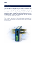
Web-IO Analog-In/Out PoE
W&T
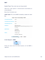
Typ
Modell
Release
10/100BaseT
57661, 57662 FW 1.76
1.76, June 2011
W&T
© 06/2012 by Wiesemann & Theis GmbH
Microsoft, MS-DOS, Windows, Winsock und Visual Basic
are registered trademarks of Microsoft Corporation
Subject to errors and modifications:
Since errors are always possible, none of this information
should be used without checking. Please let us know of any
mistakes or unclear descriptions so that we can become aware
of them and correct them as quickly as possible.
Perform work on and with W&T products only as described here
and after you have read and fully understood the manual.
Improper use may result in hazardous conditions. We are not
liable for improper use. If in doubt, please check first with us or
with your dealer!
W&T
Introduction
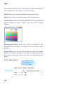
The W&T Web-IO Analog-In/Out models include all the
functions in a single box for capturing your analog
measurements (0..20mA/4..20mA or 0..10V), tunneling them
through the network, saving and displaying them. A variety of
alarm and report functions are also available which can be
custom added to your own applications or into existing
systems (Modbus-TCP, OPC, SNMP).
This manual contains all the information you need for
installation, configuration and operation of the Web-IO AnalogIn/Out devices.
W&T
Content
Introduction ............................................................................................ 3
1 Quick-start, Commissioning ......................................................... 7
1.1 Connect to power ........................................................... 7
1.2 Wiring the in- and outputs ............................................... 9
1.3 Network connection ...................................................... 11
1.4 Assigning the IP address using „WuTility“ ....................... 12
1.5 Assigning the IP address using DHCP protocol ................ 14
1.5.1 Enabling/Disabling DHCP ............................................. 15
1.5.2 System Name ............................................................... 16
1.5.3 Lease Time .................................................................. 16
1.5.4 Reserved IP addresses .................................................. 17
1.5.5 Dynamic IP addresses .................................................. 17
1.6 Start page ..................................................................... 18
1.7 Assigning the basic network parameters ......................... 19
1.8 Smartphone Page .......................................................... 23
2 Graphical Representation of the Measurements .................. 24
2.1 Basic functions ............................................................. 24
2.2 Config Menue ............................................................... 26
2.3 Table ............................................................................ 28
3 Other Basic Settings ....................................................................... 29
3.1 Configuring the port and device name ............................ 29
3.1.1 Text .................................................................. 29
3.1.2 Ports ................................................................. 30
3.1.3 Port Config ....................................................... 32
3.2 Calibration ................................................................... 33
3.3 Specifying Output Mode ................................................ 34
3.4 Compensation of the output controller (57662 only) ....... 36
3.5 HTTP - Controlling outputs in the browser (Control) ....... 38
3.6 Basic Settings HTTP ....................................................... 39
3.7 Basic Settings UDP ........................................................ 41
3.8 BINARY - Socket programs with binary structures ............ 42
3.8.1 Specifying the operating mode .......................... 43
3.8.2 The Web-IO Analog-In/Out as Socket-Server ...... 44
3.8.3 The Web-IO as Socket-Client .............................. 47
3.8.4 The Web-IO as UDP-Peer .................................... 50
4
W&T
3.8.5 Password protection ......................................... 52
3.8.6 BINARY - The IO structures ................................ 54
3.8.7 Definition of the IO structures ........................... 55
3.8.8 Working with the IO structures .......................... 56
3.9 Box-to-Box (tunneling measurement network) ................ 60
3.9.1 Configuring the Slave Web-IO (Server) ............... 61
3.9.2 Configuring the Master (Client) ......................... 63
3.9.3 Determining Box-to-Box connection status ....... 67
3.9.4 Quitting Box-to-Box mode ................................ 68
3.9.5 Quitting Box-to-Box mode
only for the Slave Web-IO ........................................... 69
3.9.6 Preconfiguring Box-to-Box for another network . 70
3.10 Modbus TCP ............................................................... 71
3.10.1 Configuration for Modbus TCP access ............. 71
3.10.2 Modbus variables for Web-IO Analog In/Out .... 74
3.10.3 Modbus-TCP device behavior .......................... 75
3.10.4 Modbus - Alarm triggering incl. special memory 76
3.10.5 Displaying Modbus variables on the user page 77
3.10.6 Modbus memory distribution .......................... 78
3.11 OPC - Standardized access .......................................... 80
3.11.1 Installing the OPC-Server ................................. 80
3.11.2 Uninstalling .................................................... 81
3.11.3 Configuring .................................................... 81
3.11.4 Configuring the Web-IO as an OPC device ....... 84
3.11.5 Program options ............................................. 86
3.11.6 Data model for OPC Data Access ..................... 88
3.11.7 OPC variables for Web-IO Analog ..................... 89
3.11.8 OPC Alarms & Events ...................................... 90
3.12 Local time setting ........................................................ 92
3.13 Automatic time setting using a network time service ...... 95
3.14 Configuring the data logger ......................................... 97
3.15 Configuring the graphics output .................................. 98
3.16 Alarms ..................................................................... 103
3.16.1 CRON service ........................................................... 105
3.17 Sending alarms via e-mail .......................................... 107
3.17.1 Basic Settings -> Mail ..................................... 107
3.17.2 Alarm X -> Mail .............................................. 109
3.18 SNMP incl. alarm sending per Trap .............................. 112
3.18.1 Basic Settings -> SNMP .................................. 112
3.18.2 Alarm X -> SNMP ........................................... 113
3.19 Sending alarms per TCP (Client Mode) ........................ 116
3.19.1 Alarm X -> TCP .............................................. 116
3.19.2 Alarm to localhost ......................................... 117
3.20 Sending alarms per FTP (Client Mode) ......................... 118
3.20.1 Basic Settings -> FTP ..................................... 118
3.20.2 Alarm X -> FTP .............................................. 120
Subject to errors and modifications
5
W&T
3.20.3 Special case: Report -> FTP ............................ 121
3.21 Syslog messages incl. alarm sending .......................... 122
3.21.1 Basic Settings -> Syslog ................................ 122
3.21.2 Alarm X -> Syslog .......................................... 123
3.22 Time-based report ..................................................... 125
3.23 Check Alarm ............................................................. 126
3.24 UP-/Download ........................................................... 127
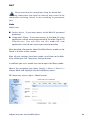
4 Individual Measurement Polling ............................................ 129
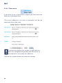
4.1.1 HTTP - Polling logger using a ASCII
command string .......................................................... 129
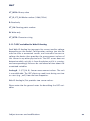
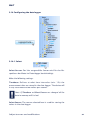
4.1.2 HTTP - Controlling outputs
of device ..................................................................... 130
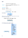
4.1.3 HTTP - Polling inputs using a ASCII
command string .......................................................... 130
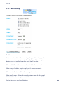
4.1.4 HTTP - Reading diagnostics infos
from device ................................................................. 132
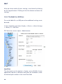
4.2 Polling via UDP ............................................................ 132
4.3 Polling via SNMP .......................................................... 133
5 Including Measurements in your own Web Page ............. 136
6 Data Logger .................................................................................... 141
7 Appendix ......................................................................................... 142
7.1 Alternative IP address assigning ................................... 142
7.2 Example for creating your own Web pages .................... 144
7.3 Firmware update ......................................................... 151
7.3.1 Where is the current firmware available? ........... 152
7.3.2 Firmware update over the network
under Windows ........................................................ 152
7.3.3 LED indicators ................................................. 153
7.4 Emergency access ....................................................... 154
7.5 Technical data ............................................................ 155
7.6 Disposal ..................................................................... 156
6
W&T
1 Quick-start, Commissioning
To start up the W&T Web-IO Analog-In/Out and make it visible
in your network only a few steps are necessary.
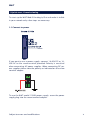
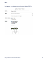
1.1 Connect to power
If you want to use a power supply, connect 18-48V DC or 1830V AC to the screw terminal provided. Polarity is uncritical
when connecting AC power supplies. When connecting DC power supplies please note the polarity as indicated on the screw
terminal adapter:
To use the W&T model 11020 power supply, screw the power
supply plug into the screw terminal adapter:
Subject to errors and modifications
7
W&T
PoE supply
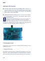
The Web-IO Analog-In/Out can be used in PoE (Power-overEthernet) environments in accordance with IEEE802.3af. The
supply voltage is provided then by the network infrastructure
through the RJ45 terminal. The device supports both phantom
power using data pairs 1/2 and 3/6 as well as power on the
unused wire pairs 4/5 and 7/8.
To enable power management for the supplying components,
the W&T Web-IO Analog-In/Out is identified as a Power Class 1
device with a power consumption of 0.44 to 3.8W.
As an alternative to PoE the device can also be powered
externally using the screw terminal located on the underside of
the device.
!
Use of the W&T Web-IO Analog-In/Out is also possible in
networks wihtout PoE. In this case simply use an external
power supply with the screw terminals as described
above. No additional configurations or settings are necessary.
8
W&T
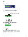
1.2 Wiring the in- and outputs
Depending on the configuration the W&T Web-IO Analog-In/Out
can be wired as follows, whereby Ports 1 and 2 are indicated by
an „X“. The configuration is identical for both ports:
1.2.1 Current input 0..20mA, passive (#57661)
1.2.2 Current input 0..20mA, active (#57661)
Note: If you need to connect two passive sensors, 1.1 and 2.1
may be jumpered in order to save wires. 1.2 and 2.2 may not be
jumpered however, since otherwise cross-currents will flow
which falsify the input values.
Subject to errors and modifications
9
W&T
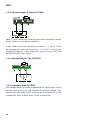
1.2.3 Current output 0..20mA (#57661)
Note: Current outputs cannot be connected directly to active
inputs. Please use isolation amplifiers.
If you need to connect two passive sensors, 1.1 and 2.1 may
be jumpered in order to save wires. 1.2 and 2.2 may not be
jumpered however, since otherwise cross-currents will flow
which falsify the input values.
1.2.4 Voltage input 0..10V (#57662)
1.2.5 Voltage output (#57662)
The voltage output must be jumpered to the Sense input, which
can be used to measure and regulate the output voltage. This
jumper can be made either directly on the device or at the
remote end. Imax in both cases 15mA at sense line.
10
W&T
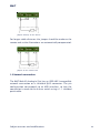
Jumper directly on the device
For longer cable distances the jumper should be made on the
remote end so that fluctuations are automatically compensated:
Jumper on the remote end
1.3 Network connection
The W&T Web-IO Analog-In/Out has an IEEE 802.3 compatible
network connection on a shielded RJ45 connector. The pin
configuration corresponds to an MDI interface, so that the
connection is made to the hub or swtich using a 1:1 shielded
patch cable.
Subject to errors and modifications
11
W&T
Power-over-Ethernet
The W&T Web-IO Analog-In/Out can obtain its supply voltage
through the network interface in accordance with IEEE802.3af /
Power-over-Internet. The feed comes in over the data pairs or
on the wire pairs not used for 10/100BaseT (see PoE section).
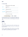
1.4 Assigning the IP address using „WuTility“
Once the hardware has been connected to the power supply as
described above, the IP address needed for operating in a TCP/
IP network must be assigned. You should obtrain the correct
value for this parameter from your systems administrator.
!
The IP address must be unique in the network.
There are various ways of assigning the IP address. To make
the procedure as convenient as possible, we have developed
the „WuTility“ tool, which you can download from the WuT
homepage at http://www.wut.de. This procedure is described
in the following. A summary of the options for assigning the IP
address can be found in the Appendix of this manual.
12
W&T
Be sure that the PC you are using to assign the IP address is
located in the same subnet as the W&T unit and that both the
PC and the unit are connected to the network.
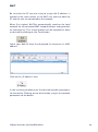
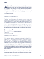
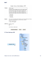
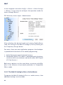
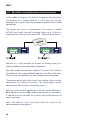
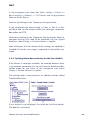
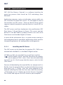
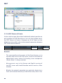
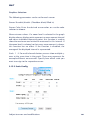
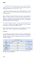
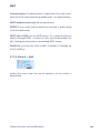
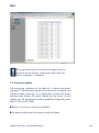
When first started, WuTility automatically searches the local
network for all connected W&T network devices and generates
an inventory list. This search process can be repeated as often
as desired by clicking on the Scan button:
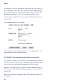
Select your Web-IO from the displayed list based on its MAC
address:
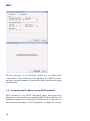
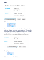
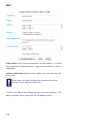
Click on the „IP address“ icon:
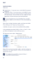
In the resulting window enter the desired network parameters
for the device. Clicking on the Next button assigns the network
parameters to the device.
Subject to errors and modifications
13
W&T
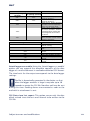
All the columns in the WuTility device list are filled with
information. After clicking on the globe in the WuTIlity menu
bar your standard browser is opened and you see the start page
of the device.
1.5 Assigning the IP address using DHCP protocol
Many networks use DHCP (Dynamic Host Configuration
Protocol) or the predecessor protocol BOOTP (described in the
following section) for centralized and dynamic assignment of
the network parameters. DHCP protocol is enabled by factory
14
W&T
default setting, so that in network environments wtih dynamic
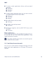
IP assignment you need only to connect the W&T Web-IO Analog-In/Out to the network. The following parameters can be set
using DHCP:
• IP address
• Subnet mask
• Gateway address
• DNS server
• Lease time
1
To prevent unintended address assignments or address
changes, we recommend disabling DHCP, BOOTP and
RARP protocols unless they are expressly used in the respective
network environment. W&T Web-IO Analog-In/Out units with
incorrectly assigned IP addresses can be conveniently located
and reconfigured using the scan function of WuTility
management tool.
1.5.1 Enabling/Disabling DHCP
The factory default setting is for DHCP protocol enabled. To
disable or enable it again later any of the following methods
may be used.
•
WuTility management tool
From the device list select the desired W&T Web-IO AnalogIn/Out and click on the IP Address button. In the dialog box
enter the new network parameters you want to assign.
Disable the options BOOTP and DHCP. Click on Next to
send the new configuration data to the W&T Web-IO Analog-In/Out.
•
Web Based Management
In the menu path Config >> Device >> Basic Settings >>
Network Network the protocols can be alternatingly enabled
or disabled. For detailed information see the section
Assigning basic network parameters.
Subject to errors and modifications
15
W&T
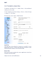
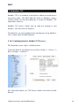
1.5.2 System Name
To suypport any automatic updating of the DNS system by the
DHCP server the W&T Web-IO Analog-In/Out identifies itself
within the DHCP protocol by its system name. The factory
default setting is WEBIO- followed by the last three places of
the Ethernet address. For example, the factory set system name
of a W&T Web-IO Analog-In/Out with Ethernet address
00:c0:3d:01.02.03 is WEBIO-010203. The system name of the
W&T Web-IO Analog-In/Out can be changed using Web Based
Management.
1.5.3 Lease Time
The lease time determined and sent by the DHCP server
specifies the term of the assigned IP address. After half the lease time has expired the W&T Web-IO Analog-In/Out attempts to
extend or update the address. If this is not possible before the
lease time expires, for example because the DHCP server can
no longer be reached, the W&T Web-IO Analog-In/Out deletes
the IP address and begins a cyclical search for alternate DHCP
servers for assigning a new IP address.
The lease time associated with the current IP address is no
longer available after a reset. After restarting, therefore, a
corresponding update request is made by the original DHCP
server. If the server cannot be reached at this time the W&T WebIO Analog-In/Out deletes the IP address and begins a cyclical
search for alternate DHCP servers.
If DHCP is enabled, the remaining lease time together with the
current IP address is displaced in seconds in the menu path
Home >> Doc >> Property.
16
W&T
1
If the DHCP server is no longer accessible after expiration
of the lease time, the W&T Web-IO Analog-In/Out deletes
its IP address. All existing TCP/UDP connections between the
W&T Web-IO Analog-In/Out and other network clients are
thereby closed. To prevent such situations, we recommend
configuring the assigned lease time in the DHCP server to infinite whenever possible.
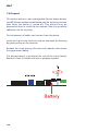
1.5.4 Reserved IP addresses
The W&T Web-IO Analog-In/Out provides services which can
make use of the other clients in the network as needed. Of
course the current IP address of the W&T Web-IO Analog-In/Out
is needed by these clients in order to open a connection, so
that in these cases it makes sense to reserve a particular IP
address for the W&T Web-IO Analog-In/Out. This is generally
done by linking the IP address to the unique Ethernet address
of the unit, which can be found on the sticker on the housing.
58xxx
[Typ]
EN=00c03d004a05
Ethernet-Adresse
OK xxxxxx
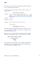
1.5.5 Dynamic IP addresses
Fully dynamic address assignment, whereby the Web-IO Analog-In/Out is given a different IP address after each restartor
after the lease time expires, is only practical in network
environments with automatic cross-linking between the DHCP
and DNS services. This means when assigning a new IP address
to the Web-IO Analog-In/Out, the DHCP server automatically
updates the DNS system as well. The new address is assigned
to the respective domain name. For detailed information about
your network environment, consult your systems administrator
when in doubt.
For time server requests, sending e-mails or other client
applications where the device itself actively seraches for server
Subject to errors and modifications
17
W&T
services located in the network, dynamic changing IP addresses
can also be used.
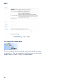
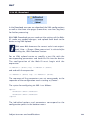
1.6 Start page
As soon as an IP address is assigned, the start page of the
device can be opened in the Web browser:
When first opened you must select the device language. Once
this is done, you are taken to the actual start page of the device.
To get to the configuration menu, click above on the page on
the „Show menu“ link. If you assign a password later in the
configuration, you can login here.
18
W&T
Also on this page you can switch to the User page to directly
read out the data logger of the unit.
Display the menu to go to the Smartphone page or to proceed
with the rest of the configuration.
1.7 Assigning the basic network parameters
At left in the configuration tree click on „Config“.
Subject to errors and modifications
19
W&T
You are now prompted to enter a password. The factory default
setting is for no password, so that you can simply click on the
Login button without entering a password (or with entering any
password) .
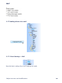
On the next page select the configuration path using the
profiles.
Select the profile „Network basic parameters“ and click on the
„Show profile“ button“.
20
W&T
The device now automatically displays the necessary menu
points for this profile. In the configuration menu click on the
entry „Network“.
Subject to errors and modifications
21
W&T
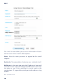
On the following page enter all the necessary network
parameters and then click on the „Logout“ button.
Clicking on the „Save“ button stores the settings in the device
and closes your configuration session. After the network
parameters are changed the device automatically performs a
restart.
22
W&T
The device is now ready to use in your network. For ease of
handling use the additional profiles for adapting the device to
your needs.
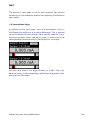
1.8 Smartphone Page
In addition to the start page, users of smartphones (such as
the iPhone) can make use of a special Web page. This is tailored
to the resolution of most phones. Here you can read the 2 analog measurement values and adjust them as necessary if the
corresponding device terminal is configured as an output.
You can also access this page directly as a URL: http://ipadresse/smart. A corresponding notification disappears after
pressing the OK button.
Subject to errors and modifications
23
W&T
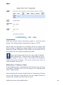
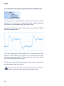
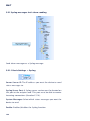
2 Graphical Representation of the Measurements
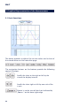
2.1 Basic functions
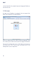
The device provides a table of the current values and a chart of
the stored values on the home.htm page.
The navigation buttons on the bottom provide the following
control functions.
Scrolls the chart to the right or left by the
size of the display interval.
Scrolls the chart right or left by one unit of the
x-axis.
Zooms in to the area of the chart indicated by
„Zoom +“ on the lower right edge.
24
W&T
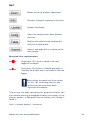
Zooms out to the previous zoom level.
Activates automatic updating of the chart.
Updates the display.
Opens the configuration menu beneath
the chart.
Displays the values current displayed in
the chart in table format.
Opens a new page with a snapshot of the
chart display.
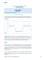
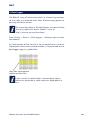
Measured value representation:
Large point: This value is stored in the data
logger of the device.
Small point: This value is a volatile one which is
used only for display and is not stored in the data
logger.
!
When exiting the zoom level these values
are lost. The connecting lines are only
displayed in the zoom level which
represents the memory.
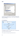
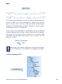
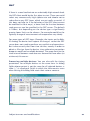
To print out the page containing the graphical display, you
must enable printing of background colors and images in the
Internet options. In Microsoft Internet Explorer this setting is
found in
Tools -> Internet options -> Advanced
Subject to errors and modifications
25
W&T
The design and configuration of the graphical display can be
varied. For additional information, see the section Configuring
the graphical display.
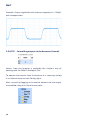
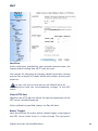
2.2 Config Menue
The following functions are available from the configuration
menu below the graphical display:
Start: Specify the starting time point for the x-axis
26
W&T
End: Specify the end time point for the x-axis.
Sensors: Turn individual sensors for the display on and off.
Polling Rate: Enter here the desired polling rate for the graphical
display. The device makes a new value available no sooner than
0.5 seconds. Entering a value of less than 0,.5 has no effect.
Extreme: If in the graphical display a zoom level is selected in
which a display point represents a measurement interval and
not an individual measuring point, this function is used to
display the maximum and miminum measured during this
interval. If the zoom level is selected so that every measurement
is displayed, this function has no effect. If the function is
turned off, the average of the displayed interval is displayed.
Show alarm monitor: Uses a bar graph to show whether the
alarm monitor is active or inactive for the respective alarm.
Apply: The changes made are immediately applied to the
graphical display.
Subject to errors and modifications
27
W&T
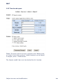
2.3 Table
This function is used to show the currently displayed values in
table format. As soon as not all the stored values can be
displayed, the following values for the sensor are shown in the
table:
Max:
Min:
Ø:
28
The maximum value in the displayed interval
The minimum value in the displayed interval
The average value of the displayed interval
W&T
3 Other Basic Settings
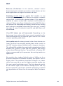
3.1 Configuring the port and device name
3.1.1 Text
Enter your personal descriptions in the fields and then click on
Temporary Storage.
Subject to errors and modifications
29
W&T
3.1.2 Ports
Port 1..2:
First enter a name and a descriptive text for the port and select
the measuring range for adapting the input wiring for your
measuring point (For model 57661 only: Measuring range
0..20mA or 4..20mA). To disable the port, select „Disconnect.“
Configuring the current input and output (Model 57661):
30
W&T
Configuring the voltage input and output (Model 57662):
Subject to errors and modifications
31
W&T
3.1.3 Port Config
In the Port-Config menu you can specify which values are
displayed when then input is in between 0% and 100% of the
scale . This entry also refers to the data logger and the output
value.
Example:
0% -> 10
100% -> 3000
If there is no input signal on the unit (0%), it will show a value
of „10“. If you set your output to the value „10“ the device will
output 0V or 0mA .
If there is an input signal of 10V or 20mA on the unit (100%),
the value „3000“ is displayed. If you set your output to the
value „3000“ so the device will output 10V or 20mA.
32
W&T
3.2 Calibration
The sensor can be calibrated using single-point and two-point
reference measurements and corresponding entries for offset
values.
In single-point compensation the entered offset value is added
to the measured value, whereas in two-point compensation a
straight line is calculated for compensating the entire
measuring range. The offset is allowed to be max. 20% of the
total range. The offset may be negative, but the full scale values
may not fall below the 0% mark.
For offset you enter the value to be added to the measured
value in order to reach the desired value.
To retain calibration setting, the user can store a comment text.
Subject to errors and modifications
33
W&T
3.3 Specifying Output Mode
You must specify which mode you want each individual output
to operate in. The corresponding configuration can be made
under Config >> Ports >> PortX >> Output Mode.
34
W&T
Output Mask:
Here you specify which operating mode is used for each
output. The factory default setting for all ports is HTTP.
Please note that for most of the modes you must make a few
other settings in addition to output mode, such as enabling the
operating mode. Additional information can be found in the
description for the respective operating mode.
!
Please note when using the active input that in Output
Mode “Output OFF” causes passive Input Mode to be set
for Config >> Ports >> Port x. This protects the hardware
from inadvertent damage. The active input must then be
selected again and saved.
Safety State / Timeout / Value
If no network activity is detected for the timeout time set here,
the Web-IO Analog-In/Out sets the outputs to a configurable
value (Safety Value).
After selecting the output modes click on Temporary Storage
to sent the settings to the device. Use the Logout button to
activate the settings and then click on Save.
Subject to errors and modifications
35
W&T
3.4 Compensation of the output controller (57662 only)
During the use of applications, which have a high entrance
capacity, it is necessary to compensate the voltage regulator
to prevent an overshooting of the output value.
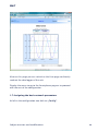
Example: Output regulation with entrance capacity of 100µF,
without compensation:
This overshooting can be avoided with a compensation value
between 0 and 1000. This value can be configured manually,
or determined automatically. The device adjusts two test pulses
with 80% amplitude at the output.
To start the automatic determination of the compensation click
on the button „send test pulses“.
1
Please make sure that no sensitive devices are attached
to the output to avoid inadvertent output levels.
36
W&T
„Send Testpulses, please wait ...“
After clicking the button the device begins with the automatic
compensation. The test pulses with a capacity of 100µF appear
as follows:
Value: The device enters the determined compensation value
automatically. This value is valid immediately. The value can
also be set manually. Subsequently, the desired value which was
present before the determination will be adjusted again.
Mode:
Auto adaptive enable: The device determines the compensation
at run-time. Here no compensation value must be registered.
The disadvantage here is in the fact that constantly changing
capacities must be measured first, until the initial value fits
again correctly.
Use saved value at power on: If this function is activated, the
adjusted compensation value is used immediately after starting
the device.
Subject to errors and modifications
37
W&T
Example: Output regulation with entrance capacity of•n 100µF,
with compensation:
3.5 HTTP - Controlling outputs in the browser (Control)
Access from the browser is probably the simplest way of
working with the Web-IO Analog-In/Out.
To operate the outputs from the browser it is necessary to log
in as Administrator or with Config rights.
After successfuly logging in the control elements for the output
are enabled using the Control menu point.
38
W&T
The Follow slider checkbox causes the selected output value to
be set as soon as the slide controller is released at a certain
point. At the same time the slide controller automatically
changes its position when the device changes its output value,
for example using TCP commands.
If the Follow slider checkbox is not selected, an input field and
a button appear which can be used to manually set the output.
The value in the input field can also be set using the slide
controller. The entered output value is set as soon as the Set
button is clicked.
!
Please note that control scaling has only limited function:
0..10 (#57662) or 0..20 (#57661) in configured scaling.
3.6 Basic Settings HTTP
Subject to errors and modifications
39
W&T
Properties of device regarding HTTP have to be configurated on
Config >> Devices >> Basic Settings >> HTTP.
Startup: Specify here which HTML page you want displayed
when the device starts up.
Enable: The device can, when polled using an HTTP-Get
command, also send along with the measured value a header
with the IP address and name of the device. Check the
corresponding box to enable this. If this function is disabled
only the actual measurement is sent.
The function GET HTTP enable is a special SAP application. If
enabled the connection is closed automatically after device
reply.
HTTP Port: You can use this port to access the device. The
factory default setting is the standard HTTP port 80. If you want
to use a different port, this may need to be explicitly names
when opening the page:
http://<ip address>:<PortNr>
For the usage of HTTP commands „GET /...“ please refer chapter
4 „Individual Measurement Polling“.
40
W&T
3.7 Basic Settings UDP
Subject to errors and modifications
41
W&T
In addition to TCP/IP commands the device can also reply to
UDP datagrams. Here you need to set the local Port you want
the device to listen to. The factory default setting is 42279. The
Remote Port default is AUTO for answering to Source Port.
In special cases Web-IO have to answer to defined port that is
not equal 0.
The Enable function turns on UDP.
The setting for the header which can be appended to the
measurement value also applies here.
3.8 BINARY - Socket programs with binary structures
The Web-IO Analog-In/Out provides two independent socket
accesses, Binary 1 and Binary 2, for binary data exchange. Both
can be used and configured independently of each other.
Whether the device should use the respective BINARY socket as
a TCP server, TCP client or UDP peer depends on the desired
application
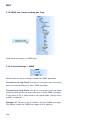
Here is an overview of applications and operating modes for
the Web-IO:
42
W&T
. Customer socket application (binary with password
protection)
. TCP-Server
. TCP-Client
. UDP-Peer
. Customer socket application which uses the same structure
as the W&T Digital- EA-Com-Server 50xxx.
. TCP-Server
. TCP-Client
. UDP-Peer
. Box-to-Box Master (with password)
. TCP-Client
. Box-to-Box Slave (with password)
. TCP-Server
. OPC-Device together with the W&T OPC-Server (with
password)
. TCP-Server
Binary socket access
In this section you will learn how the Web-IO Analog-In/Out can
be accessed from your own professional applications using
sockets with binary structures.
i
Box-to-Box and OPC device modes are covered in greater
detail in the next sections.
3.8.1 Specifying the operating mode
First you must specify whether the Web-IO Analog-In/Out will
be be used in your application as a TCP client, TCP server or
UDP peer.
Subject to errors and modifications
43
W&T
In the navigation tree select Config >> Device >> Basic Settings
>> Binary 1 if you want to configure the operation mode for
access through Binary 1.
m
Necessary access rights: Administrator
After selecting the desired mode and setting Enable Binary
send the setting to the Web-IO Analog-In/Out by clicking on
the Temporary Storage button.
For access from your own application programs the developer
is provided with two levels of the socket programming.
1. Socket Device (password protected access)
2. Compatible 50xxx (This mode is compatible with the binary
structure which was alrelady used by the older W&T Digital
I/O Com-Servers.)
Both access options use the same binary structures and differ
only in the absence of password protection in Compatible
50xxx mode.
3.8.2 The Web-IO Analog-In/Out as Socket-Server
To operate the Web-IO Analog-In/Out as a socket server, a few
additional settings must be made.
44
W&T
In the navigation tree select Config >> Device >> Basic Settings
>> Binary 1>> TCP Server.
m
Necessary access rights: Administrator
Local Port
The local port on the device is factory set to 49153. If your
application requires a different local port for the Web-IO, enter
the desired port number in the Local Port field.
Client HTTP Port
Is only relevant for OPC and Box2Box modes and specifies the
HTTP port on which a control line should open a connection to
the OPC server or slave box.
Unless otherwise specified, Port 80 should always be used here.
Binary Trigger
Enter here a hysteresis value for both ports which, when it is
reached or exceeded, should trigger sending of data to the
client application (important for event-triggered applications).
Subject to errors and modifications
45
W&T
Application Mode
Select here:
. Socket Device - If you want access to the Web-IO password
protected.
. Compatible 50xxx - If you want access to the Web-IO using
applications which were programmed for the older Digital
I/O Com-Servers. You can also use this mode for new
applications that do not require password protection.
i
A more detailed discussion of Box2Box Slave and OPC
Device modes can be found in the corresponding
sections.
After all your settings have been made, send them to the WebIO by clicking on the Temporary Storage button.
In addition, the ports used must be enabled for Binary Mode.
In the navigation tree select Config >> Ports >> Port X >> Output Mode and highlight the desired binary access.
m
Necessary access rights: Administrator
After all the entries have been made, send the setting by
clicking on the Logout button. Click on the Save button to
activate the settings.
i
46
All configuration possibilities shown for Binary 1
may also be used for Binary 2.
W&T
3.8.3 The Web-IO as Socket-Client
To operate the Web-IO as a socket client, a few additional
settings must be made.
In the navigation tree select Config >> Device >> Basic Settings
>> Binary 1>> TCP Client
m
Necessary access rights: Administrator
Local Port
The local port of the Web-IO is factory set to AUTO. If your
application requires a special local port for the Web-IO, enter
the desired port number in the Local Port field.
Server Port
Enter here the port number the server application should use
to receive the connection.
Subject to errors and modifications
47
W&T
Server HTTP Port
Is only relevant for Box2Box mode and specifies the HTTP port
on which a control line should open a connection to the slave
box.
Unless otherwise specified, always use Port 80 here.
Server IP Addr
Enter here the IP address of the server.
Server Password
A server password only needs to be entered if the Web-IO is
used as a Box-to-Box Master or needs to access a different WebIO as a TCP client in Server mode. More about this in the Boxto-Box section.
Inactive Timeout
Here a timer is configured. After the time expires, the Web-IO
closes the TCP connection. The value is entered in decimal and
in 100ms increments. The timer is reset during an active
connection when data are exchanged.
Example: The value 10 corresponds to one second. If no data
transfer is detected for one second, the Web-IO closes the
connection.
If no value is entered, automatic connection closing is
disabled..
Binary Trigger
Here you select the ports whose status change should act as a
trigger for opening the TCP connection and sending data to the
server (important for event-triggered applications).
Interval
If you want the status of the inputs to be sent cyclically to the
server application, you can enter here the interval in 100ms
increments.
Example: A value of 300 corresponds to 30 seconds.
48
W&T
1
Please note that for connections using fee-based dialup connections too small an interval may result in the
connection not being closed, in turn resulting in permanent
fees!
Mode
Select here:
. Socket device - If you want access to the Web-IO password
protected.
. Compatible 50xxx - If you want access to the Web-IO using
applications which were programmed fo the older Digital IO
Com-Servers. You can also use this mode for new
applications that do not require password protection.
More detailed information about Box2Box Master mode can be
found in the Box-to-Box section.
After all your settings have been made, send them to the WebIO by clicking on the Temporary Storage button.
In addition you must enable the used outputs for Binary mode.
Now in the navigation tree select Config >> Ports >> Port X >>
Output Mode and highlight the desired Binary access.
m
Necessary access rights: Administrator
Subject to errors and modifications
49
W&T
After you have made all your settings, send them by clicking
on the Logout button. Clicking on the Save button activates the
settings.
3.8.4 The Web-IO as UDP-Peer
To use the Web-IO as a UDP peer a few additional settings must
be made.
In the navigation tree select Config >> Device >> Basic Settings
>> Binary 1>> UDP Peer
m
Necessary access rights: Administrator
Local Port
The local port on the device is factory set to 45889. If your
application requires a different local port for the Web-IO, enter
the desired port number in the Local Port field.
50
W&T
Remote Port
Enter here the port number you want the UDP application to use
for receiving data when communicating with the Web-IO.
Remote IP Addr
Enter here the IP address of the communication partner.
Binary Trigger
Enter here the inputs whose change of state should be used as
the trigger for sending a UDP datagram (important for eventtriggered applications).
Interval
If you want the status of the inputs to be sent cyclically to the
communication partner, enter here the interval in 100ms
increments.
Example: A value of 300 corresponds to 30 seconds.
1
Please note that for connections using fee-based dialup connections too small an interval may result in the
connection not being closed, in turn resulting in permanent
fees!
Application Mode
In the configuration as UDP peer there is no difference between
Socket Device and Compatible 50xxx modes.
After all your settings have been made, send them to the WebIO by clicking on the Temporary Storage button.
In addition you must enable the used outputs for Binary mode.
Now in the navigation tree select Config >> Ports >> Port X >>
Output Mode and highlight the desired Binary access.
m
Necessary access rights: Administrator
After you have made all your settings, send them by clicking
on the Logout button. Clicking on the Save button activates
settings.
Subject to errors and modifications
51
W&T
3.8.5 Password protection
As already mentioned earlier, the Web-IO enables you in TCP
server mode to protect access through the application using a
password.
Before the actual connection to the Web-IO is opened, the
BinInfo structure defined here must be sent over a separate TCP
connection to the HTTP port (factory set to Port 80) on the WebIO.
For the reply the Web-IO also uses the structure BinInfo.
BinInfo
(PC <-> Web-IO
BYTE[n]0
WORD
BYTE
BYTE
LONG
WORD
WORD
HTTPlogin
dummy
type
subtype
srcip
srcport
destport
n = 14 bytes + password
always 0
type of request
additional information
source ip-address
source port
destination port
The individual variables of the structure are filled in as follows:
HTTPLogin[n]
A byte field or string consisting of a login string and the Administrator password.
GET /bin?LPW=<Administator Passwort>&
52
W&T
n stands for the number of bytes used and corresponds to 14
+ the length of the password. The length of the password is
limited to 31 characters.
In the reply from the Web-IO HTTPLogin is always 8 characters
in length and contains the following string:
GET /bin
Dummy
Slash between the ASCII and the binary section of the structure.
Is always = 0x00
Type
Determines the type in which Binary mode is used.
The application must enter 0x10 here in order to open a TCP
connection.
In its reply the Web-IO enters
0x02 if the connection request was accepted
0x03 if the connection request was denied.
SubType
Provides more details about the status of the connection
request.
The application always sends 0x00.
The Web-IO replies with
0x01
BINSUBTYPE_OK,
// connection accepted
0x02
BINSUBTYPE_NO_ACCESS,
// other sesion active
0x04
BINSUBTYPE_WAIT,
// OK after time out time (circa 3s)
0x07
BINSUBTYPE_PW_MISMATCH,
// wrong password
0x08
BINSUBTYPE_DEST_PORT_MISMATCH, // wrong destination port
0x09
BINSUBTYPE_MODUS_MISMATCH,
// wrong mode
Subject to errors and modifications
53
W&T
If 0x01 or 0x04 was received, the actual data connection can
be opened.
SrcPort
The client application alwlays enters a 0 here.
The Web-IO returns here the opened server port (e.g. 49153 for
Binary 1). If the login attempt has failed, the Web-IO enters 80.
DestPort
The client application enters here which port will be used for
the connection (e.g. 49153 for Binary 1 or 49154 for Binary 2).
The Web-IO always returns 0.
The connection through which the BinInfo structure was
transmitted is automatically closed by the Web-IO.
3.8.6 BINARY - The IO structures
To enable simple communication between the user program on
the computer and the Web-IO, there are a limited number of
structures (variable fields) which define the format and content
of the data exchanged between the user program and the WebIO.
IO structures are provided for the following functions:
. Reading the inputs
. Setting the outputs
. Parameterizing the cyclical and automatic messaging when
there is a status change
The user program uses the easy to use socket4 interface
(Windows: WinSock, UNIX, Linux: Berkley Sockets) for
exchanging data in the form of these IO structures with the
Web-IO over the network via TCP/IP.
The IO structures do not depend on the network protocol used
(TCP or UDP).
54
W&T
Socket-Interface
UDP-/TCP-Header
IP-Header
IO-Structures
UDP-/TCP-Data
IP-Data
Ethernet-Data
Ethernet-Header
Which of the two protocols are used, UDP or TCP, depends on
the type of application. Both protocols offer advantages and
disadvantages which must be considered depending on the
application you want to create.
i
Help with socket programming including the basics of
TCP/IP can be found in a short and clear form in our
manual „Ready in 1 day for TCP/IP Sockets“. Program examples
for client/server applications under TCP/IP are located on our
homepage at http://www.wut.de.
3.8.7 Definition of the IO structures
To be able to unambiguously identify and process the contents
of a packet, in BINARY mode all the data must be sent to the
Web-IO in the form of these IO structures regardless of whether
50xxx-compatible or Socket Client mode is used..
All structures begin with the same header which consists of the
following 4 WORDS (16bit_Integer):
Structure-Header
WORD
WORD
WORD
WORD
send_sequence
rec_sequence
struct_type
length
always 0
always 0
identifies the structure
length of the structure in bytes
send_sequence, rec_sequence
For compatibilty reasons with respect to older Digital I/O ComServers send_sequence and rec_sequence are provided but not
used. Both values are always 0.
struct_type
The value struct_type identifies which structure is being used.
Both the PC application and the Web-IO decide when the data
are received how the structure should be processed based on
the value struct_type.
Subject to errors and modifications
55
W&T
length
length indicates the total length of the structure in bytes, i.e.
including the first 4 WORDs.
The result is the following packet structure:
WORD
WORD
WORD
WORD
Variable
...............
Structure buildup
1
send_sequence
rec_sequence
struct_type
length
...............
...............
always 0
always 0
identifies the structure
length of the structure in bytes
depends on the function
additional variables
Note: The following applies for all IO structures.
A WORD corresponds to 16bit_integer (unsigned)
A BYTE corresponds to one byte (8 bits)
A LONG corresponds to a 232bit_integer (unsigned)
Hexadecimal format: 0x in front of the value
1
When sending and receiving, the following applies for
all structure variables: Low-Byte first.
The following structure
Example
WORD
WORD
WORD
WORD
send_sequence
rec_sequence
struct_type
length
0x0000
0x0000
0x0001
0x0008
would look as follows when sent on the network:
send_sequence
low byte high byte
00
00
rec_sequence
low byte high byte
00
00
struct_type
low byte high byte
01
00
length
low byte high byte
08
00
3.8.8 Working with the IO structures
In the next section we will explain the individual structures and
the corresponding values of the variables send_sequence,
rec_sequence, struct_type and length, which are used to begin
each packet.
56
W&T
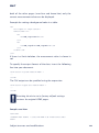
IO-Structure ReadRegister
Sending this structure to the Web-IO causes it to send the
status of the port to the user program. The packet consists only
of these four WORDs. This structure is used only by the user
program, and the Web-IO always responds by sending the
structure AnalogRegisterState.
ReadDiagnosis
(PC -> Web-IO)
WORD
WORD
WORD
WORD
send_sequence
rec_sequence
struct_type
length
always 0
always 0
0x00D1
0x0008
IO-Structure AnalogRegisterState
The Web-IO Analog-In/Out uses this structure to lsend the
state of both ports. This structure is sent when the user program has sent the structure ReadRegister to the Web-IO, or
when this structure was used to set an output value.
AnalogRegisterState
(Web-IO <-> PC)
WORD
WORD
WORD
WORD
LONG
LONG
LONG
send_sequence
rec_sequence
struct_type
length
word_anz
Port 1
Port 2
always 0
always 0
0x01B8
0x0014
2
Port1 State (in 1/1000 %)
Port2 State (in 1/1000 %)
This structure is also used for sending the output value of the
port for the Web-IO Analog-In/Out. When the user program
sends this structure to the Web-IO, the Web-IO sets the outputs
according to the value sent on Port 1 and Port 2. Here the value
is not transmitted in the configured units, but rather always in
1/1000 % of the current or voltage present. An output value of
15.4mA must be sent as 77000 x 1/1000 %, or 0x012CC8.
When the Web-IO sends this structure to the user program, Port
1 and Port 2 have the value correspolnding to the input state.
Die IO-Struktur AnalogSingleRegister
This structure is used for sending the output value to a single
port of the Web-IO Analog-In/Out. The procedure is identical to
AnalogRegisterState.
Subject to errors and modifications
57
W&T
AnalogSingleRegister
(Web-IO <-> PC)
WORD
WORD
WORD
WORD
LONG
LONG
LONG
send_sequence
rec_sequence
struct_type
length
word_anz
channel
value
always 0
always 0
0x01BB
0x0014
1
0 or 1
in 1/1000 %
IO structure Send Mode
This structure determines the trigger conditions the Web-IO
Analog-In/Out uses to send the state of the ports to the user
program. The trigger can be configured for state changes on
both ports. The respective hysteresis for the trigger must be
set in the Web configuration.
WORD
WORD
WORD
WORD
WORD
WORD
SendMode
(PC -> Web-IO)
send_sequence
rec_sequence
struct_type
length
input_trigger
interval
always 0
always 0
0x0010
0x000C
0x0000 - 0x0003
Intervall data packets in 100ms
The following combinations can be configured as input_trigger
variables:
0x0000
0x0001
0x0002
0x0003
Port 1
off
on
off
on
Port 2
off
off
on
on
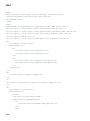
IO structure ReadDiagnosis
If the Web-IO detects a communications or system error, the
error is listed on the HTML page diag and can be read from the
browser. Since error management via browser is not always
available for program-controlled applications, the error status
of the Web-IO can be polled using the structure ReadDiagnosis.
58
W&T
ReadDiagnosis
(PC -> Web-IO)
WORD
WORD
WORD
WORD
send_sequence
rec_sequence
struct_type
length
always 0
always 0
0x00D1
0x0008
In reply the Web-IO sends a Diagnosis type structure.
IO structure Diagnosis
The Web-IO sends the Diagnosis structure in reply to the
ReadDiagnosis structure.
Diagnosis
(Web-IO -> PC)
WORD
WORD
WORD
WORD
LONG
LONG
LONG
LONG
LONG
send_sequence
rec_sequence
struct_type
length
word_anz
diag_error_count
diag_errorbits0
diag_errorbits1
diag_errorbits2
always 0
always 0
0x00D0
0x001C
in this version 4
quantity of pending errors
binary error encoding
The variable diag_error_count returns how many different
errors are currently in the error log. The Web-IO differentiates a
variety of different error states, whereby each set bit in the variables diag_errorbits0, diag_errorbits1 and diag_errorbits2
stands for an error type.
The exact text description can be opened using TCP Port 80.
IO structure ClearDiagnosis
This structure is used to clear the error log in the Web-IO.
ClearDiagnosis
(PC -> Web-IO)
WORD
WORD
WORD
WORD
send_sequence
rec_sequence
struct_type
length
always 0
always 0
0x00D2
0x0008
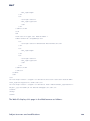
IO structure Options
This structure is used to set certain options in the Web-IO. 32
bits are available for this in the options variable.
Options
(PC -> Web-IO)
WORD
WORD
WORD
WORD
LONG
LONG
send_sequence
rec_sequence
struct_type
length
word_anz
options
always 0
always 0
0x01F0
0x0010
in this version 1
binary option encoding
In the current version of the Web-IO only Bit 0 in the options
variable
is errors
used. and modifications
Subject to
59
W&T
3.9
Box-to-Box (tunneling measurement network)
In this mode the inputs of a Web-IO Analog are transferred to
the outputs of a second Web-IO. In this way you can for
example send signals from one location to another over a WAN
connection.
The values are sent as a percentage. This means a model
#57662 can send (“convert”) voltage values of 0…10V to a
model #57661 with current values of 0…20mA and vice-versa.
Feature: It is also possible to tunnel an analog value to a
receiving Web-IO from two different locations.
With Box-to-Box connections a Web-IO assumes the function
of the Master. The second Web-IO operates as a Slave. The Slave
(Server) waits for the Master (Client) to open the connection.
The device which physically reads the analog values can be
configured as a slave or a master. The same applies to the
device which then outputs the analog values.
Note for safety-critical applications: Alarms can be defined in
both devices in case the Box-to-Box connection is interrupted.
It should then be possible for at least one of the devices to
send a message.
Both the Master and the Slave Web-IO need to be
correspondingly configured.
60
W&T
3.9.1 Configuring the Slave Web-IO (Server)
m
Necessary access rights: Administrator
In the navigation tree of the Slave Web-IO select Config >>
Device >> Basic Settings >> Binary 1
For Operation Mode set TCP-Server mode and activate Enable
Binary 1.
Then click on the Temporary Storage button to send the
changes to the Web-IO.
Subject to errors and modifications
61
W&T
Now in the navigation tree select: Config >> Device >> Basic
Settings >> Binary1 >> TCP-Server
Local Port
Unless your network administrator has informed you otherwise,
the factory default set Port 49153 may be used.
One reason for changing the factory default set local port may
be for example a fireweall which permits access only to a
particular port.
1
In any case the set local port on the Slave must be
identical to the Server Port entry for the Master.
Client HTTP Port
Specifies which HTTP port to be used for opening the control
connection to the Master box.
Unless otherwise specified, always use Port 80 here.
Binary Trigger
Here you activate the inputs which are to set the corresponding
outputs on the Master.
i
The Web-IO Analog-In/Out allows simultaneous access to
the input from various modes.
This means for example that the inputs which control the
outputs on the Master Web-IO can at the same time be read out
over HTTP.
Application Mode
Select Box2Box Slave
After all the parameters have been entered, confirm by clicking
on the Temporary Storage button.
Now in navigation tree: Config >> Ports >> Port 1 >> Output
Mode
62
W&T
Activate the outputs to be set by the corresponding inputs on
the Slave for Binary 1 and confirm by clicking on the Temporary
Storage button.
The outputs activated for Box-to-Box are no longer accessible
for other modes.
Next the new settings still need to be activated. Use the Logout
button or select Config >> Session Control >> LogOut.
3.9.2 Configuring the Master (Client)
m
Necessary access rights: Administrator
In the navigation tree select: Config >> Device >> Basic Settings
>> Binary1
For Operation Mode select TCP-Client mode.
Subject to errors and modifications
63
W&T
Then click on the Temporary Storage button to the Web-IO.
Now in the navigation tree select: Config >> Device >> Basic
Settings >> Binary1 >> TCP-Client.
The following parameters must be entered:
64
W&T
Local Port
Unless otherwise specified by your network administrator, the
factory default setting AUTO can be used.
ServerPort
Here the Local Port for the Slave must be entered. Here again
the basic setting 49153 can be used unless otherwise specified
by the network administrator.
i
Local Port and Slave Port do not necessarily have to be set
the same as the factory default settings.
One reason for changing the factory default settings for Local
and Slave Port may be for example a fireweall which permits
access only to a particular port.
Server HTTP Port
Specifies the HTTP port on which the control connection is to
be opened to the Slave box.
Unless otherwise specified, always use Port 80 here.
Server IP Addr
Enter here the IP address of the Web-IO to be used as a Slave.
Server Password
Here the administrator password of the Slave-IO is entered. If
no password has been assigned for the Slave, this field remains
blank.
Inactive Timeout
This parameter has no function in Box-to-Box mode, since a
permanent connection is desired.
Binary Trigger
Activate here the inputs which the corresponding outputs
should set for the Slave.
i
The Web-IO Anaog-In/Out allows simultaneous access
to the inputs from various modes...
Subject to errors and modifications
65
W&T
This means for example that the inputs which control the
outputs on the Master Web-IO can at the same time be read out
over HTTP.
"Input Trigger" allows sending based on an input change. Use
“Hysteresis” to specify how great the change should be in order
for a new value to be sent.
Interval:
If no interval is entered, the state of the inputs is sent to the
outputs of the other respective Box-to-Box partner whenever
there is a change. By entering an interval the state is also sent
cyclically even when there is no change.
1
If two locations are connected to each other over a feebased ISDN line, use of an interval is discouraged since
the ISDN connection may either be never disconnected or often
reopened depending on the timeout and interval.
i
Recommendation for fast response to changes with the
least possible network load: Set interval to 2s and enable
Input Trigger with a hysteresis value which allows relevant
signal changes to be detected.
Application Mode
Select Box2Box Master
After all the parameters have been entered confirm by clicking
on the Temporary Storage button.
Now in the navigation tree select: Config >> Ports >> Port 1 >>
Output Mode
66
W&T
Activate here the outputs which are to be set by the
corresponding inputs on the Slave for Binary 1 and confirm by
clicking on the Temporary Storage button.
In contrast to the inputs, the outputs activated for Box-to-Box
mode are no longer accessible for other modes.
Now the new settings still need to be activated. Use the Logout
button or select Config >> Session Control >> LogOut.
After clicking on the Save button all the settings are updated in
the Web-IO and the start page is reopened in the default user
mode. The Master Web-IO attempts then to open a connection
to the Slaqve Web-IO. All functions described here for Binary 1
can of course also be used under Binary 2. For example a WebIO A in the Binary 1 area can be configured so that Input 1
operates Box to Box with a Web-IO B. In the Binary 2 area Input
2 can then be configured so that it works together Box-to-Box
with another Web-IO.
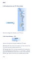
3.9.3 Determining Box-to-Box connection status
m
Necessary access rights: Administrator
The connection status of a Box-to-Box connection can be
queried using the navigation tree under Diag >> Test >> Output Config.
Subject to errors and modifications
67
W&T
Here you are shown in which mode the individual inputs are
currently working. In addition the current status of a Box-toBox connection is displayed in the footer of the Web page.
3.9.4 Quitting Box-to-Box mode
Box-to-Box mode only for the Master
m Necessary access rights: Administrator
Quitting Box-to-Box mode should always be done by
configuring the Master correspondingly. Master and Slave WebIO must be connected in the network. In the navigation tree
select des Masters: Config >> Device >> Basic Settings >>
Binary1 >> TCP Client and delete the entry for Server IP Addr.
Also set Application Mode to Socket Client.
Confirm by clicking on the Temporary Storage button.
Then set under Config >> Device >> Basic Settings >> Binary1
the Operation Mode to TCP Server.
Confirm by clicking on the Temporary Storage button.
Now in the navigation tree for the Master select: Config >> Ports
>> Port X >> Output Mode and set the outputs you want to
operate Box-to-Box to HTTP.
Confirm by clicking on the Temporary Storage button. Now the
changed settings still need to be activated. Use the Logout
button or select Config >> Session Control >> LogOut.
After clicking on the Save button all the settings are updated in
the Web-IO and the start page is reopened in the default user
mode.
Quitting Box-to-Box mode for the Slave Web-IO
m Necessary access rights: Administrator
68
W&T
In the navigation tree select des Slave: Config >> Device >>
Basic Settings >> Binary1 >> TCP Server and set Application
Mode to Socket Device.
Confirm by clicking on the Temporary Storage button.
In the navigation tree select Config >> Ports >> Port X >> Output Mode and set the outputs which are no longer to operate
Box-to-Box to HTTP.
Confirm by clicking on the Temporary Storage button. Now the
changed settings still need to be activated. Use the Logout
button or select Config >> Session Control >> LogOut.
After clicking on the Save button all the settings are updated in
the Web-IO and the start page is reopened in the default user
mode.
3.9.5 Quitting Box-to-Box mode only for the Slave Web-IO
If the Master is no longer available, for example because there
is no network connection but you still want to deactivate Boxto-Box mode for the Slave, in the navigation tree select
Config >> Session Control >> LogOut.
The configuration frame contains an addition button called
Stop Box2Box Slave.
If this button is not displayed, first click on the Reset button.
The Web-IO is restarted.
Subject to errors and modifications
69
W&T
After logging in again and opening Config >> Session
Control >> LogOut the Stopp Box2Box Slave button will be
shown. Clicking on the button resets the Slave to Box-to-Box
mode.
3.9.6 Preconfiguring Box-to-Box for another network
You can configure Box-to-Box mode from your desk. Then carry
out the following steps (Master = Client, Slave = Server):
Master: Use Binary disable to close the connection, then save.
Now the slave is ready to accept a new connection.
Slave: Set network address to the destination network, then
save. Now the device is no longer accessible to you after a reset.
Master: Binary enable, TCP-Client enter new slave IP address. Set
network address to the destination network, then save. Now the
device is no longer accessible to you after a reset.
When changing the IP address please be sure you are also using
the correct subnet mask and gateway address.
Now both devices will automatically connect to each other in
the new network.
70
W&T
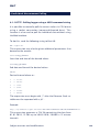
3.10 Modbus TCP
Modbus TCP is a software interface for address-based access
to process data. The W&T Web-IOs work as Modbus servers
(slaves) which can be controlled by a variety of Modbus TCP
controllers (clients).
Modbus TCP access allows you to read the analog in- and
outputs. You can also set outputs.
The Web-IOs are not intended to be configured using Modbus.
This is done from the Web browser.
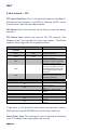
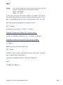
3.10.1 Configuration for Modbus TCP access
m
Required access rights: Administrator
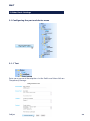
From the Web-IO navigation tree select Config >> Device >>
Basic Settings >> Binary 1.
For Operation Mode set TCP-Server mode and check Enable
Binary.
Subject to errors and modifications
71
W&T
Then click on the Apply button to send the changes to the
Web-IO.
In the navigation tree select: Config >> Device >> Basic Settings
>> Binary 1 >> TCP-Server.
Local Port: For use in the normal Modbus TCP environment the
local port on the Web-IO should be set to 502. This can be
selected only in a binary channel. If you need to access the
device with 2 clients, you must select a different port for Binary
2.
Client HTTP Port: With Modbus TCP access this port is not
used and can remain set to the default value.
Input Trigger: The input triggers must not be activated for
Modbus TCP mode, and are turned off when selecting Modbus
as the Application Mode.
Application Mode: Select Modbus.
72
W&T
After you have entered all the parameters, confirm by clicking
on the Temporary Storage button.
From the navigation tree select: Config >> Ports >> Port 1 >>
Output Mode.
Here you select the analog output as Binary 1 which you want
to be controlled by Modbus. Confirm by clicking on the
Temporary Storage button.
Now you must still enable the new settings. Use the Logout
button or menu sequence Config >> Session Control >> LogOut.
After clicking on the Save button all the settings are updated in
the Web-IO and the start page is reconstructed. The Web-IO can
now be accessed by the Modbus client.
Subject to errors and modifications
73
W&T
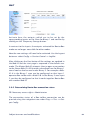
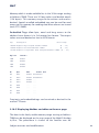
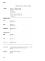
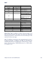
3.10.2 Modbus variables for Web-IO Analog In/Out
All address information is in hex format.
There are various Modbus memory ranges for the Web-IO:
.
.
.
.
Bit range (starting at Address 1000 or 1800)
16-bit range (starting at Address 2000),
32-bit range (starting at Address 5000, 6000 or 7000),
8-bit range (Exception Status, no address).
Addressing is done in the bit-range, i.e. 1 bit requires an
address. In the 16-bit and 32-bit range addressing is by the
word (2 bytes).
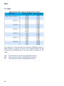
The analog inputs are located in the 32-bit range starting at
Address 5036 (example for 5766x: 5036 and 5038). The values
are in percent with 3 places following the decimal point and are
considered relative..
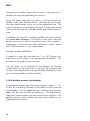
Value
0%
1°%
1%
10%
65.5%
65.5%
100%
120%
dec.
0
10
1,000.
10,000
65,535
65,536
100,000
120,000
hex.
0x0000 0000
0x0000 000A
0x0000 03E8
0x0000 2710
0x0000 FFFF
0x0001 0000
0x0001 86A0
0x0001 D4C0
4-20mA
4
4,0016
4.16
5,6
14.4856
14.4857
20
23.2
0-10V
0
0.001
0,1
1
6.55
6.55
10
12
The analog outputs are located in the 32-bit range starting at
Address 5046 (example for 5766x: 5046 and 5047). The values
(see above) are in percent with 3 places following the decimal
point.
The alarms are located in the bit range starting at Address
1040 (example for 5766x: 1040 bis 1048), in the 16-bit range
at 2004 and in the 32-bit range at Address 5004. The alarm
trigger bits lie in the bit range starting at Address 1800.
74
W&T
The Exception-Status is located in the bit range starting at
address 1060, in the 16-bit range at 200D (Low Byte).
Alternately the Exception Status is read out using the function
code 0x07.
The Configuration-Status is located in the bit range at Address
1068, in the 16-bit range at 200D (High Byte).
The Diagnostics-Status (number of errors) is located in the 16bit range at 2006, in the 32-bit range at 504A.
The Diagnostics Status Bits lie in the 16-bit range starting at
2007, in the 32-bit range starting at 504C. #5766x allows 64
error messages.
The Device Identification is by serial number (starting at
6000) and Mac address (starting at 6004).
Available memory range, which the device provides for any
Modbus client, lies in the 32-bit range starting at Address 7000.
3.10.3 Modbus-TCP device behavior
When reading data (memory ranges) which were not defined for
the device, the device returns „0“.
When writing inputs the device responds with an error message.
The analog output values are double words (4 bytes). These
should be written in one pass, i.e. preferably use function code
0x10 for writing. When accessing the values with function code
0x06 bear in mind that two words need to be written.
1
If the two words are written individually, there may be
jumps in on the analog output.
Note also: For analog values which are impermissibly high
(> 120%) or low (<0%), the value is accepted without an error
message and the permissible limit (see values table) is set.
Subject to errors and modifications
75
W&T
Diagnostics status writing of the Master: Reset (corresponds to
„Delete Report“) - regardless of the written value.
1
At present the configuration byte is 0, i.e. only Modbus
and Big Endian are supported. Others (JBUS, LIttle
Endian) are available on request.
3.10.4 Modbus - Alarm triggering incl. special memory
An alarm trigger bit in the bit memory range can be used to
trigger individual device alarms with the rising edge. The bits
are located starting at Address 1800 (Alarm 1). While the bit is
set the alarm is active. Resetting the corresponding bit also
clears the alarm. The Modbus alarm can be ORed with the other
triggers in the alarm.
The device provides memory (starting at register 7000) for free
use to report and visualize states in the Modbus TCP using the
Web-IO network services. This allows the Modbus client to save
any values (e.g. calculation results, states, measurement values
from other Modbus clients) to this memory. The client
determines when these values are passed along via alarm. One
alarm trigger bit (starting at register 1800) is available per
alarm. As long as the bit is set the alarm is active.
The time window function in the alarms can be combined with
the Modbus alarm trigger bit. For more information about this,
see the description under „Alarms - CRON services“. The output
functions can also be used for example for sensor alarms, and
are described after the alarms in this manual.
76
W&T
Memory which is made available lies in the 32-bit range starting
at Address 7000. These are 32 long values and double words
(128 bytes). This memory range can be written and read as
desired. Special so-called embedded tags can be used for read
access to this memory for sending data when alarms are issued
(mail, FTP, SNMP).
Embedded Tags allow byte, word and long access to the
address base. Access is in 2-character hex format. The output
values are send decimal or hex in ASCII format.
Tag
Description
Value range
<rbsHH> Register Byte signed decimal number
(0 .. 7F)
<rwxHH> Register Word hexadecimal number
(0 .. 3F)
<rluHH> Register Long/Double Word unsigned decimal number (0 .. 1F)
Register
Contents
7000
0x8182
7001
0x8384
7002
0x8586
7003
0x8788
No.
Byte
Word
00
0x81
0x8182 0x81828384
Double word
01
0x82
0x8384 0x85868788
02
0x83
0x8586 ...
03
0x84
0x8788 ...
04
0x85
...
...
05
0x86
...
...
06
0x87
...
...
07
0x88
...
...
Free texts and embedded tags can be mixed as desired in the
mail or FTP texts.
3.10.5 Displaying Modbus variables on the user page
The data in the freely usable memory range starting at Address
7000 can be displayed on the user page of the Web-IO Analog
In/Out. The procedure is similar to the familiar one for
Subject to errors and modifications
77
W&T
displaying an analog measurement value: <w&t_tags=m1>.
Likewise the tags are applicable to e-mail etc.
Using the above tags you can access the free memory as
follows: <w&t_tags=modbus:rbxHH>, whereby the syntax after
the colon corresponds to the syntax for embedded tags. This
means each byte can be read by the byte. The memory can be
read out by the word or in double words. Big Endian format is
used:
In addition, by using GET /modbusreg?PW=& you can read out
the entire data contents (128 bytes) at one time. Here the
device constructs an ASCII string which starts with „modbus“,
followed by „;“ and the data as ASCII characters (1 byte is shown
with 2 ASCII characters.), also separated by „;“.
Example: „modbus;00;00;00;...“
If „modbus“ is read, but then after the „;“ an „OFF“ follows, this
indicates that the device is not configured for Modbus. This
criterion can be used on the user page.
The user page can be adapted for the browser so that the
stored data can be displayed as desired. By adapting the
function CommandLoop() and updateDisplay(ReceiveStr) you
can refresh the Modbus values cyclically.
3.10.6 Modbus memory distribution
In the following tables you can see the memory ranges (1-, 16-,
32-bit) for the Web-IO Analog In/Out which can be accessed
using Modbus TCP. The green columns indicate which function
codes can be used to read the addresses. The red columns
show the function codes used for writing to the registers. The
yellow column shows which and how many elements are
supported by the device.
78
W&T
Memoryregion
MB-Startaddress
[hex]
Read m. FC / Read m. FC / Write m. FC /
Port access Block access Port access
Write m. FC
/ Block
access
5766x
Bit
Definition
Alarm- / Report-Status
(1-8)
Alarm- / Report-Status
(9-16)
1048
1,2
-
-
-
9
Bit
Exception-Status
1060
1,2
-
-
-
Bit
Bit
Bit
Bit
Bit
Bit
Bit
Bit
Bit
Conf.-Status
Alarm-Trigger 1
Alarm-Trigger 2
Alarm-Trigger 3
Alarm-Trigger 4
Alarm-Trigger 5
Alarm-Trigger 6
Alarm-Trigger 7
Alarm-Trigger 8
1068
1800
1801
1802
1803
1804
1805
1806
1807
1,2
1,2
1,2
1,2
1,2
1,2
1,2
1,2
1,2
-
5
5
5
5
5
5
5
5
15
15
15
15
15
15
15
15
Exc. 0-7
Conf-St.
0-7
1
2
3
4
5
6
7
8
8Bit
Exception-Status
Alarm- / Report-Status
(1-16)
Diagnose-Status
(Anzahl Fehler)
Diagnose-Status (0-15)
Diagnose-Status (1631)
Diagnose-Status (3247)
Diagnose-Status (4863)
Diagnose-Status (6479)
Exception-Status (low
byte) + Conf.-Status
(high byte)
-
-
7
-
-
x
Bit
16Bit
16Bit
16Bit
16Bit
16Bit
16Bit
16Bit
16Bit
Memoryregion
32Bit
32Bit
32Bit
32Bit
32Bit
32Bit
32Bit
32Bit
32Bit
32Bit
32Bit
32Bit
32Bit
32Bit
32Bit
32Bit
32Bit
32Bit
32Bit
32Bit
32Bit
32Bit
32Bit
32Bit
32Bit
32Bit
32Bit
32Bit
Definition
Alarm-/Report-St.(1-32)
AI 1
AI 2
AO 1
AO 2
Diagnose-Status (Error
quantity)
Diagnose-Status (0-31)
Diagnose-Status (3263)
Diagnose-Status (6495)
Serial number
Mac-address
Memory 0
Memory 1
Memory 2
Memory 3
Memory 4
Memory 5
Memory 6
Memory 7
Memory 8
Memory 9
Memory 10
Memory 11
Memory 12
Memory 13
Memory 14
Memory 15
Memory 16 .. 31
1040
1,2
-
-
-
1-8
2004
-
3, 4
-
-
1-9
2006
2007
-
3, 4
3, 4
-
6, 16
-
0-x
0-15
2008
-
3, 4
-
-
16-31
2009
-
3, 4
-
-
32-47
200A
-
3, 4
-
-
48-63
200B
-
3, 4
-
-
64
-
0-7, 815
200D
MB-Startaddress
[hex]
5004
5036
5038
5046
5048
-
3,4
-
Read m. FC / Read m. FC / Write m. FC /
Port access Block access Port access
3, 4
3, 4
3, 4
3, 4
3, 4
-
Write m. FC
/ Block
access
5766x
1-9
1
2
6,16
1
6,16
2
504A
504C
-
3, 4
3, 4
-
6, 16
-
0-x
0-31
504E
-
3, 4
-
-
32-63
5050
6000
6004
7000
7002
7004
7006
7008
700A
700C
700E
7010
7012
7014
7016
7018
701A
701C
701E
7020
-
3, 4
3, 4
3, 4
3, 4
3, 4
3, 4
3, 4
3, 4
3, 4
3, 4
3, 4
3, 4
3, 4
3, 4
3, 4
3, 4
3, 4
3, 4
3, 4
3, 4
-
6, 16
6, 16
6, 16
6, 16
6, 16
6, 16
6, 16
6, 16
6, 16
6, 16
6, 16
6, 16
6, 16
6, 16
6, 16
6, 16
6, 16
64
OK-Nr.
Eth-Nr.
0
1
2
3
4
5
6
7
8
9
10
11
12
13
14
15
16-31
Subject to errors and modifications
79
W&T
3.11 OPC - Standardized access
OPC (OLE for Process Control) is a software interface for
accessing process data based on OLE technology from
Microsoft.
Application programs such as visualization systems which use
this interface are called OPC clients. On the opposite side of
the interface are OPC servers. These are device drivers which
represent certain hardware in abstract form as a set of OPC variables.
The OPC server used here implements the specifications OPC
Data Access 2.0 and Alarms & Events. The server controls
devices in the W&T Web-IO product families, but also serial
Com-Servers and the older Digital I/O Server.
In terms of the architecture this is a system service running in
the background and a monolithic application which contains
the operating elements for configuration and diagnostics.
3.11.1
Installing the OPC-Server
The OPC server can be found on the product CD / DVD or on
included with the Web-IO, in the Web-IO Digital section.
On our Web site www.WuT.de you will find at left the
„Article number search“ function. Enter here for example
article number 57661, select „Tools“ from the field below
and click on „Go“. On the page that then opens select the link
„OPC-Server“.
g
For ease of downloading the required files are compressed in a
Zip file. Save the extracted file in any desired directory on your
hard drive (e.g. C:/Temp). Start the setup program by for
example selecting Run from the Start menu and then entering:
„C\Temp\opc_en.msi“ (choose the version for your language).
This installs and registers the OPC server on your computer.
80
W&T
The OLE server name which OPC clients will need to specify later
in order to connect to the server is: Wiesemann-Theis.NetworkIO. The OPC server starts automatically upon such requests. To
configure the server you can also run it manually. A
corresponding entry W&T OPC-Server Version 4 can be found
in the Start menu under „Programs.“
3.11.2 Uninstalling
You can remove the OPC server using the control panel
component „Software.“ It is listed there under OPC-Server for
network-I/O devices Version 4.
3.11.3 Configuring
First start the OPC server. For normal installations you will find
the corresponding start icon on your Windows interface under
Start >> Programs >> W&T OPC-Server Version 4.
Click on the Web-IO icon or in the menu on Device >> New I/O
device.
The following window opens:
Subject to errors and modifications
81
W&T
Host name or IP address: Must agree with the IP address which
was assigned to the unit. If there is also a DNS name for the
address, you can also use this instead of a number
combination.
HTTP port: Should normally be 80. The port number entered
here is also used for opening the external browser („WebBrowser“ button“).
Device type: In case of doubt the „Identify“ function can help
to select the proper type here. Some input fields with unneeded
parameters may be deactivated after a selection is made.
Passwort: Here you can enter the Config or the Administrator
password which was specified for the unit.
TCP Port: The factory preset for Port is 49153. For the Web-IO
Analog In/Out check the corresponding setting in the Web
menu of the unit.
OPC Device name: All OPC variables for a device begin with a
common (and unique) name component which you can specify
here.
Adjust timing: The amount of network traffic between the OPC
server and devices depends essentially on the behavior of the
OPC client: The more frequently a client requests updating of
DA items, the more data must be sent over the network.
82
W&T
If there is a need to eliminate an undesirably high network load,
the OPC client would be the first place to start. There you could
select any unnecessarily high update rate and choose not to
subscribe to any OPC items which are not really essential. If
this does not help (or if the behavior of the OPC client cannot
be modified in these ways), a lower limit for the time between
read accesses can be specified in the OPC server. The default
is 100ms, but depending on the device type a significantly
greater lower limit can be chosen. For example would be the
typically change of measurements of temperature very slowly.
For some types of OPC items (Example: the inputs on the WebIO Analog) the device itself reports all changes, so that the OPC
server does not need to perform any explicit read operations.
But it does exactly that from time to time, namely in order to
obtain a life sign from the device, since otherwise connection
dropouts would not be reliably detected. The upper limit for the
time interval between read accesses determines how often (at
minimum) this occurs.
Processing multiple devices: You can also edit the timing
parameters for multiple devices at the same time. In dialog
fields whose content is not the same for all selected devices, a
tilde („~“) is displayed. Fields in which the tilde remains even
when closing the dialog field retain their various contents.
Subject to errors and modifications
83
W&T
3.11.4
m
Configuring the Web-IO as an OPC device
Necessary access rights: Administrator
In the navigation tree of the Web-IO select Config >> Device >>
Basic Settings >> Binary 1.
As Operation Mode set TCP-Server.
Then click on the Temporary Storage button to send the
changes to the Web-IO.
Now in the navigation tree select: Config >> Device >> Basic
Settings >> Binary1 >> TCP-Server.
84
W&T
Local Port
Unless otherwise specified by your network administrator, the
factory default setting Port 49153 can be used.
One reason for changing the factory default local part setting
may be for example a firewall which only allows certain port
accesses.
1
In any case the set local port on the Web-IO must be
identical with the corresponding settings in the OPC
server.
Client HTTP Port
Specifies the HTTP port on which the control connection to the
OPC server should be opened.
Unless otherwise specified, always use Port 80 here.
Binary Trigger
Here you activate the inputs which should trigger a message to
the OPC server when there is a state change. The hysteresis
Subject to errors and modifications
85
W&T
describes by how much the state must change in order for a
message to be triggered.
Application Mode
Select OPC Device.
After all the parameters have been entered confirm by clicking
on the Temporary Storage button.
Now in the navigation tree select: Config >> Ports >> Port X >>
Output Mode
Activate here the output mask Binary 1 for the respective
output and confirm by clicking on the Temporary Storage
button.
Now the new settings still need to be activated. Use the Logout
button or select Config >> Session Control >> LogOut.
After clicking on the Save button all the settings are updated in
the Web-IO and the start page is reopened in the default user
mode. The Web-IO can now be accessed by the OPC server.
3.11.5 Program options
After clicking on General options you can specify some details
about the behavior of the OPC server.
86
W&T
Release I/O devices: In this context „release“ means
disconnecting the network connections to the devices so that
other applications can again have access to them.
Watchdog (VT_R8, R/W) is a global OPC variable, i.e. not
associated with any particular I/O device. It contains a seconds
value which is continually counted down if this option is
enabled. As soon as a value of 0 is reached, the I/O devices are
released. Please note: Even if obviously only an OPC-DA client
can prevent the watchdog from being turned off (by writing
over and over a watchdog value other than zero, e.g. sending
the value 15 every 10 seconds), both DA and A&E clients are
also affected.
If no OPC clients are still connected: Depending on the
device type it may take a while (even several seconds!) until a
closed connection can be opened again and the OPC server
resumes providing valid values.
Limit update rate: An attempt to read values from a device at a
faster rate than it can actually provide those values results in
the OPC interface always finding itself in timeout situations.
The affected DA variables then continually swing back and forth
between OPC_QUALITY_GOOD and OPC_QUALITY_BAD, which
makes them effectively useless. To avoid such a situation OPC
clients are prevented by this parameter from setting too fast an
update rate.
We consider the standard default value of 800ms to be a
practical compromise between reliability and speed. Enter a
higher value if the problems described still occur, or a lower
value if you want to try out the highest possible update rate
(for your special application case). The latter depends mainly
on the device types used: Web-IO Analog-In/Out and any
devices to which a permanent network connection is opened
can be polled much faster than for example a Web-Thermometer.
Subject to errors and modifications
87
W&T
3.11.6 Data model for OPC Data Access
From the view of the OPC client an OPC-DA server provides a
collection of named variables which can be read or written. Each
variable is associated which a value, a time stamp and a signal
quality, all of which are continually refreshed. In addition, variables can have other attributes written to them, item properties
which for example may contain physical units or a general
comment text.
Naming OPC variables
The names of the OPC variables generally consist of several
components, separated by decimal points, whereby each of
these name components stands for a hierarchy level within a
logical tree structure. A typical name would be for example
„Box1.Analog.2“: „Box1“ is the device associated with the variable, „Analog“ refers to the ports on the device, and „2“
represents the second of the (numbered from 1 to 2) ports.
The device names are freely selectable, and if needed the other
name components can also be adapted to your own desires
using the menu point „Change OPC item name“. In addition to
the variables for OPC-DA the dialog window „Edit OPC item
names“ also shows for most devices the names of the event
sources for OPC-A&E.
Abbreviations
The variable names on the following reference pages are shown
abbreviated: The leading name component „Device name“,
which varies in any case and therefore serves at best as an
example, is always omitted. A variable shown as „Analog.1“
would in fact be accessed, depending on what kind of a device
it is located on, as for example „Box1.Analog.1“.
In addition, the following abbreviations are used for access
rights and OLE data types:
R/W: Read and wrote
88
W&T
VT_BOOL: Binary value
VT_I2, VT_I4: Whole number (16bit/32bit)
R: Read-only
VT_R8: Floating point number
W: Write-only
VT_BSTR: Character string
3.11.7 OPC variables for Web-IO Analog
Each Web-IO Analog has two ports for current and/or voltage
depending on the model. Configuration settings can also be
used to scale a connected sensor, and instead of current or
voltage the device then provides the measurement values of
this sensor in any other physical unit. The OPC server does not
determine which unit this is from the device until it is running,
and correspondingly little can be said ahead of time about the
associated variables:
Analog.0 - 1 (VT_R8, R): Sensor measurement values. The unit
is user-definable. The OPC client can read it out during run time
as a text (e.g. „mA“) from the Item Properties.
Web-IO Analog-In/Out provides two sensor values.
Please note also the general notes for describing the OPC variables.
Subject to errors and modifications
89
W&T
3.11.8 OPC Alarms & Events
Various device types (described individually below) provide not
only variables for OPC Data Access, but can also provide events
for OPC Alarms & Events. Common to all of them are the
following events which refer to the network connection between
OPC server and the device:
Event Category Message
1 no network connection to the device
2 network connection established
Event Type
Severity
Event Source
Simple Event
200 Network
180
Remarks
·
The same applies to the names of the Event Sources as to
the data items of the OPC-DA server: Listed in the table are
abbreviated names where the leading name component
„Device Name“ is always omitted.
·
Message texts vary in the German and English version of
the OPC server and should therefore not be used as a filter
criterion.
·
Whether the network connection to a particular device has a
fault can be determined by an A&E client only after it has
90
W&T
first received an event from this device, and you cannot
know in adavance when this will happen, or whether it will
happen at all.(It is not the case for example that newly
connected clients are automatically greeted with an event
from Category 1 or 2 for each device.). If this information
needs to be reliably made available, it can be determined
instead from the signal quality of the OPC-DA item of the
affected device.
Subject to errors and modifications
91
W&T
3.12 Local time setting
3.12.1 Time zone
Define here the time zone where the device is located. The
settings refer to UTC (Universal Time Coordinated). Then click
on Temporary Storage.
92
W&T
3.12.2 Summertime
If you want your device to automatically take daylight savings
time into account, first enter the offset to UTC. The standard
value (e.g. for Germany) is two hours. Enable this function
using „Apply Summertime“ and apply the settings.
Start/Stop
Subject to errors and modifications
93
W&T
Define when summer time begins and ends. The parameters are
already preconfigured:
Start:
Last Sunday in March at 02:00
Stop:
Last Sunday in October at 03:00
3.12.3 Device Clock
If you do not wish to use a time server, you can set the clock
manually here. Then click on „Logout“ and save your settings.
94
W&T
i
The device has an internal, battery-buffered clock, so
that the time remains stored even after a device is
turned off.
3.13 Automatic time setting using a network time service
Subject to errors and modifications
95
W&T
3.13.1 Time server
If you want to use a time server to adjust the time, enter the
necessary information here.
The preset addresses are only an example and do not
necessarily have to be used.
!
If you enter an address for a name, be sure that you
have first configured the gateway and DNS server so
that the device can resolve the addresses.
Click on the „Logout“ button and save your settings.
96
W&T
3.14 Configuring the data logger
3.14.1 Select
Select Sensor: Der hier ausgewählte Sensor wird für das Abspeichern der Werte im Datenlogger berücksichtigt.
Make the following settings:
Timebase: Defines at what time intervales (min. 15s) the
measurement data are stored in the data logger. The device will
in any case measure two values per second.
!
Note: If Timebase or Select Sensor are changed all the
data in memory will be lost!
Select Sensor: The sensor selected here is used for storing the
values in the data logger.
Subject to errors and modifications
97
W&T
3.14.2 Clear
Clicking on the „Clear memory“ button clears the entire
contents of the data logger.
3.15 Configuring the graphics output
98
W&T
3.15.1 Basic Settings
Enable:
Auto scroll enable: After opening the graphics display the
measurements are automatically refreshed. The navigation
buttons are not available for the Auto Scroll function.
Show table: Shows the current values in table form as well.
Show graph: Enables graph display of the measurements.
Show control buttons: Shows the navigation buttons.
Show config menu: Shows the configuration menu for the graph
display below the navigation buttons.
Subject to errors and modifications
99
W&T
Show alarm monitor: Uses a bar graph to show whether the
alarm monitor for each alarm is active or inactive.
Width: Enter here the desired width of the graph display.
Height: Enter here the desired height of the graph display.
Frame Color: Enter here the desired color for the frame of the
graph display, or select a color using the adjacent color
selector:
Background Color: Here you select the color of the
background of the graph. This color is also used for the table
display.
Polling Rate: Enter here the desired polling rate of the graph
display. The device provides a new value no sooner than every
0.5 seconds. Entering a value of less than 0.5 therefore has no
effect.
3.15.2 Select Sensor
100
W&T
Graphics Selection:
The following parameters can be set for each sensor:
Sensor X enable/disable: (Checkbox blank/filled in)
Sensor Color: Enter the desired sensor color, or use the color
selector to choose.
Show extreme values: If a zoom level is selected in the graph
display where a display point represents a measurement interval
and not an individual measuring point, this function is used to
show the maximum and minimum measured in this interval. If
the zoom level is selected so that every measurement is shown,
this function has no effect. If the function is disabled, the
average of the displayed interval is represented.
Scale 1 2: For multi-channel devices you can show multiple yaxes at the same time in the graph. These may represent for
example different measurands. Specify here which scale you
want to assign to the respective sensor.
3.15.3 Scale Config
Subject to errors and modifications
101
W&T
Scale:
The following parameters can be associated with the scale:
unit: The unit to be shown for this scale.
min: The lower value shown for this scale
max: The upper value shown for this scale
auto scale: The lower and upper values for this scale are
automatically selected based on the measurement values, so
that an optimal, dynamic representation can be achieved. If this
function is enabled, the „min“ and „max“ parameters are
ignored.
auto fit: If this function is enabled the scale is corrected so that
only whole-number values are shown on the display grid. Auto
fit automatically enables the auto scale function.
Slider:
The following parameters can be applied to the sliders for direct
access using the Control page:
Pixel: Length of the slider in pixels
Start: Lowest value that can be set using the slider.
End: Highest value that can be set using the slider.
102
W&T
3.16 Alarms
The device provides 8 alarms and a report (see separate
section).
Valid outputs are mail, SNMP trap, Syslog and TCP and FTP
client.
An alarm is triggered by the following inputs / events: Sensor 1
or 2 exceeds or falls below configurable threshold values, cold
or warm start, the Box-to-Box connection is interrupted.
Activation of the alarm can be made dependent on a time
window.
Here the desired alarm conditions are configured.
Subject to errors and modifications
103
W&T
104
W&T
Trigger: Define here the triggers for the alarm. Multiple
selections are possible.
Min./Max.: Specifies the lower and upper limit. The range within
these limits is considered to be „valid“.
Hysteresis: You can also specify a hysteresis value used to
reset the alarm status.
Example:
min. 2V / max. 8V / Hysteresis 1V
When a limit is violated the alarm status is reset when 7V (8-1)
or 3V (2+1) is reached.
This function prevents the limit value from ‚flickering‘.
Delay Time: Triggering of the alarm is delayed by this time (in
minutes) to compensate for momentary limit violations.
Interval: Enter here the send interval (in minutes) at which a
message should be sent when there is an active alarm. If you
want to send only a single message, enter here „E“.
Timer: Here you configure when the alarm monitor should be
turned on and off. The interval set here is based on the CRON
service as used in Linux/Unix systems.
3.16.1 CRON service
Valid characters are:
* : Stands for all valid values in the respective entry field (e.g.
all minutes or all hours)
- : Indicates a range of from..to. For example weekday „2-4“
stands for Tuesday to Thursday, whereas an entry of „*“ triggers
the timer on all weekdays.
Subject to errors and modifications
105
W&T
/ : Interval within the entered range, e.g. minute „0-45/2“
triggers the timer in a range between the 0th and 45th minute
every two minutes (0, 2, 4, 6 ,8, 10, ... , 44).
, : Indicates an absolute value. For example: Minute 0. 15, 30
triggers the timer at each full hour, at the 15th minute and at
the 30th minute.
Note: All fields must be filled in for the times to be accepted.
When the device detects invalid character combinations, it
outputs a question mark and rejects the time. If the entries
exceed the allowed numerical range, the time is also rejected.
An action does not then take place.
If the alarm conditions are met, an alarm is generated when the
start time is reached. If the trigger conditions are yet met when
the stop time is reached, the alarm is reset.
Alarm monitoring can be shown in the graphic on the Home
page: Stop – Config – Enable alarm monitoring display.
Example:
In the following example the alarm monitor is enabled from
Monday through Friday at 08:00 and disabled from Monday
through Friday at 17:00. Outside of these times no alarm is
shown or triggered.
Enable: Select the type of message. For an e-mail alarm activate
the „Mail enable“ checkbox“.
106
W&T
3.17 Sending alarms via e-mail
3.17.1 Basic Settings -> Mail
Here the basic settings for e-mail sending are made.
Subject to errors and modifications
107
W&T
The e-mail function allows you to sent an information of alarm
mail to one or more e-mail or SMS recipients.
Name: Enter the name you want to appear for the e-mail
recipient.
ReplyAddr: The reply address the device uses to identify itself.
MailServer: In the next step enter the IP address of your mail
server or its host name (for configured DNS servers) you want
the device to use. If the e-mail port is not the same as the
standard port 25, append the actual port to the address using
a colon:
mail.provider.de:476
108
W&T
Authentication: If authentication is required on the mail server,
enter here the corresponding procedure for user identification:
SMTP authentication off: No authentication
ESMTP: A user name and password are required in order to log
in on the mail server.
SMTP after POP3: For an SMTP access it is necessary first to
access through POP3, so that the user can be identified. For
this setting you also enter an associated POP3 server.
Enable: Be sure that the „Mail enable“ checkbox is checked for
e-mail sending.
3.17.2 Alarm X -> Mail
Under this menu item the actual contents of the e-mail is
determined.
Subject to errors and modifications
109
W&T
E-Mail-Addr: Enter here the recipient‘s e-mail address. To send
the e-mail to multiple recipients, separate the addresses with a
semicolon.
Subject & Mailtext: Specifies the subject line and mail text for
the e-mail.
!
Please note: No mail (neither for alarm nor for clear
alarm) is sent without a mail text!
In these text boxes the following tags are also accepted. The
device replaces these tags with the respective values:
110
W&T
W&T tag value
comma spelling
dot spelling (##.####)
(##,####)
<M1>
<m1>
<M2>
<m2>
<AA>
<AN>
<AS>
Function
Measurand 1: Displays the
value for channel 1.
Measurand 2: Displays the
value for channel 2.
Alarm active: Shows all alarms
(numbers, komma separatet)
which are currently active.
Alarm sensor number:Shows
all sensors (numbers, komma
separated) which match with
the configured alarm values
per alarm.
Alarm sensor name: see
above, but with sensor names
(komma separated)
W&T tag date + time
<Z>
<$y>
<$m>
<$d>
<$h>
<$i>
<$s>
Displays the actual time and
date as a string.
Year (####): Displays the
year.
Month (##): Displays the
month.
Day (##): Displays the day.
Hour (##): Displays the hour.
Minute (##): Displays the
minute.
Second (##): Displays the
second.
Attach logger.csv enable: Using the „Attach logger.csv enable“
option you can append the complete contents of the data
logger as a mail attachment in semicolon delimited CSV format.
The time basis for the output corresponds to the data logger
settings.
!
The file is dynamically generated in the device, so that
when the logger contents is large it may take up to 30
seconds to create the CSV file. No other mail may be sent
during this time. Pending alarms are executed as soon as the
mail with its attachment is sent.
CSV-Data since last report: This option causes only the data
which arrived since the last send interval to be written to the
CSV file.
Subject to errors and modifications
111
W&T
3.18 SNMP incl. alarm sending per Trap
Send alarm messages as SNMP trap.
3.18.1 Basic Settings -> SNMP
Define here the basic settings needed for SNMP operation.
Community String: Read: Using this string you can have read
access to measurements in your SNMP manager.
Community String: Write: Using this string you can have both
read and write access to measurements in your SNMP manager.
If you want to fill a field without no information, please write
„public“ instead of „“.
Manager IP: Contains the IP address of your SNMP manager.
The device sends the SNMP messages to this address.
112
W&T
System Traps: Two system traps can be generated.
Cold Start: After power is disconnected (intentionally or
unintentionally)
Warm Start: For device reset
SNMP Enable: To use the SNMP functionality, enable this checkbox.
3.18.2 Alarm X -> SNMP
Under this menu item the actual contents of the SNMP is
specified.
Subject to errors and modifications
113
W&T
Manager IP: Contains the IP address of your SNMP manager.
The device sends SNMP messages to this address.
Trap Text: Specifies the text for the trap. The following tags
are also accepted in these text boxes. The device replaces
these tags with the respective values:
114
W&T
W&T tag value
comma spelling
dot spelling (##.####)
(##,####)
<M1>
<m1>
<M2>
<m2>
<AA>
<AN>
<AS>
Function
Measurand 1: Displays the
value for channel 1.
Measurand 2: Displays the
value for channel 2.
Alarm active: Shows all alarms
(numbers, komma separatet)
which are currently active.
Alarm sensor number:Shows
all sensors (numbers, komma
separated) which match with
the configured alarm values
per alarm.
Alarm sensor name: see
above, but with sensor names
(komma separated)
W&T tag date + time
<Z>
<$y>
<$m>
<$d>
<$h>
<$i>
<$s>
Displays the actual time and
date as a string.
Year (####): Displays the
year.
Month (##): Displays the
month.
Day (##): Displays the day.
Hour (##): Displays the hour.
Minute (##): Displays the
minute.
Second (##): Displays the
second.
Alarm Clear Text: In addition an Alarm Clear message is sent
when the mesasurement value again runs within the valid range
(observing hysteresis). Here you can use the same tags as are
used for the alarm message.
Note: The MIB for the device can be retrieved directly at http://
IP-Adresse/mib.zip. In addition, the MIBs for the device are
available from WuT on the Web-Server (www.wut.de // Downloads / Web-IO Analog / SNMP MIB Revision list / MIB for WebIO Analog-In/Out).
Subject to errors and modifications
115
W&T
3.19 Sending alarms per TCP (Client Mode)
Send the alarm messages as a TCP datagram.
3.19.1 Alarm X -> TCP
IP Addr: The IP address you want the message sent to.
Port: At the receiver end there must be a TCP server service on
this port which can accept incoming connections.
TCP Text: The text corresponds to the same specifications as
apply to the other message types.
Alarm Clear Text: see above
116
W&T
3.19.2 Alarm to localhost
It is possible that for example the channel 2 as a function of
channel 1 is switched. So, first the trigger for channel 1 is
configured. If this trigger is reached, the device can send a TCP
alarm to itself so that channel 2 sets values. In IP-Addr. you
can type in the own IP address of the device, 127.0.0.1 or
localhost as the recipient. The TCP port is set to the local HTTP
port (default: 80).
To set the channel 2 to a value of 5 in case of alarm just type in
the following TCP text:
GET /outputaccess2?PW=<password>&State=5&
Subject to errors and modifications
117
W&T
3.20 Sending alarms per FTP (Client Mode)
Write the analog values directly to an FTP server.
3.20.1 Basic Settings -> FTP
Here you find the basic settings needed for FTP mode.
FTP Server IP: Enter here the IP address or host name of the
FTP server you want the data to be sent to.
FTP Control Port: This is the port needed for the connection.
The standard port for FTP access is 21. This port is already
preset and should work fine on most systems. If you require a
different port, please check with your network administrator.
118
W&T
User: Enter here the user name required for FTP access.
Password: This is the password assigned to the user.
FTP Account: Some FTP servers require a special Account entry
for login. If this is the case with your server, enter the account
name here.
Options / PASV: If this option is enabled the server is
instructed to operate in passive mode. This means the Web-IO
opens the data connection. If this option is disabled, the FTP
server handles opening of the data connection. If the server is
protected by a firewall, you should enable the PASV option,
since otherwise connection attempts could be blocked under
some circumstances.
Enable: To use the FTP functionality check this box.
Subject to errors and modifications
119
W&T
3.20.2 Alarm X -> FTP
FTP Local Data Port: This is the local data port on the Web-IO.
Valid are entries between 1 and 65536. Entering „AUTO“ causes
the device to select the port dynamically.
File Name: Enter here the path to the file you want the device
to access.
FTP Alarm Text: Specify the text for the FTP contents. The
following tags are accepted in these text boxes. The device
replaces these tags with the respective values:
W&T tag value
comma spelling
dot spelling (##.####)
(##,####)
<M1>
<m1>
<M2>
<m2>
<AA>
<AN>
<AS>
Function
Measurand 1: Displays the
value for channel 1.
Measurand 2: Displays the
value for channel 2.
Alarm active: Shows all alarms
(numbers, komma separatet)
which are currently active.
Alarm sensor number:Shows
all sensors (numbers, komma
separated) which match with
the configured alarm values
per alarm.
Alarm sensor name: see
above, but with sensor names
(komma separated)
W&T tag date + time
<Z>
<$y>
<$m>
<$d>
<$h>
<$i>
<$s>
Displays the actual time and
date as a string.
Year (####): Displays the
year.
Month (##): Displays the
month.
Day (##): Displays the day.
Hour (##): Displays the hour.
Minute (##): Displays the
minute.
Second (##): Displays the
second.
If you want a line feed after each data transmission, enter a
CRLF by pressing the RETURN key at the end of each line.
Alarm Clear Text: This message is sent at the end of the alarm
state. The above listed tags apply here as well.
Options:
120
W&T
STORE: Stores a file and writes the data to it. If this file already
exists it is overwritten.
APPEND: Appends the data to an existing file. If the file does
not exist, it is created.
3.20.3 Special case: Report -> FTP
If the values should be sent through FTP cyclically, then the
report function can be used. Here there is an additional option
Logger Data since last message
This option ensures that after a power or network failure or if
the FTP server cannot be reached all saved values which have
been stored since the last transmission will be sent.
This ensures the completeness of the transmitted values.
Subject to errors and modifications
121
W&T
3.21 Syslog messages incl. alarm sending
Send alarm messages as a Syslog message.
3.21.1 Basic Settings -> Syslog
Server Server IP: The IP address you want the device to send
status messages to.
Syslog Server Port: A Syslog server service must be located on
this port at the recipient end. This port must be able to receive
incoming connections (Standard: 514).
System Messages: Select which status messages you want the
device to send.
Enable: Enables/disables the Syslog function.
122
W&T
3.21.2 Alarm X -> Syslog
IP Addr: The IP address you want the message sent to.
Port: A Syslog server service must be located on this port at
the recipient end. This port must be able to receive incoming
connections (Standard: 514).
Syslog Text: This text has the same specifications as apply to
the other message types.
Alarm Clear Text: s.o.
Subject to errors and modifications
123
W&T
124
W&T
3.22 Time-based report
Timer: The timer interval set here is based on the CRON service
as used in Linux.Unix systems. Valid characters can be found
in chapter „alrms - CRON service“.
The „Report enable“ box must be checked for this function.
Subject to errors and modifications
125
W&T
3.23 Check Alarm
On the configuration page Diag >> Test >> Check Alarm you
can test the alarms (Alarm 9 represents time based report) you
set. Clicking on the „Trigger“ button for the respective alarm
simulates the corresponding alarm status, so that the
configured actions can be run accordingly. Clicking on the
„Reset“ button returns the alarm state to its normal state (only
alarm 1-8).
126
W&T
3.24 UP-/Download
In the Download area you can download the XML configurations
as well as the three user pages (home.htm, user.htm, log.htm)
for further processing.
With XML Download you can read out the settings of the WebIO, make any needed changes, and upload them back to the
device using XML Upload.
i
With some Web browsers the correct code is not output
until „View -> (Frame-) Show source text“ is selected after
clicking the „XML Download“ button.
For an XML upload create or modify a text file with the
corresponding parameters and load this file into the device.
The configuration of the Web-IO must begin with the
expression
<io-AOUTCC2.3> (#57661) resp. <io-AOUTVV2.3> (#57662)
and end with the expression
</io-AOUTCC2.3> (#57661) resp. </io-AOUTVV2.3> (#57662).
The sequence of the parameters you set corresponds to the
sequence of the configuration menu starting at „Device“.
The syntax for configuring via XML is as follows:
<Option>
<Parameter1> VALUE </Parameter1>
<Parameter2> VALUE </Parameter2>
</Option>
The individual options and parameters correspond to the
configuration points in the browser menu.
Subject to errors and modifications
127
W&T
!
!
Please note, especially for mass updates/configurations,
that the IP address stored in the XML file is also sent and
must then be changed accordingly.
Please note when using the active input that in Output
Mode “Output OFF” causes passive input mode to be set.
This must then be manually reset to active input mode
after the upload. This protects the hardware from inadvertent
damage.
In addition, the user pages (user.htm, home.htm, log.htm) can
also be replaced in the Upload area.
An example can be found in the Appendix (example for
creating your own Web pages).
Use the menu item „Upload -> GIF“ to replace the logo shown
in the menu and store it directly in the device.
128
W&T
4 Individual Measurement Polling
4.1.1 HTTP - Polling logger using a ASCII command string
It is possible to manually poll the current values in CSV format
using a socket connection (comma-delineated data). This
function is also used to poll the individual data without using
the Web interface.
To do this, send the following string to Port 80:
GET /logger.csv
This expression may also be given additional parameters that
determine the content:
start=ttmmyyyyThhmmss
Start date and time of the desired values.
end=ttmmyyyyThhmmss
End date and time of the desired values.
DTb=x&
Desired interval where x =
1
-> 15 sec.
2
-> 30 sec.
3
-> 1 min.
4
-> 5 min.
5
-> 15 min.
6
-> 60 min.
The expression must begin with „?“ after the filename. Each variable must be separated with a „&“ .
Example:
http://<ip-address>/logger.csv?start=01012010T123000&end=30032010T200000&DTb=5&
This expression generates a CSV file containing the data from
01.01.2010, 12:30h up to 30.03.2010, 20:00h in 15 minute
intervals.
Subject to errors and modifications
129
W&T
4.1.2 HTTP - Controlling outputs of device
You can also use a TCP client in HTTP mode to set the outputs
using HTTP-GET commands. Here you use the expression:
GET /outputaccessX?PW=<password>&State=<value>&
X: Number of the output: 1=Port 1, 2= Port 2
password: If an Admin password is assigned, it must be entered here in order to be able to set the output value. If no
password is assigned, leave this place blank (...?PW=&...)
value: Here you enter the value you want to set on the
respective output. The unit of the value corresponds to the
scale settings you configured under Config >> Ports >> Port X
>> Config.
To set a value of 50 on Channel 2 without an assigned
password, use for example the expression:
GET /outputaccess2?PW=&State=50&
Response: <Header>;<Sensor-Name>;output2;<value> <unit>
example:
„http://<IP address>/outputaccess1?PW=&State=10.5&“
Response:
„<IP address>;WEBIO-xxxxxx;Sensor 1 4-20mA;output1;10,5
Unit“
4.1.3 HTTP - Polling inputs using a ASCII command string
Similar to setting the output, both input channels can also be
polled using command strings. What is sent out depends on
the setting GET Header enable under Config >> Device >> Basic
Settings >> HTTP.
130
W&T
If this box is checked the device sends its IP address in front in
the reply along with the system name and sensor name. If the
box is unchecked only the actual measurement values are sent.
The expression for polling the respective port is:
GET /SingleX
X: Number of the Inputs: 1=Port 1, 2= Port 2
Example, Display with option GET Header enable:
10.40.42.44;WEBIO-046EE9;Sensor 1 0-20mA;14,300 mA
Example, Display without option GET Header enable:
14,300 mA
When entering the command string
GET /Single
without a port number the device outputs the values for both
ports separated by semicolons:
10.40.42.44;WEBIO-046EE9;12,000 mA;5,000 mA
bzw.
12,000 mA;5,000 mA
Subject to errors and modifications
131
W&T
4.1.4 HTTP - Reading diagnostics infos from device
For diagnostics and the error memory the following applies:
GET /diagnosis
Requests the status of the diagnostics memory. The Web-IO
returns:
diagnosis;0000;00000000;00000000;00000000
The 4-place value indicates the number of stored messages.
For the three 8-place hexadecimal values each set bit
represents one of the possible messages.
GET /diagnosisx
“x” specifies the index for the currently stored message. The
Web-IO returns the corresponding message text. “x” may not
be greater than the number of currently present messages.
GET /diaglistx
Returns the messages for the individual message bits (max.
64).
Deletes the message memory:
GET /diagclear
Example with Browser:
http://<IP address>/diagnosis
4.2 Polling via UDP
Open a UDP connection to the IP address of your device or to
the Net-ID as a broadcase to Port 42279 (preset, can be
changed).
Send one of the above expressions to the device and the latter
will return the measured value on the port you are using.
i
When using multiple devices it may be practical when
broadcasing messages to have the name and IP address
of the device included. To do this, enable „GET Header
132
W&T
enable“ under „Config >> Device >> Basic Settings >>
HTTP“.
4.3 Polling via SNMP
The input/output can be directly polled or set using SNMP Get
instructions. Reach the respective port using the following
paths:
<IP-Adresse> 1.3.6.1.4.1.5040.1.2.28.1.3.1.1.1 = Output value
1 as Octet String (Read/Write).
<IP-Adresse> 1.3.6.1.4.1.5040.1.2.28.1.4.1.1.1 = Output value
as integer value in thousandths, not comma delineated (Read/
Write).
<IP-Adresse> 1.3.6.1.4.1.5040.1.2.28.1.3.1.1.2 = Output value
2 as Octet String (Read/Write).
<IP-Adresse> 1.3.6.1.4.1.5040.1.2.28.1.4.1.1.2 = Output value
2 as integer value in thousandths, not comma
delineated.(Read/Write).
The IDs for the various device versions are as follows:
#57661: 1.3.6.1.4.1.5040.1.2.28...
#57662: 1.3.6.1.4.1.5040.1.2.29...
!
Specify the configured SNMP Read or Read/Write
Community for polling.
An MIB for incorporation into management applications can be
found on the datasheet page for the device at the WuT
homepage http://www.wut.de (download). You can also find the
MIB file in the device itself. It can be downloaded from the
following address:
http://<ip address>/mib.zip
Subject to errors and modifications
133
W&T
If you want to change settings (IP address, subnet mask, etc.)
or output values in the device via SNMP, you must first use your
SNMP manager to start a session on the device.
Entering the Administrator password into the variable
wtWebGraphAnalog57661SessCntrlPassword
or
wtWebGraphAnalog57662SessCntrlPassword
opens a session. Reading out the variable
wtWebGraphAnalog57661SessCntrlConfigMode
allows you to check whether the session was successfully
opened.
1
0
= Session open, device in configuration mode.
= Session opening failed. Check whether the password may
have been incorrectly entered.
After successfully opening the session you can use the variables defined in the private MIB to make any desired configuration
changes. In addition you can use the aforementioned variables
to set the output values for the ports.
After configuration is finished, write the variable
wtWebGraphAnalog57661SessCntrlLogout
to close the session
wtWebGraphAnalog57661SessCntrlLogout =
1
2
all changes are saved
quit without saving
If while a session is open there is no SNMP communication over
a period of 5 minutes, the device itself closes the session and
all changes are cancelled.
1
134
Opening an SNMP session takes priority over an
HTTP login. This means: A user with Config or
W&T
Administrator rights loses his browser access as
soon as an SNMP session is opened.
The description for the individual SNMP variables, OIDs etc. can
be found in the private MIB.
Subject to errors and modifications
135
W&T
5 Including Measurements in your own Web Page
It is possible to use an implemented Java applet to integrate
the measured values on your own Web page. The applet is
refreshed every 60s. An example for this applet can be found
here in the device itself:
http://172.0.0.10/app.htm
To incorporate the applet for the analog value monitoring in
the HTMP page, the following HTML tag must be inserted at the
point where the applet is located:
<Applet Archive="A.jar" Code="A.class" Codebase="Http://web-io/"
Width="breite" Height="Höhe">
Now the following parameters can be optionally specified:
Background color:
<Param Name="BGColor" Value="#RGB-Wert">
Font color:
<Param Name="FGColor" Value="#RGB-Wert">
i
The RGB value is given as 24Bit hex value.
For example: Value="#2F3C09". No distinction of
capital and small letters.
Text orientation:
<Param Name="Align" Value="const">
const must be one of the following constants:
■ Left
■ Center
■ Right
Capitalization is ignored.
If a parameter is omitted or incorrectly set, the following
standard values are used:
136
W&T
The sensor is selected using the parameter
<Param Name="Sensor" VALUE="1">
The analog value is specified using Value 1, and the output
status using Value 2.
Units are specified using the parameter
<Param Name="unit" VALUE="Liter">
The parameter is of the string type. If not specified, it is
automatically set to „C“.
If you want to use Java functions for access by multiple device
applets, you can use the parameter
<Param Name="device" VALUE="0">
to number the applets for each device beginning at 0.
Polling of the devices is turned on and off using the parameter
<Param Name="sensorpolling" VALUE="on">
The standard value is „on“.
To use a polling rate other than the factory default setting of
60 seconds, use the parameter
<Param Name="pollingrate" VALUE="60000">
with ms as the units. Note that a new value will in any case only
be made available every 0.5 ms.
To output an error message when there are problems opening
a connection, do this by turning the parameter
Subject to errors and modifications
137
W&T
<Param Name="showerrors" VALUE="on">
resp. „off“ on and off. The standard value is „off“.
Once all parameters have been entered, the HTML tag must be
closed using </Applet> geschlossen werden.
Example:
<Applet Archive="A.jar" CODE="A.class"
Codebase="http://192.168.0.10" Width="300" Height="100">
<Param Name="unit" VALUE="Liter">
<Param Name="device" VALUE="0">
<Param Name="BGColor" Value="#0000FF">
<Param Name="FGColor" Value="#FF0000">
<Param Name="Align" Value="Center">
<Param Name="Sensor" Value="1">
</Applet>
The font size is automatically calculated from the size of the
applet.
5.1 Controlling the Java-Applet with Java Script
To use Java Script to control the Java applet, the addition
„mayscript“ must be specified when opening the applet
<Applet Archive="A.jar" CODE="A.class"
Codebase="http://192.168.0.10" Width="300" Height="100"
mayscript>
To be able to work with the applet, the corresponding JavaScript
function must be declared in the Web page header.
The following read functions are used for this:
function sensorChanged( iDevice, iSensor, iVal )
{ Program code which is running at change of an Input }
The preceding function is invoked by the applet when a analog
value change is detected at the sensors. iDevice specifies for
138
W&T
which Web-IO Analog a value has changed. iSensor is sued to
indicate which sensor has changed. The variable iVal sends the
current analog value.
!
Please note that no distinction is made between capital
and small letters when naming the functions.
The following source text shows a small example for dynamic
display of Sensor 1.
<html>
<head>
<script language="JavaScript" type="text/javascript">
function Current (iVal, iSensor)
{
document.getElementById('currenttab').firstChild.data = iVal+'mA';
}
function sensorChanged( iDevice, iSensor, iVal )
{if (iSensor==0){
Current (iVal);}
}
</script>
</head>
<body style="background-color: #79ACDF;
font-family: Arial, Helvetica, sans-serif;">
<div align="center"><noscript> JavaScript ist nicht aktiviert
oder wird nicht unterstützt </noscript>
<p><applet name="Analog" archive="A.jar" code="A.class"
codebase="http://10.40.23.19" height="0" width="0" mayscript>
<param name="device" value="0">
<param name="showerrors" value="off">
<param name="sensorpolling" value="on">
<param name="pollingrate" value="1000">
Java ist nicht aktiviert oder wird nicht unterstützt
</applet></p>
<table width="200" cellspacing="0" cellpadding="0" bordercolor="#FFFFFF"
Subject to errors and modifications
139
W&T
align="center">
<tr bgcolor="#CCCCCC">
<td id="currenttab" align="center">0</td>
</tr>
<tr bgcolor="#999999">
<td>
<div align="center"><font size="2" color="#FFFFFF">Sensor 1</font></div>
</td>
</tr>
</table>
</div>
</body>
</html>
The following function can be used for writing analog values to
the output.
function outputaccess( iSensor, iVal )
{ Program code which is used for writing an analog value to one of the both Outputs. }
Example:
Analog.outputaccess(1, document.getElementById('channel1').value);
Therefore you need an additional function for entering
password and login at device.
function setPassword( String )
{ Program code sends password to Web-IO and handles login. }
Example:
<input id="pass" type="password" /><input type="button" value="set password"
onclick="Analog.setPassword(document.getElementById('pass').value); />
i
A detailed example for using the Java applet is found on
the Web page app.htm, which can be opened in the
Web-IO.
Opening: http://<ip-adresse>/app.htm
140
W&T
6 Data Logger
The Web-IO saves all measured values in a fixed ring memory,
so that they are retained even after disconnecting power or
pressing the Reset button.
i
The measuring data in the data logger are opened from
the user page of the device (Home -> User or
http://xxx.xxx.xxx.xxx/user.htm).
From Config -> Device -> Data Logger -> Memory you can clear
the memory.
An interruption of the time line, for example from a reset or
subsequent time server synchronization, is represented on the
data logger page as a yellow line.
time line interruption:
yellow marked line
i
In the case of set alarm limits, measurement values
which are not within a valid range are highlighted in
red.
Subject to errors and modifications
141
W&T
7 Appendix
7.1 Alternative IP address assigning
7.1.1 ... using DHCP-/BOOTP protocol
Many networks use DHCP (Dynamic Host Configuration
Protocol) or BOOTP for centralized and dynamic assignment of
the IP addresses. Which of the two protocols is used in any individual situation makes no difference with respect to Web-IO
devices, since DHCP is simply a downward compatible
expansion of BOOTP. DHCP servers thus use the same requests
as BOOTP clients.
The following parameters can be assigned to the Web-IO Analog using these protocols:
■
■
■
IP address
Subnet mask
Gateway address
Function
To obtain an IP address the device sends a corresponding
BOOTP request as a broadcast to the network after each restart.
The resulting reply generated by the DHCP/BOOTP server
contains along with the IP address the subnet mask and
gateway address. The Web-IO immediately copies this
information to its non-volatile memory.
When starting up the device in DHCP/BOOTP networks, contact
the responsible system administrator. If using DHCP for
address assignment, you must also make it clear that a
reserved IP address is required. To incorporate this into the
respective address database, the administrator needs the
Ethernet address of the Web-Graph Thermometer, which can be
found on the housing sticker.
After the necessary entries have been made, the device
automatically obtains the desired IP address after each reset.
142
W&T
To ensure that the Web-IO can be accessed even if the DHCP/
BOOTP server goes down, the previous IP address is retained
when there is no response.
!
In DHCP environments the IP address to be assigned
must be reserved by means of a fixed connection to the
Ethernet address of the Web-IO. Under Windows NT this
is done in the DHCP manager under „Reservations“. Linux
provides the file „dhcpd.conf“ for this purpose; where you need
to make a corresponding entry.
!
If you change this option in the Web configuration, the
change to the checkbox is not updated until after a
device reset.
7.1.2 ... using ARP command
The prerequisite is a PC which is located in the same network
segment as the Web-IO and on which TCP/IP protocol is
installed. Read the MAC address for the device from the label
(e.g. EN=00C03D0012FF). Under Windows you first ping
another network client and then use the command line
described below to insert a static entry into the computer‘s ARP
table:
arp -s <IP-Adresse> <MAC-Adresse>
e.g. under Windows:
arp -s 172.0.0.10 00-C0-3D-00-12-FF
e.g. under SCO UNIX:
arp -s 172.0.0.10 00:C0:3D:00:12:FF
Now ping the device again (in our example you would ping
172.0.0.10). The IP address is not stored in the non-volatile
memory.
!
This method is only usable if no IP address has yet been
assigned to the Web-IO, i.e. the entry ius 0.0.0.0. To
change an already existing IP address you must use the
configuration menu from your browser or use WuTility.
Subject to errors and modifications
143
W&T
7.1.3 ... using RARP-Server (UNIX only)
Working with an RARP server enabled under UNIX is based on
entries in the configuration files /etc/ethers and /etc.hosts.
First add a line to /etc/ethers with the assignment of Ethernet
address of the Web-IO to the desired IP address. In /etc/hosts
the link is made with an alias name. After you connect the
device in the network segment of the RARP server you can
assign the desired IP address to the device over the network.
Beispiel:
Ihr Web-IO hat die MAC-Adresse EN=00C03D0012FF (Aufkleber
auf dem Gerät). Es soll die IP-Adresse 172.0.0.10 und den Aliasnamen WT_1 erhalten.
Eintrag in der Datei /etc/hosts: 172.0.0.10 WT_1
Eintrag in der Datei /etc/ethers: 00:C0:3D:00:12:FF WT_1
Falls der RARP-Daemon noch nicht aktiviert ist, müssen Sie ihn
nun mit dem Befehl „rarpd -a“ starten.
Example:
Your Web-IO has MAC address EN=00C03D0012FF (sticker on
the device). You want to give it IP address 172.0.0.10 and the
alias WT_1.
Entry in the file /etc/hosts: 172.0.0.10 WT_1
Entry in the file /etc/ethers: 00:C0:3D:00:12:FF WT_1
If the RARP daemon is not yet enabled, start it using the
command „rarpd -a“.
7.2 Example for creating your own Web pages
You can freely configure the standard display pages of the
device (user.htm, home.htm, log.htm). Special control elements
144
W&T
can be inserted into the page using „tags“. In the following you
will find an example for creating the page „user.htm“.
Create an HTMP file which must begin with the expression
<user.htm>
(resp. log.htm or home.htm)
Then enter the HTML code.
You have the ability to show the following parameters on your
pages:
<w&t_tags=m1>
shows the current measured value of the first port.
<w&t_tags=m2>
shows the current measured value of the second port.
<w&t_tags=time>
inserts the current time.
<w&t_tags=steps>
inserts a list box for selecting the time steps you want to
display.
<w&t_tags=ok_button>
inserts an „OK“ button which sends the selected parameters to
the device.
<w&t_tags=session>
inserts an invisible session control so that the user can leave
the page without being logged out by the device. The
expression is only needed if you want to design your own
button for sending. Insert this expression then between <form
action> and </form>.
Background color:
You can assign different background colors to values shown in
tables depending on the sensor state:
<w&t_tag=bc1>
Subject to errors and modifications
145
W&T
describes a background color (BGColor) which depends on the
alarm status of the first port. If there is a limit violation, this
color is red. Otherwise the tag does not describe an explicit
color. This tag is required for example to show limit violations
in the log table in red.
<w&t_tag=bc2>
Background color for the second port.
<w&t_tags=sensorx>
<w&t_tags=outputx>
inserts the name of the sensor or output into the page and
contains a link to the complete sensor description.
<w&t_tags=device_name>
inserts the assigned device name.
<w&t_tags=device_text>
inserts a freely configurable, descriptive text for the device.
<w&t_tags=location>
<w&t_tags=contact>
inserts the respective text modules which are configured under
Config >> Device >> Text.
<w&t_tags=reload_button>
insers a „Reload“ button for refreshing the current page.
<w&t_tags=previous_button>
<w&t_tags=next_button>
inserts a button for paging ahead or back through the table.
!
The „Previous“ button and the „Next“ button only have
any function in the „Log.htm“ file.
<w&t_tags=logtable>
inserts a table with the current measurement values. On the
„log-page“ you can only navigate forward and backward in this
table using the „Next“ and „Previous“ buttons (see above). On
146
W&T
both of the other pages (user.htm and home.htm) only the
current measurement values can be displayed.
Example for setting a background color in a table:
<tr>
<td colspan="3" align="center">
<table border="2">
<tr>
<th><w&t_tags=sensor1></th>
</tr>
<tr>
<td <w&t_tags=bct>><w&t_tags=m1> mA</td>
</tr>
</table></td>
</tr>
If there is a limit violation, the measurment value is shown in
red.
To specify the output format of the data, insert the following
line into your document:
<form action="log.htm" method="POST" >
....
</form>
The CSV output can be specified using the expression
<form action="logger.csv" method="POST" >
....
</form>
!
Resetting the device to its factory default settings
restores the original HTMP pages.
Sample user.htm:
<user.htm>
<!DOCTYPE html PUBLIC "-//W3C//DTD HTML 4.01 Transitional//EN">
<html>
Subject to errors and modifications
147
W&T
<head>
<meta http-equiv="Content-Type" content="text/html; charset=iso-8859-1">
<link rel="stylesheet" href="style.css" type="text/css">
<title>USERUP</title>
</head>
<body>
<table border="0" cellpadding="0" cellspacing="0" width="600" align="center">
<tr><td colspan="3" align="center" class="size5"><b>User.htm</b></td></tr>
<tr><td colspan="3" align="center" class="size5"><b><w&t_tags=device_name></b></td></tr>
<tr><td colspan="3" align="center" class="size4"><w&t_tags=device_text></td></tr>
<tr><td colspan="3"> </td></tr>
<tr><td colspan="3" align="right"><p>last update: <w&t_tags=time></p></td></tr>
<tr>
<td colspan="3" align="center">
<table border="2">
<tr>
<th align="center"><w&t_tags=sensor1></th>
<th align="center"><w&t_tags=sensor2></th>
</tr>
<tr>
<td align="center" <w&t_tags=bc1>><w&t_tags=m1></td>
<td align="center" <w&t_tags=bc2>><w&t_tags=m2></td>
</tr>
</table></td>
</tr>
<tr>
<td align="center" colspan="3"> </td>
</tr>
<tr>
<td colspan="3" align="center" class="size3"><b>Data Logger</b></td>
</tr>
<tr>
<td colspan="3" align="center">
<table border="1">
<tr><td>
<form action="log.htm" method="POST" >
<table border="0" cellpadding="5%">
<tr>
<td align="center"><b>Ausgabe Datalogger</b></td>
</tr>
<tr>
148
W&T
<w&t_tags=steps>
</tr>
<tr>
<td align="center">
<w&t_tags=ok_button>
</td>
</tr>
</table></form>
</td>
<td>
<form action="logger.csv" method="POST" >
<table border="0" cellpadding="5%">
<tr>
<td align="center"><b>Download Excelformat</b></td>
</tr>
<tr>
<w&t_tags=steps>
</tr>
<tr>
<td align="center">
<w&t_tags=ok_button>
</td>
</tr>
</table></form>
</td></tr>
</table>
</td>
</tr>
<tr><td align="center" colspan="3"><br><br><form action="user.htm" method="GET"
><w&t_tags=reload_button></form></td></tr>
<tr><td align="center" colspan="3"><br><br><a href="index.htm<w&t_tags=session>"
target="_top">zurück zur Web-IO Homepage</a></td></tr>
</table>
</body>
</html>
The Web-IO displays this page in the Web browser as follows:
Subject to errors and modifications
149
W&T
Sample log.htm:
<log.htm>
<html>
<head>
<title>Untitled Document</title>
<meta http-equiv="Content-Type" content="text/html; charset=iso-8859-1">
</head>
<body bgcolor="#FFFFFF" text="#000000">
<form action="log.htm" method="POST">
<w&t_tags=previous_button>
</form>
<w&t_tags=logtable>
<form action="log.htm" method="POST">
<w&t_tags=next_button>
</form>
</body>
</html>
The Web-IO displays this page in the Web browser as follows:
150
W&T
!
The pages home.htm, user.htm and logger.htm are
replaced by the factory integrated pages after the
device language is changed.
7.3 Firmware update
The operating software of the Web-IO is being constantly
improved. The following section describes how to upload new
firmware when necessary. It is a goog idea to store the device
configuration before. Firewalls should not be active so that
update can be performed without problems.Especially ports
8002 (TCP) and 69 (UDP).
. Where is the current firmware available?
. Firmware update over the network under Windows
Subject to errors and modifications
151
W&T
7.3.1 Where is the current firmware available?
The latest firmware including the available update tools and a
revision history is published on our Web site at the following
address: http://www.wut.de
Before downloading please write down the 5-character model
number found on the Web-IO. From the homepage you now
reach the product overview sorted by article number, from
where you can go directly to the datasheet for the device. Follow
the link to the current version of the firmware.
7.3.2 Firmware update over the network under Windows
The prerequisite is a PC running WIndows 9x/NT/2000/XP/Vista/7 with a network connection and enabled TCP/IP stack. For
the update process you need two files,which as already
described are downloadable from the homepage http://
www.wut.de.
-
The executable update tool for sending the firmware to the
Web-IO
The file with the new firmware to be sent to the Web-IO Analog In/Out
No special preparation of the Web-IO for a firmware update is
necessary.
WuTility (you find the latest version also on our Web site),
which is needed for the update, detects all WuT devices located
in your network and is for the most part self-explanatory. If you
do have questions or anything is unclear, please refer to the
associated documentation or our online help.
!
Never intentionally interrupt the update process by
disconnecting power or pressing the Reset button. After
152
W&T
an incomplete update the Web-IO Analog will be
unusable.
Never mix files with different version numbers in file names.
This results in rendering the device unusable.
The Web-IO automatically detects when uploading of the new
firmware is complete and then automatically performs a reset.
7.3.3 LED indicators
■
Power LED: Indicates that power is present. If the LED is not
on, please check for correct connection of the power supply.
■ Status LED: Flashes whenever there is network activity with
the Web-Analog. Periodic flashing indicates a ready state.
■ Error LED: The Error LED uses various flash codes to
indicate error states on the device or network port.
1x flashing of theError-LED = Check network connection.
The Web-Thermograph is not receiving a link pulse from a
hub/switch. Check the cable or the hub/switch.
2x or 3x flashing of the Error-LED = Interrupt the power
to perform a reset. If this does not eliminate the error, return
the device to its factory default settings. Since all the
network setting will also be resete, you should write down
your current network settings.
Config >> Session Control >> LogOut >> Restore Defaults
After a reset the device is restored to its factory default
settings. Reconfigure the network settings.
Power LED + Status LED + Error LED on = Self test error
The self-test performed by the Web-IO each time it is started or
reset may - for example due to an incomplete firmware update not be correctly executed. In this state the device is no longer
functional. Please return the device.
Subject to errors and modifications
153
W&T
Additional LEDs (internal)
■ on error http://xxx.xxx.xxx.xxx/diag -LED: Indicates an
internal configuration error. For troubleshooting open page
http://xxx.xxx.xxx.xxx/diag in the device. For remedied
errors delete under Diag Report.
■
system error: Major hardware error. Try to restart the device
by cycling power. If the fault is not cleared, please return
the device for service.
If the Web-Thermograph does not have an IP address or
the address is 0.0.0.0, the LEDs on error and system
error will remain on after a reset or new start! The
system error LED will flash 3x after a short time. Only when an
IP address has been assigned will the LEDs go out.
!
7.4 Emergency access
The device can be reset to its factory default settings in the
following manner:
1. Open the housing
The DIN rail mount housing is opened by plugging in the 6-pin
connector. After tightening both the fastening screws the board
can be removed from the housing by pulling on the connector.
154
W&T
2. Insert module jumper
An open jumper location is located on the separate module. Insert this jumper and ensure that a network cable with a link to a
hub or switch is connected to the device.
3. Reset
Turn on the device with the jumper in. The device flashes the
„System-Error“ and „On-Error http://“ several times. After
approximately 30 seconds the device is restored to its factory
default settings.
!
Resetting is done only using the jumper on the module
board. Please always leave the two other jumpers on the
motherboard out!
7.5 Technical data
Product No.:
Current input passive:
Current input active:
Current output:
Current loop monitoring:
Measuring unit
Resolution:
Measuring error:
Storage frequency:
Memory depth:
Deviation of the internal clock:
Measurement value acquisition
Other data
Galvanic isolation:
E-mail function:
Power supply:
Current consumption:
Housing:
Weight:
Ambient storage temperature:
Ambient operating temperature:
57661
0..20mA, 100Ohm
0..20mA, burden max. 500 Ohms, Active voltage Umax
13V/40mA
0..20mA, burden max. 500 Ohms, supply 10V guaranteed
Short circuit protected and open-loop detection
Current input: 2.5µA
max. 0.5% FSR (Full Scale Range 0..20mA) TA = 0-60°C
15, 30 sec., 1, 5, 15, 60 min
min. 150 days, max. 99 years
max. 4.32 min. / month (without time server calibration)
max. 3 sec. (with time server calibration)
2/second
Measurement inputs to network: min. 500V
Mail for sending alarms or as reporting function
Power-over-Ethernet (PoE) or via screw terminal with
DC 18V .. 48V (+/-10%) or AC 18Veff .. 30Veff (+/-10%)
AVG: 80mA @24VDC, 110mA @18VAC
Max: 90mA @24VDC, 50mA @48VDC
PoE Class 1 (0.44 - 3.84W)
Plastic compact housing, 105x75x22mm
approx. 200g
-40..+70°C
0 .. +60°C
Subject to errors and modifications
155
W&T
7.6 Disposal
This device contains a non-rechargeable lithium button battery
type BR (lithium carbon monofluoride cell) for retaining the time
even when the device is turned off. This battery must be
disposed of after its useful life has expired. Take it to an official
collection site for recycling.
First disconnect all cables and sensors from the device.
Screw the 6-pin screw terminal strip on and open the housing
by gently pulling on the terminal.
Remove the screw joining the two circuit boards and remove
the upper circuit board.
The button battery is located at the rear of the circuit board.
Remove it from its holder and have it properly recycled.
156