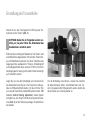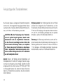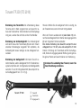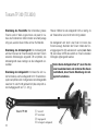
1
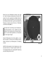
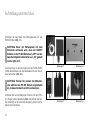
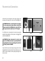
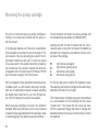
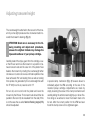
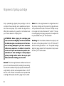
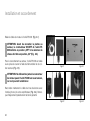
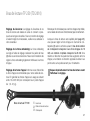
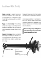
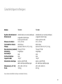
TD 2010
TD 2030
Bedienungsanleitung
User Manual
Mode d Emploi
www.thorens.com
TD 2010
TD 2030
Bedienungsanleitung
User Manual
Mode d Emploi
Inhalt
EINLEITUNG
6
SICHERHEITSHINWEISE
7
AUSPACKEN UND MONTAGE
8
AUFSTELLUNG UND ANSCHLUSS
10
INSTALLATION DES TONABNEHMERS
12
EINSTELLUNG DER TONARMHÖHE
13
FEINJUSTAGE DES TONABNEHMERS
14
TONARM TP 250 (TD 2010)
15
TONARM TP 300 (TD 2030)
16
BETRIEB DES PLATTENSPIELERS
17
WARTUNG UND PFLEGE
18
TECHNISCHE DATEN
19
SERVICEINFORMATIONEN
20
Table of Contents
Table des matiéres
INTRODUCTION
22
INTRODUCTION
38
HINTS FOR SAFETY AND PRECAUTION
23
CONSIGNES DE SECURITE
39
UNPACKING AND ASSEMBLY
24
DEBALLAGE ET MONTAGE
40
PLACEMENT AND CONNECTIONS
26
INSTALLATION ET RACCORDEMENT
42
MOUNTING THE PICKUP CARTRIDGE
28
INSTALLATION DE LA CELLULE DE LECTURE
44
ADJUSTING TONEARM HEIGHT
29
REGLAGE DE LA HAUTEUR DU BRAS
45
ALIGNMENT OF PICKUP CARTRIDGE
30
REGLAGE PRECIS DE LA CELLULE
46
TONEARM TP 250 (TD 2010)
31
BRAS DE LECTURE TP 250 (TD 2010)
47
TONEARM TP 300 (TD 2030)
32
BRAS DE LECTURE TP 300 (TD 2030)
48
OPERATION
33
UTILISATION DE LA PLATINE
49
MAINTENANCE AND CARE
34
MAINTENANCE ET ENTRETIEN
50
TECHNICAL SPECIFICATIONS
35
CARACTERISTIQUES TECHNIQUES
51
SERVICE INFORMATION
36
INFORMATIONS SERVICE APRES-VENTE
52
Einleitung
Herzlichen Glückwunsch zum Kauf Ihres
neuen TD 2010 / 2030.
Wir hoffen, dass Sie mit Ihrem neuen Plattenspieler viel
Freude haben werden. In Verbindung mit einem guten
Tonabnehmersystem besitzt dieses Laufwerk herausragende Wiedergabequalitäten. Fertigung und Montage
erfolgen komplett in Deutschland, so dass Sie sich auch
noch nach Jahren auf das Gerät verlassen können.
Bitte Denken Sie daran, dass dieser Plattenspieler ein Präzisionsinstrument ist, das stets mit Sorgfalt behandelt werden muss. Wir empfehlen Ihnen daher, diese Bedienungsanleitung vor der ersten Ingebrauchnahme aufmerksam
durchzulesen. Sie enthält wichtige Hinweise für Aufstellung, Anschluß und Konfiguration Ihres neuen Laufwerks.
Sollten Sie darüber hinaus noch Fragen haben, so können
Sie sich jederzeit an Ihren Thorens Fachhändler wenden.
6
Sicherheitshinweise
BITTE VOR DER ERSTMALIGEN INBETRIEBNAHME
AUFMERKSAM LESEN!
VORSICHT
Um einen elektrischen Schlag zu vermeiden, darf das Gehäuse des
Netzteils nicht geöffnet werden. Im Geräteinneren befinden sich keine
vom Benutzer zu wartenden Teile.
WARNUNG
UM DER GEFAHR VON FEUER UND EINES ELEKTRISCHEN SCHLAGES VORZUBEUGEN, DARF DAS GERÄT WEDER REGEN NOCH
FEUCHTIGKEIT AUSGESETZT WERDEN.
ERLÄUTERUNG DER GRAFISCHEN SYMBOLE
Das Blitz-Symbol mit dem nach unten weisenden
Pfeil im gleichseitigen Dreieck warnt vor “gefährlicher Spannung” im Gehäuseinneren, deren Höhe für
eine Gefährdung von Personen durch einen Stromschlag ausreichend ist.
Das Ausrufezeichen innerhalb des gleichseitigen
Dreiecks macht auf wichtige Bedienungs- und Wartungshinweise in der beiliegenden Bedienungsanleitung aufmerksam.
Dieses Elektronikprodukt entspricht den gültigen Richtlinien
zur Erlangung des CE-Zeichens. Alle notwendigen Prüfungen
wurden mit positivem Ergebnis vorgenommen.
WICHTIG: ENTSORGUNG VON ELEKTROGERÄTEN DURCH VERBRAUCHER IN PRIVATEN
HAUSHALTEN INNERHALB DER EU
Dieses Symbol auf dem Produkt oder dessen Verpackung gibt an, dass dieses Produkt nicht zusammen
mit dem Restmüll entsorgt werden darf. Es obliegt
daher Ihrer Verantwortung, das Gerät an einer entsprechenden Stelle für die Entsorgung oder Wiederverwertung von Elektrogeräten aller Art abzugeben
(z.B. ein Werkstoffhof). Die separate Sammlung und
das Recyceln Ihrer alten Elektrogeräte zum Zeitpunkt
ihrer Entsorgung trägt zum Schutz der Umwelt bei
und gewährleistet, dass sie auf eine Art und Weise
recycelt werden, die keine Gefährdung für die Gesundheit von Mensch und Umwelt darstellt. Weitere Informationen darüber, wo Sie alte Elektrogeräte
zum Recyceln abgeben können, erhalten Sie bei
den örtlichen Behörden, Werkstoffhöfen oder dort,
wo Sie das Gerät erworben haben.
7
Auspacken und Montage
Nehmen Sie das Gerät und die mitgelieferten Einzelteile
vorsichtig aus der Verpackung.
Lieferumfang:
1 x Bedienungsanleitung
1 x Chassis (mit/ohne Tonarm)
1 x Motor im Standgehäuse
1 x Thorens Antriebsriemen
1 x Plattenteller mit Filzmatte
1 x Tonarmgewicht
1 x Elektronikeinheit PS 800
1 x Netzteil
1 x Netzkabel
1 x Cinchkabel
1 x Adapter für 17 cm Schallplatten
3 x Fußunterlage
2 x Schutzhandschuh
ACHTUNG: Die Oberflächen von Chassis und
Plattenteller sind sehr kratzempfindlich. Verwenden Sie daher zur Montage unbedingt die beiliegenden Schutzhandschuhe.
8
Legen Sie zunächst die Unterlagen für die Spikespitzen an
den Platz, an dem das Laufwerk aufgestellt werden soll.
Die Unterlagen verhindern, dass empfindliche Oberflächen
durch die Spikes des Plattenspielers beschädigt werden.
Stellen Sie den Plattenspieler nun auf diese Unterlagen
und richten Sie ihn so aus, dass er waagrecht steht. Sie
können die Höhe der Füße anpassen, indem Sie deren
Spitzen drehen. Kontrollieren Sie die Höheneinstellung
danach mithilfe einer Wasserwaage und korrigieren Sie
gegebenfalls.
Nun muss der Motor in der dafür vorgesehenen Aussparung links hinten platziert werden. Heben Sie hierfür das
Chassis an und positionieren Sie den Motor unter der
Aussparung. Senken Sie nun das Chassis langsam ab, so
dass sich der Motor von unten in die Aussparung schiebt.
Gehen Sie hierbei sehr vorsichtig vor, um die Oberfläche
des Plattenspielers nicht zu verkratzen. Die Motoreinheit
sollte an ihrer endgültigen Position das Chassis nicht mehr
berühren.
Setzen Sie nun den Plattenteller vorsichtig in das Lager
ein. Achten Sie dabei unbedingt darauf, dass die Achsspitze nicht auf den Lagerboden aufschlägt! Drehen Sie
den Teller von Hand und prüfen Sie, ob er sich ohne großen Widerstand drehen lässt. Legen Sie anschließend die
Filzmatte auf. Spannen Sie den Riemen um Plattenteller
und Riemenscheibe (Abb. 1).
Vermeiden Sie Öl- oder Fettspuren auf Antriebsriemen,
Motor-Riemenscheibe und der Lauffläche des Plattentellers. Falls notwendig, können Sie diese Teile mit
einem in reinem Alkohol getränkten, nicht fasernden
Tuch oder Lappen reinigen.
Wurde Ihr Plattenspieler ohne Tonarm geliefert, so montieren Sie diesen nun bitte nach der Anleitung des Herstellers. Ansonsten ist der Plattenspieler nun vollständig
montiert.
Abbildung 1
WICHTIG: Bitte bewahren Sie die Verpackung auf, falls
das Gerät einmal zum Transport verpackt werden muss.
Für Transportschäden durch unsachgemäße Verpackung
wird keine Haftung übernommen!
9
Aufstellung und Anschluss
Verbinden Sie das Kabel des Motorgehäuses mit der
PS 800 Einheit (Abb. 2.1).
ACHTUNG: Bevor der Plattenspieler mit dem
Stromnetz verbunden wird, muss der ON/OFF
Schalter an der PS 800 Einheit auf „OFF“ und der
Geschwinidigkeitswahlschalter auf „33“ gestellt
werden (Abb. 2.2).
Zum Anschluss an das Stromnetz wird die PS 800 Einheit
mithilfe des Netzteils und des Netzkabels mit einer Steckdose verbunden (Abb. 2.3).
Abbildung 2.1
Abbildung 2.2
Abbildung 2.3
Abbildung 2.4
ACHTUNG: Trennen Sie niemals den Motorstecker während die PS 800 Einheit eingeschaltet
ist, da diese hierdurch zerstört werden kann.
Verbinden Sie nun das Kabel des Tonarms mit dem (Phono-) Eingang Ihres Verstärkers (Abb. 2.4). Achten Sie hierbei unbedingt auf eine korrekte Verpolung (linker-/rechter
Kanal!) der Anschlüsse.
10
Hinweis: Für Verstärker ohne Phonoeingang wird zusätzlich ein spezieller Phonovorverstärker benötigt. Für Verstärker mit einer 5-poligen Eingangsbuchse nach DIN wird
zusätzlich ein spezielles Adapterkabel benötigt. Bitte wenden Sie sich in diesen Fällen an Ihren Fachhändler.
Achten Sie bei der Aufstellung Ihres neuen Plattenspielers
darauf, einen Mindestabstand zu anderen elektronischen
Geräten (z.B. Verstärker, Reciever oder CD-Spieler) einzuhalten, da es sonst zu magnetischen Einstrahlungen
auf das Tonabnehmersystem kommen kann, welche sich
durch Brummstörungen in der Wiedergabe äußern.
Thorens Plattenspieler sind relativ unempfindlich gegenüber Erschütterungen. Dennoch stellen diese ein generelles
Problem bei der Plattenwiedergabe mit hochwertigen Tonabnehmern dar. Wählen Sie deshalb ein möglichst stabiles
Möbelstück zur Aufstellung und vermeiden Sie die Nähe
zu Lautsprechern.
Leider reicht dies in älteren Häusern mit Holzbalkendecken bisweilen nicht aus. In der Regel hilft hier allerdings
die Aufstellung des Plattenspielers auf einer Konsole, die
mit geeigneten Konsolenträgern an einer tragenden Zimmerwand befestigt wird.
Magnetische Störungen kann man leicht ermitteln und
beseitigen, indem man Aufstellung und Position der
Geräte zueinander verändert.
11
Installation des Tonabnehmers
Installieren und konfigurieren Sie Ihr Tonabnehmersystem
entsprechend der Montageanleitung des Herstellers und
nehmen Sie alle notwendigen Einstellungen vor.
An den Thorens Tonarmen können Tonabnehmersysteme
mit einem standardisierten Abstand der Befestigungslöcher von 12,5 mm (1/2 ”) montiert werden.
Im Folgenden erhalten Sie einige Hinweise zur Installation und Konfiguration von Thorens Tonarmen, die analog
auch für andere Fabrikate gelten können. Halten Sie sich
jedoch im Zweifel immer an die Anleitung des jeweiligen
Herstellers. Spezielle Konfigurationshinweise für die Thorens Tonarme TP 250 und TP 300 finden Sie ab Seite 15.
Die vier farblich gekennzeichneten Anschlußlitzen werden
auf die entsprechenden Anschluß-Stifte (identische Farbe)
des Tonabnehmersystems geschoben.
R
G
L
G
rechter Kanal, rot (Signal)
rechter Kanal, grün (Masse)
linker Kanal, weiß (Signal)
linker Kanal, blau (Masse)
Hinweis: Sollte Ihr Plattenspieler mit montiertem Tonarm
und Tonabnehmersystem geliefert worden sein, so sind
alle Einstellungen bereits werkseitig vorgenommen. Einzig die Auflagekraft muss noch eingestellt werden, da das
Tonarmgewicht für den Transport deinstalliert wurde.
Ziehen Sie die Montageschuhe zunächst nur lose ab. Die
Feinjustage des Tonabnehmers erfolgt nach dem Einstellen der Tonarmhöhe.
Montieren Sie den Tonabnehmer in die dafür vorgesehenen Bohrungen des Tonabnehmerkopfs. Belassen Sie
dabei den Nadelschutz – wenn möglich – auf dem Tonabnehmer, um Beschädigungen der Abtastnadel zu vermeiden.
Hinweis: Bei Grado Tonabnehmern sollten die mitgelieferten Schrauben von unten durch den Tonabnehmer
geführt werden und die Mutter oben auf das Headshell
geschraubt werden, da sie am Systemkörper nur schwer
zu verwenden sind.
12
Einstellung der Tonarmhöhe
Drehen Sie nun das Tonarmgewicht in Richtung der Tonarmbank auf den Tonarm (Abb. 3).
ACHTUNG: Gehen Sie im Folgenden extrem vorsichtig vor, da jeder Fehler die Abtastnadel des
Tonabnehmers zerstören kann!
Entfernen Sie vorsichtig den Nadelschutz. Der Tonarm wird
anschließend bei abgesenktem Lift zwischen Tonarmstütze und Plattenteller positioniert und durch Verdrehen des
Gegengewichtes ausbalanciert. Hinweis: Antiskatingkraft
und Auflagekraft (falls diese, wie beim TP 300, nicht durch
das Gegengewicht erzeugt wird) sollten hierbei unbedingt
auf 0 redurziert werden.
Legen Sie nun eine alte Schallplatte auf und senken Sie
die Abtastnadel vorsichtig ab. Das Tonarmrohr sollte parallel zur Plattenoberfläche stehen. Ist dies nicht der Fall,
so muss die Tonarmhöhe mittels VTA justiert werden. VTA
bedeutet Vertical Tracking Adjustment, dieses System
ermöglicht es, den Tonarm mithilfe eines Spannmechanismus (Abb. 3) auf die Höhe des jeweiligen Tonabnehmers
einzustellen.
Abbildung 3
Um die Einstellung vorzunehmen, müssen Sie zunächst
die Spannschraube öffnen. Anschließend kann der Tonarm in die gewünschte Höhe gebracht werden. Ziehen Sie
die Schraube nun vorsichtig wieder an.
13
Feinjustage des Tonabnehmers
Nur bei einer genauen Justage des Tonabnehmersystems
kommen die hervorragenden Klangeigenschaften dieses
Laufwerks voll zur Geltung. Sollte Sie hierbei Probleme haben, so hilft Ihnen Ihr Fachhändler gerne dabei.
ACHTUNG: Bei der Feinjustage des Tonabnehmers ist größte Sorgfalt geboten, damit weder
Abtastnadel noch die empfindliche Feinmachanik des Tonarms beschädigt werden. Sollten Sie
hierin keinerlei Erfahrung haben, so empfehlen
wir Ihnen, dies einem Fachmann zu überlassen.
Falsch eingestellte Tonabnehmersysteme können zu starkem Klangverlust bis hin zu Schäden
an der Schallplatte führen!
Azimut: Dies ist der Winkel zwischen Nadelträger und
Schallplattenrille. Er sollte 90° betragen (hiervon ausgenommen sind Systeme, deren Nadel absichtlich schief
eingebaut ist). Der Azimut kann am TP 250 und TP 300
nicht eingestellt werden. Sie sollten mit diesen Tonarmen
daher nur Tonabnehmer verwenden, die einen korrekten
Azimut besitzen.
14
Kröpfungswinkel: Der Kröpfungswinkel ist der Winkel
zwischen der Längsachse des Tonabnehmers und der
Tonarmachse. Bei allen Drehpunktarmen (wie die Tonarme
TP 250 und TP 300) liegen die optimalen Werte zwischen
21° und 24°. Zur Einstellung benötigen Sie eine spezielle
Schablone, welche im Fachhandel erhältlich ist.
Überhang: Der Überhang ist die Strecke, welche die Tonabnehmernadel über die Plattentellermitte hinausragt. Der
Überhang sollte bei den Tonarmen TP 250 und TP 300 ca.
17 mm betragen. Zur Einstellung benötigen Sie eine spezielle Schablone, welche im Fachhandel erhältlich ist.
Tonarm TP 250 (TD 2010)
Einstellung des Tonarmlifts: Die Lifteinstellung dieses
Tonarms wird im Werk vorgenommen und passt für nahezu alle Tonabnehmer. Sollte trotzdem eine Nachjustage
nötig sein, wenden Sie sich bitte an Ihren Fachhändler.
Einstellung der Antiskatingkraft: Die Antiskatingkraft
wird durch den auf der Tonarmbank (2) unter dem Tonarm
sitzenden Schieberegler eingestellt. Wir empfehlen, die
Antiskatingkraft etwas niedriger als die Auflagekraft einzustellen.
Einstellung der Auflagekraft: Informieren Sie sich zunächst darüber, welche Auflagekraft für Ihr Tonabnehmersystem empfohlen wird. Im Allgemeinen sind Auflagekräfte
zwischen 10 und 25 mN gebräuchlich (dies entspricht einem Auflagegewicht von 1,0 - 2,5 g).
Tonarm TP 250
➀
➁
➂
Tonarmlift
Tonarmbank
Gegengewicht
Hinweis: Wählen Sie die Auflagekraft nicht zu niedrig, da
der Tonabnehmer sonst nicht mehr richtig arbeitet.
Wenn der Tonarm ausbalanciert ist (siehe Seite 13), können Sie die Auflagekraft durch Drehen des Gegengewichts
(3) nach folgendem Schema einstellen:
Eine halbe Umdrehung des Gewichts entspricht einer
Auflagekraft von 10 mN, eine volle entspricht 20 mN.
Drehen in Richtung der Tonarmbank erhöht die Auflagekraft, Drehen in entgegengesetzter Richtung verringert sie.
Die grünen Punkte am Gewicht dienen zur Orientierung.
Arretieren Sie unbedingt den Tonarm, bevor Sie
diese Einstellung vornehmen.
➁
➂
➀
15
Tonarm TP 300 (TD 2030)
Einstellung des Tonarmlifts: Die Lifteinstellung dieses
Tonarms wird im Werk vorgenommen und passt für nahezu alle Tonabnehmer. Sollte trotzdem eine Nachjustage
nötig sein, wenden Sie sich bitte an Ihren Fachhändler.
Einstellung der Antiskatingkraft: Die Antiskatingkraft
wird durch den auf der Tonarmbank (2) unter dem Tonarm
sitzenden Schieberegler eingestellt. Wir empfehlen, die
Antiskatingkraft etwas niedriger als die Auflagekraft einzustellen.
Hinweis: Wählen Sie die Auflagekraft nicht zu niedrig, da
der Tonabnehmer sonst nicht mehr richtig arbeitet.
Die Auflagekraft wird durch eine Feder im Inneren des
Tonarms erzeugt. Nachdem der Tonarm mittels des Tonarmgegengewichts (3) ausbalanciert wurde (siehe Seite
13), kann diese mit Hilfe des seitlich am Tonarm sitzenden
Drehreglers (4) eingestellt werden.
Einstellung der Auflagekraft: Informieren Sie sich zunächst darüber, welche Auflagekraft für Ihr Tonabnehmersystem empfohlen wird. Im Allgemeinen sind Auflagekräfte
zwischen 10 und 25 mN gebräuchlich (dies entspricht einem Auflagegewicht von 1,0 - 2,5 g).
Tonarm TP 300
16
➀
➁
➂
➃
Tonarmlift
Tonarmbank
Gegengewicht
Drehregler für Auflagekraft
Stellen Sie die Auflagekraft auf „0“, bevor Sie den
Tonarm ausbalancieren und arretieren Sie diesen
anschließend, bevor Sie die Einstellung der Auflagekraft vornehmen.
➁
➃
➀
➂
Betrieb des Plattenspielers
Der Motor des Plattenspielers wird über die angeschlossene PS 800 Einheit (Abb. 6) gesteuert. Der rechte Schalter
dient zur Geschwindigkeitsauswahl. Folgende Geschwindigkeiten stehen zur Verfügung: 33 ⅓ U/min für Langspielplatten und 45 U/min für kleine Schallplatten. Links daneben befindet sich der ON/OFF Schalter mit dem der
Motor an- bzw. ausgeschaltet wird.
Zum Abspielen einer Platte wird der Plattenspieler zunächst
mit der entsprechenden Geschwindigkeit gestartet. Dann
wird der Tonarmlift angehoben, hierzu muss der Hebel
nach hinten oben bewegt werden. Nun wird der Tonabnehmer über der Einlaufrille oder über dem gewünschten
Stück positioniert und anschließend mithilfe des Lifts auf
die Platte abgesenkt (Hebel nach vorne unten bewegen).
Abbildung 6
Der Plattenspieler besitzt keine automatische Endabschaltung. Sobald die Auslaufrille erreicht ist, muss der Tonarm
mittels Handlift von der Platte gehoben und der ON/OFF
Schalter betätigt werden.
17
Wartung und Pflege
Ihr Plattenspieler benötigt keinerlei ständige Wartung.
Staub, der sich im Laufe der Zeit auf dem Chassis absetzt,
kann mit einem weichen und feuchten Tuch entfernt werden. Hinweis: Verwenden Sie zur Reinigung am besten ein
feuchtes Brillenputztuch.
ACHTUNG: Verwenden Sie zur Reinigung auf keinen Fall ein Papiertuch oder sonstige raufasrige
Materialien, da diese die empfindliche Acryloberfläche verkratzen können. Ein trockenes Tuch
hingegen kann unerwünschte elektrostatische
Aufladungen verursachen.
Den Thorens Präzisionsriemen sollten Sie alle 2 Jahre ersetzen. Sollte das Gerät über längere Zeit nicht in Betrieb
sein, so empfiehlt es sich, den Riemen abzunehmen, um
einer vorzeitigen Alterung vorzubeugen.
Bei häufigem Gebrauch sollten Sie alle 5 Jahre eine
Überprüfung des Lagers vornehmen lassen und dessen
Schmierung erneuern.
18
Technische Daten
Modell
TD 2010
TD 2030
Antriebssystem
Antrieb
Riemenantrieb (außenliegend)
elektronisch geregelter
AC-Synchronmotor
33 ⅓, 45 U/min
elektronisch
Aluminium 300 mm (12”), 4,5 kg
Thorens TP 250
magnetisch
keine
keine
140 pF
PS 800 Elektronikeinheit,
landesspezifisches Netzteil
420 x 340 x 160 mm (B x T x H)
18,0 kg
Riemenantrieb (außenliegend)
elektronisch geregelter
AC-Synchronmotor
33 ⅓, 45 U/min
elektronisch
Aluminium 300 mm (12”), 6,2 kg
Thorens TP 300
magnetisch
keine
keine
140 pF
PS 800 Elektronikeinheit,
landesspezifisches Netzteil
420 x 340 x 200 mm (B x T x H)
22,0 kg
Geschwindigkeiten
Geschw.umschaltung
Plattenteller
Tonarm (standard)
Antiskating
Automatik
Endabschaltung
Kabelkapazität
Stromversorgung
Abmessungen
Gewicht
Technische Änderungen vorbehalten. Handmade in Germany.
19
Serviceinformationen
Ihr Fachhändler oder Vertrieb sind jederzeit kompetente
Ansprechpartner, die Ihnen bei sämtlichen Fragen rund
um Ihr Thorens Produkt gerne zur Verfügung stehen.
Sie können Thorens auch direkt kontaktieren:
Thorens Export Company AG
Im Huebel 1, CH-4304 Giebenach, Schweiz
www.thorens.com, [email protected]
Bitte kontaktieren Sie im Garantiefall immer zuerst Ihren
Fachhändler oder Vertrieb!
Weitere Informationen unter:
www.thorens.com/de
20
Notizen
21
Introduction
Congratulations for your purchase of the
new TD 2010 / 2030.
We hope that your new record player will give you lots
of listening pleasure. In combination with a good pickup
cartridge this turntable is to yield outstanding sound. Manufacturing and assembly of this record player has been
carried out in Germany which will guarantee you its high
quality and functionality being maintained for many years
to come.
Please keep in mind that this device is a precision instrument and therefore requires some attention and care. We
strongly advise to read these instructions attentively before proceeding with the set-up as it contains all necessary information and guidance for assembly, placement,
set-up and configuration of your new record player.
In the event that you have any question this user manual
cannot answer please do not hesitate to ask your Thorens
dealer for further assistance.
22
Safety instructions
PLEASE READ THIS PAGE CAREFULLY BEFORE
OPERATING YOUR UNIT!
CAUTION
To reduce risk of electric shock, do not remove the cover (or back).
No user-serviceable parts inside.
WARNING
TO PREVENT FIRE OR SHOCK HAZARD, DO NOT EXPOSE THIS
APPLIANCE TO RAIN OR MOISTURE.
EXPLANATION OF GRAPHICAL SYMBOLS
The lightning flash with arrowhead symbol, within
an equilateral triangle, is intended to alert you to
the presence of uninsulated ‘dangerous voltage’
within the product’s enclosure that may be of sufficient magnitude to constitute an electric shock to
persons.
The exclamation point within an equilateral triangle
is intended to alert you to the presence of important
operating and maintenance (servicing) instructions in
the literature accompanying the appliance.
This product was tested and complies with all the
requirements for the CE Mark.
IMPORTANT: DISPOSAL OF WASTE EQUIPMENT BY USERS IN PRIVATE HOUSEHOLDS
IN THE EUROPEAN UNION
This symbol on the product or on its packaging indicates that this product must not be disposed off
with your other household waste. Instead, it is your
responsibility to dispose of your waste equipment by
handing it over to a designated collection point for
the recycling of waste electrical and electronic equipment. The separate collection and recycling of your
waste equipment at the time of disposal will help to
conserve natural resources and ensure that it is recycled in a manner that protects human health and
the environment. For more information about where
you can drop off your waste equipment for recycling,
please contact your local city office, your household
waste disposal service or the shop where you purchased the product.
23
Unpacking and Assembly
Carefully remove the unit and its accessories from the
shipping box.
Supplied items:
1 x user manual
1 x plinth (with/without tonearm)
1 x motor in housing
1 x Thorens drive belt
1 x platter with felt mat
1 x tonearm counterweight
1 x electronic control unit PS 800
1 x mains adaptor
1 x power cord
1 x set of RCA interconnecting leads
1 x adaptor for single records
3 x protective disks
2 x cotton glove
ATTENTION: The surface of both plinth and platter is quite sensitive to scratches. It is therefore
recommended to wear the supplied gloves whilst
the record player is being assembled.
24
Proceed with placing the three protective disks where the
record player is eventually going to stay. They are provided to prevent the sensitive surface of furniture from being
damaged by the record player’s spiked feet.
Now put the record player respectively its feet onto the
disks and after the final position has been achieved make
sure that the plinth is fairly level. For any fine-adjustments
turn the tip of each foot up or down until the plinth is in
a perfect horizontal position. This procedure is best controlled (and corrected if necessary) with the help of good
spirit level.
The motor housing is now to be inserted into the dedicated recess at the rear left corner. This is carried out by
having the plinth lifted up and the motor positioned exactly
beneath the recess. Slowly lower the plinth so that the
motor housing is entering the recess. Great care should
be taken while doing this in order to prevent any scratches
on the plinth surface. Being in its final position the motor
housing should not be touching the inside of the recess.
Now take the platter with both hands and hold its axle
perpendicular over the hole in the bearing. Slowly and very
carefully insert the axle into the bearing while making sure
that it must not forcefully hit the bottom of the bearing.
After the platter has been put in place turn it manually to
see if it runs smoothly and with ease. Add felt mat and
finally loop the belt around the outer rim of the platter and
the motor pulley (Fig. 1).
Avoid any oil or greasy substance to get onto the belt
and the transmission area of platter and motor pulley.
If necessary you may clean them with a lint-free tissue
soaked in an alcoholic dilution (e.g. ethanol).
Unless you have acquired your record player with tonearm, you can now proceed with mounting a foreign tone
arm according to the instructions supplied by its manufacturer. Otherwise your record player is now completely
assembled.
IMPORTANT: It is highly recommended to save the shipping box and all packing material in case the record player
needs to be packed again for transportation.
Fig. 1
Thorens cannot be held responsible for any damage that
may occur during transport on the ground that the record
player has not been properly packed.
25
Placement and Connections
Connect the cord coming from the motor housing to the
rear panel of the electronic control unit PS 800 (Fig. 2.1).
ATTENTION: Before connecting the record player
to the mains power please make sure that the
power switch on the PS 800 unit is set to OFF and
the speed selector switch set to “33” (Fig.2.2).
The PS 800 unit is connected to the mains by using the
supplied mains adaptor and the power cord plugged into
a wall socket (Fig. 2.3).
Fig. 2.1
Fig. 2.2
Fig. 2.3
Fig. 2.4
ATTENTION: Never disconnect the motor plug
from the PS 800 unit while it is switched ON. Disregarding this advise may damage the electronic
circuitry inside the PS 800.
Take the RCA interconnect leads and plug them into the
designated (phono) input jacks at the rear side of your amplifier or receiver. Make sure that polarity (left/right channel!) is correct.
26
Hint: if your amplifier lacks a built-in phono stage you need
to acquire a special external phono-preamplifier. For amplifiers/receivers featuring a 5-pin DIN-socket at the phono
input section you will need a special adaptor (RCA to DIN)
which may be available from your Thorens dealer.
When placing the record player to its final position make
sure that it is a fair distance away from other audio devices, such as amplifier, receiver or CD player. This measure
is to avoid electro-magnetic interferences which can yield
a distorting effect in the sensitive pickup cartridge, which
may be audible as hum during playback.
Electro-magnetic interferences however can be disclosed and eliminated by simply changing the position
of the record player with respect to the other devices.
Thorens record players are relatively insensitive when subject to foot-fall shocks or airborne resonance. Nevertheless, a general problem remains when it comes to playing
back vinyl records with a high-quality pickup cartridge. It
is therefore highly recommended to choose a sturdy piece
of furniture for placement and to avoid the proximity of the
record player to the loudspeakers.
Under certain circumstances all these precautions may not
be good enough in older houses with wooden floor construction. Here, in most cases a solid shelf firmly mounted
to a supporting wall can be very beneficial for the sonic
properties of the record player if it is placed on such a shelf
or console.
27
Mounting the pickup cartridge
You can now mount and adjust your pickup cartridge according to the instructions provided with the pickup or
with the tonearm.
In the following chapters you’ll find some comprehensive
hints and advise concerning the correct mounting of Thorens tonearms. They may accordingly be used for mounting foreign tonearms as well, yet if in doubt you should
in any case resort to the original instructions provided by
the manufacturer of the tonearm. Special hints about the
configuration of the Thorens tonearms TP 250 and TP 300
are to be found on page 31-32 of this manual.
Hint: If you happen to have acquired this record player as a
complete system, i.e. with tonearm and pickup cartridge,
there are no adjustments necessary because everything
has already been carried out for you in the Thorens factory. Only the tracking force needs to be adjusted.
Mount the pickup cartridge to the slots in the tonearm’s
headshell. While doing this basic work it is recommended
to leave the stylus guard attached to the cartridge in order
to avoid damaging of the delicate stylus and cantilever.
28
Thorens tonearms will accept any pickup cartridge with
the standard fixing hole distance of 12.5 mm (1/2 ”).
Carefully and with the help of tweezers the four colourcoded litz wires coming from the tonearm’s headshell are
attached to the respective pins (identical colours) at the
rear face of the cartridge.
R
G
L
G
right channel, red (signal)
right channel, green (ground)
left channel, white (signal)
left channel, blue (ground)
For the time being do not tighten the headshell screws.
Fine-adjusting and fixing the cartridge is done after having
determined the final tone arm height.
Hint: If Grado pickup cartridges are going to be employed
it is recommended to fix the cartridge with the screws
“upside down”. This means that the screws are inserted from underneath through the holes of cartridge and
headshell whereby the nuts are to fix the screws on top of
the headshell.
Adjusting tonearm height
The counterweight is attached to the rear end of the tonearm by some slight pressure and a clockwise rotation towards the tonearm’s bearings (Fig. 3).
ATTENTION: Great care is necessary for the following mounting and adjust-ment procedures,
because the slightest mistake may damage the
stylus and cantilever of your pickup cartridge.
Carefully detach the stylus guard from the cartridge. Lower the lift lever and move the tonearm to a position in between tonearm rest and the outer rim of the platter. Now
balance the tonearm by rotating the counterweight either
clockwise or counter-clock-wise until total equilibrium has
been achieved. Hint: anti-skating force as well as tracking
force (unless it is generated by the counterweight like with
the TP 250) must in any case be set to “0”.
Put an old, worn record onto the platter and lower the
tonearm by the lift lever. The tonearm tube should then be
parallel to the record (to be visualised from the side). If this
is not the case the so-called Vertical Tracking Angle (VTA)
should be adjusted.
Fig. 3
A special clamp mechanism (Fig. 3) however allows to
individually adjust the VTA according to the size of the
mounted pickup cartridge. Adjustments are made by
simply loosening the screw of the clamp mechanism and
carefully sliding the entire tonearm slightly up or down. Before doing so we advise to move the tonearm back onto
its rest. After the correct position for the VTA has been
found the clamp screw is to be tightened again.
29
Alignment of pickup cartridge
Only a painstakingly aligned pickup cartridge is able to
compliment the outstanding sonic capabilities and potential of this record player. If you consider the alignment too
difficult to be carried out by yourself, do not hesitate to ask
your Thorens dealer for a helping hand.
ATTENTION: When aligning the cartridge great
care is once more obligatory in order to avoid that
the delicate stylus or sensitive parts of the tonearm are being damaged. If you are a newcomer
without any experience it is better to leave this
work to an expert who knows the specific characteristics of most cartridges. A badly aligned
pickup cartridge will be well on the way to yield
bad sound and to damage your records!
Azimuth: This is the angle between cantilever and record
groove. It should be exactly 90° (excluding those cartridges in which the cantilever has purposely been installed with
a slight offset). Azimuth can be adjusted neither on the TP
250 nor on the TP 300. It is therefore most important that
a cartridge with precise azimuth is going to be mounted.
30
Offset: this is the angle between the longitudinal axis of
the pickup cartridge and the tonearm’s longitudinal axis.
In all pivoted tonearms (like TP 250 and TP 300) the optimum angle is to be found between 21° and 24°. The special cartridge alignment gauge required for this adjustment
may be available from your Thorens dealer.
Overhang: this is the distance between the stylus tip and
the centre of the platter spindle. For the TP 250 and TP
300 the overhang should be 17 mm. The special cartridge
alignment gauge required for this adjustment may be available from your Thorens dealer.
Tonearm TP 250 (TD 2010)
Adjusting the tonearm lift: It has already been adjusted
in the factory and can be considered suitable for nearly all
pickup cartridges in the market. However in the unlikely
case that the tonearm lift needs to be re-adjusted to fit a
special cartridge please contact your Thorens dealer.
Anti-skating force (bias): This is adjusted by shifting the
button on the tonearm’s lift bench (2). It is recommended
to set the anti-skating force slight below the value of the
tracking force.
Adjustment of tracking force: Make sure to inquire the
recommended tracking force for your pickup cartridge
from either the cartridge manufacturer or by consulting the
mounting instructions supplied with the cartridge. Tracking force is usually adjusted between 10 and 25 mN (corresponding to 1.0 and 2.5 grams).
Tonearm TP 250
➀
➁
➂
tonearm lift lever
tonearm bench
counterweight
Hint: Do not set too low a tracking force, because this may
prevent the pickup car-tridge from tracking properly.
After the tonearm has been correctly balanced (see page
29) you can apply the tracking force by rotating the counterweight (3) according to the following scheme: a half turn
of the counterweight corresponds to a tracking force of
10 mN (1.0 g) whereby a full turn corresponds to a force
of 20 mN (2.0 g). Turning the counter-weight towards the
bearings will increase tracking force, whereas turning the
weight into the opposite direction will decrease it.
Make sure that the tonearm is kept in its armrest
before doing these adjustments.
➁
➂
➀
31
Tonearm TP 300 (TD 2030)
Adjusting the tonearm lift: It has already been adjusted
in the factory and can be considered suitable for nearly all
pickup cartridges in the market. However in the unlikely
case that the tonearm lift needs to be re-adjusted to fit a
special cartridge please contact your Thorens dealer.
Anti-skating force (bias): This is adjusted by shifting the
button on the tonearm’s lift bench (2). It is recommended
to set the anti-skating force slight below the value of the
tracking force.
Adjustment of tracking force: Make sure to inquire the
recommended tracking force for your pickup cartridge
from either the cartridge manufacturer or by consulting the
mounting instructions supplied with the cartridge. Tracking force is usually adjusted between 10 and 25 mN (corresponding to 1.0 and 2.5 grams).
Tonearm TP 300
32
➀
➁
➂
➃
tonearm lift lever
tonearm bench
counterweight
anti-skating dial knob
Hint: Do not set too low a tracking force, because this may
prevent the pickup cartridge from tracking properly.
Tracking force is applied by a spring inside the bearing
assembly. After the tonearm has been correctly balanced
(see page 29) you can adjust the tracking force by turning
the dial knob (4) at the bearing assembly.
Set tracking force dial to “0” before balancing the
tonearm and make sure the tonearm is kept in
its armrest before proceeding with these adjustments.
➁
➃
➀
➂
Operation
The motor of the record player is electronically controlled
by the connected PS 800 unit (Fig. 6). The toggle switch
on the right is for selecting the speed whereby two speeds
are available: 33 ⅓ rpm for long playing records and 45
rpm for singles. The toggle switch on the left labelled ON/
OFF is to start or stop the motor.
For playing a record the turntable is first started with the
desired speed. Then lift the tonearm by slowly pushing
the lift lever up and back. Release the tonearm from its
rest and position it above the lead-in groove or above the
desired piece/track to be played. Slowly bring the lift lever
to the down-position whereupon the tonearm is smoothly
descending.
Fig. 6
This record player does not feature any automatic end-ofrecord shut-off facility. Therefore, as soon as the stylus has
reached the lead-out groove, the tonearm is to be lifted up
manually by the lever and the motor switched off.
33
Maintenance and Care
Your record player requires no particular maintenance.
If over the time dust has collected on the plinth you can
wipe it off with a moistened cloth. Hint: A pre-moistened
cleaning tissue for glasses is a very good choice for doing
this.
ATTENTION: Do not use paper tissue or any
coarse-fibred cloth because they may leave
scratches on the rather sensitive acryl surface.
Also refrain from using a dry cloth for cleaning
because this will in any case generate undesired
static charges.
The Thorens precision belt should be exchanged at least
every other year. If the record player is not in use for a
longer time, it is advisable to remove the belt in order to
prevent a premature ageing under tension.
If the record player is frequently in use it is recommended
to have the bearing checked and lubrication renewed after
about 5 years.
34
Technical Specifications
Model
TD 2010
TD 2030
Drive system
Motor
belt drive (via platter rim)
electronically controlled
AC synchronous motor
33 ⅓ and 45 rpm
electronically
aluminium 300 mm (12”) 4.5 kg
Thorens TP 250
magnetic
n/a
n/a
140 pF
PS 800 electronic control unit
country-specified mains adaptor
420 x 340 x 160 mm
18.0 kg
belt drive (via platter rim)
electronically controlled
AC synchronous motor
33 ⅓ and 45 rpm
electronically
aluminium 300 mm (12”) 6.2 kg
Thorens TP 300
magnetic
n/a
n/a
140 pF
PS 800 electronic control unit
country-specified mains adaptor
420 x 340 x 200 mm
22.0 kg
Speed
Speed change
Platter
Tonearm (standard)
Anti-skating
Automatic functions
Automatic shut-off
Capacity of leads
Voltage/Power supply
Dimensions (WxDxH)
Weight
Technical modifications subject to change. Handmade in Germany
35
Service Information
Your Thorens dealer or distribution partner shall be pleased
to assist you in the event that you have any further queries
or need additional information concerning Thorens products.
You may contact Thorens also directly:
Thorens Export Company Ltd.
Im Huebel 1, CH-4304 Giebenach, Switzerland
www.thorens.com, [email protected]
In case of warranty claims you are kindly requested to
first contact your Thorens dealer or distributor.
Further information may also be obtained from:
www.thorens.com
36
Notes
37
Introduction
Félicitations pour l’achat de votre nouvelle
platine TD 2010 / 2030.
Nous espérons que vous aurez beaucoup de plaisir avec
l’utilisation de votre nouvelle platine. Equipée d’une cellule de lecture de bonne qualité, cette platine vous offrira
une excellente qualité de reproduction. La fabrication et
le montage sont entièrement effectués en Allemagne, ce
qui vous garantit un usage satisfaisant pour de longues
années.
Veuillez lire avec attention la totalité de ce mode d’emploi
avant la première mise en service. Il contient d’importants
conseils pour l’installation, le raccordement et la configuration de votre nouvelle platine. N’oubliez jamais que cette
platine est un instrument de précision, qui doit toujours
être manipulé avec précaution.
Si vous aviez des questions dont les réponses ne se trouveraient pas dans ce mode d’emploi, veuillez vous adresser à votre revendeur.
38
Consignes de sécurité
A LIRE ATTENTIVEMENT AVANT LA PREMIERE
MISE EN SERVICE!
ATTENTION
Pour éviter tout choc électrique, le boîtier de l’alimentation ne doit pas
être ouvert. A l’intérieur de l’appareil ne se trouve aucune pièce nécessitant un entretien de la part de l’utilisateur.
AVERTISSEMENT
POUR EVITER TOUT DANGER D‘INCENDIE ET DE CHOC ELECTRIQUE, L‘APPAREIL NE DOIT PAS ETRE EXPOSE A LA PLUIE ET A L‘HUMIDITE.
EXPLICATION DES SYMBOLES GRAPHIQUE
Le symbole éclair avec flèche vers le bas dans le
triangle avertit d‘une „tension dangereuse“ à l‘intérieur de l‘appareil, dont le niveau est suffisant pour
présenter un danger de choc électrique aux personnes.
Le point d‘exclamation à l‘intérieur du triangle indique des instructions de commande et d‘entretien
figurant dans le présent mode d‘emploi.
Ce produit électronique est conforme aux directives européennes pour l‘obtention de la marque CE. Tous les essais
nécessaires ont été effectués avec un résultat positif.
IMPORTANT:
ELIMINATION
D‘APPAREILS
ELECTRIQUES PAR LES UTILISATEURS PARTICULIERS RESIDANT DANS LA CE
Ce symbole, figurant sur le produit ou sur son emballage, indique que ce produit ne doit pas être éliminé avec les ordures ménagères. Il est de votre responsabilité de remettre ce produit à une entreprise
d‘élimination ou de recyclage d‘appareils électriques
de tous types (par ex. une décharge spécialisée)
La collecte sélective et la réutilisation de tous vos
anciens appareils électroniques à l‘occasion de leur
élimination, contribuent à la protection de l‘environnement et assure qu‘il soient recyclés de manière à
éviter de porter atteinte à la santé humaine et à la
protection de la nature. Pour obtenir de plus amples informations sur les dépôts et le recyclage des
appareils électroniques usagés, adressez-vous aux
autorités locales, aux déchèteries ou au distributeur
qui vous a vendu l‘appareil.
39
Déballage et montage
Sortez l‘appareil et les pièces livrées de l‘emballage avec
précaution.
Contenu:
1 x Mode d‘emploi
1 x Châssis (avec/sans bras de lecture)
1 x Moteur dans le boîtier
1 x Courroie d‘entraînement Thorens
1 x Plateau avec feutre
1 x Poids du bras de lecture
1 x Unité électronique PS 800
1 x Alimentation
1 x Cordon secteur
1 x Câble Cinch
1 x Adaptateur pour disques 17 cm
3 x Embase de pied
2 x Gants de protection
ATTENTION: Les surfaces du châssis et du plateau sont sensibles aux rayures. Utilisez impérativement les gants de protection fournis pour le
montage.
40
Positionnez d‘abord les embases de pointes à l‘endroit
où vous voulez installer le lecteur. Les embases servent à
protéger les surfaces fragiles qui pourraient être endommagées par les pointes.
Placez maintenant la platine sur ces embases et réglez
son horizontalité. Vous pouvez régler la hauteur des pieds
en faisant tourner les pointes. Contrôlez ensuite le réglage
de la hauteur à l‘aide d‘un niveau à bulle et corrigez-le si
nécessaire.
Placez maintenant le moteur dans le logement prévu à
cet effet, à l‘arrière gauche. Soulevez le châssis et placez le moteur sous son logement. Abaissez maintenant
lentement le châssis afin que le moteur s‘insère dans son
logement par le dessous. Procédez avec beaucoup de
précaution afin de ne pas rayer la surface de la platine.
L‘unité moteur ne doit pas toucher le châssis dans sa position finale.
Placez maintenant prudemment le plateau dans son palier. Il faut absolument veiller à ce que la pointe de l‘axe ne
cogne pas dans le fond du palier! Faites tourner le plateau
à la main et vérifiez s‘il tourne sans offrir trop de résistance. Mettez ensuite le feutre en place. Tendez la courroie
autour du plateau et sur la poulie (Fig. 1).
Evitez toute trace d‘huile ou de graisse sur la courroie d‘entraînement, la poulie du moteur et la surface
d‘entraînement du plateau. Si nécessaire vous pouvez
nettoyer ces pièces à l‘aide d‘un tissu ou chiffon non
pelucheux, imprégné d‘alcool pur.
Si votre platine a été livrée sans bras de lecture, montez
celui-ci conformément aux instructions du fabricant. Dans
le cas contraire, la platine est maintenant entièrement
montée.
IMPORTANT: Veuillez conserver l‘emballage, au cas où
l‘appareil devrait être remballé pour le transport. Aucune
garantie de dommages de transport ne peut être acceptée
pour un appareil dont l‘emballage n‘est pas conforme!
Fig. 1
41
Installation et raccordement
Reliez le câble du moteur à l‘unité PS 800 (Fig. 2.1).
ATTENTION: Avant de raccorder la platine au
secteur, le commutateur ON/OFF de l‘unité PS
800 doit être en position „OFF“ et le sélecteur de
vitesse doit être en position „33“ (Fig. 2.2).
Pour le raccordement au secteur, l‘unité PS 800 est reliée
à une prise de courant à l‘aide de l‘alimentation et du cordon secteur. (Fig. 2.3).
Fig. 2.1
Fig. 2.2
Fig. 2.3
Fig. 2.4
ATTENTION: Ne débranchez jamais le connecteur
du moteur quand l‘unité PS 800 est sous tension,
car ceci pourrait la détériorer.
Raccordez maintenant le câble du bras de lecture avec
l‘entrée (phono) de votre amplificateur (Fig. 2.4). Remarque: Respectez impérativement la bonne polarité
42
Remarque: Si l‘amplificateur n‘a pas d‘entrée phono, il est
nécessaire d‘utiliser en plus un préamplificateur phono
spécial. Pour les amplificateurs ayant une prise d‘entrée
à 5 pôles selon DIN, procurez-vous un câble d’adaptation
chez votre revendeur.
Les platines Thorens sont relativement insensibles aux vibrations. Cependant, celles-ci posent en général un problème pour la reproduction des disques avec des lecteurs
de haute qualité. Choisissez un meuble stable comme
support et évitez la proximité des haut-parleurs.
Lors de l‘installation de votre nouvelle platine, veillez à
respecter une distance minimale par rapport aux autres
appareils électroniques (par ex. amplificateur, récepteur
ou lecteur de CD), car des rayonnements électromagnétiques pourraient perturber le système de lecture, ce qui
se traduirait par des bourdonnements en cours de reproduction.
Mais ceci n‘est pas suffisant dans le cas d‘anciennes demeures avec poutraison de plancher en bois. En général,
dans ce cas, il faut toujours placer la platine sur une console, qui est elle-même vissée au mur porteur de la pièce
à l‘aide de ses propres supports de console.
On peut facilement identifier et éliminer les perturbations magnétiques en modifiant la disposition de la platine par rapport aux autres appareils.
43
Installation de la cellule de lecture
Installez et configurez votre système de lecture conformément aux instructions de montage du fabricant et effectuez tous les réglages nécessaires.
Sur les bras de lecture Thorens, il est possible de monter
des systèmes de lecture ayant un écart standard entre les
trous de fixation de 12,5 mm (1/2 ”).
Ci-dessous, vous trouverez quelques instructions pour
l‘installation et la configuration de bras de lecture de Thorens, qui peuvent également être valables pour d‘autres
fabrications. En cas de doute, reportez-vous toujours aux
instructions de chacun des fabricants. Vous trouverez des
instructions spéciales de configuration pour les bras de
lecture Thorens TP 250 et TP 300 à partir de la page 44.
Les quatre cosses de raccordement repérées par couleurs doivent être connectées aux picots correspondants
(même couleur) du système de lecture.
Remarque: Si votre platine vous a été livrée avec le bras
et le système de lecture montés, tous les réglages ont
été effectués en usine. Il n‘y a que la force d‘appui qui
reste encore à régler, car le poids du bras de lecture est
démonté pour le transport.
Montez la cellule de lecture dans les trous de la tête de
lecture prévus à cet effet. Si possible, laissez en place la
protection de l‘aiguille sur la cellule, pour éviter tout dommage de l‘aiguille de lecture.
44
R
G
L
G
canal droit, rouge (signal)
canal droit, vert (masse)
canal gauche, blanc (signal)
canal gauche, bleu (masse)
Desserrez d‘abord légèrement les semelles de montage.
L‘alignement définitif de la cellule de lecture se fera après
réglage de la hauteur du bras.
Remarque: Pour les cellules de lecture Grado montez les
vis fournies par le dessous de la cellule et vissez les écrous
sur le dessus de la tête de lecture, car trop difficiles à visser par le dessous.
Réglage de la hauteur du bras
Tournez maintenant le contrepoids sur le bras en direction
du palier de bras (Fig. 3).
ATTENTION: Procédez ensuite avec une extrême précaution, car chaque erreur peut détruire
l‘aiguille de lecture de la cellule !
Retirez prudemment la protection de l‘aiguille. Le bras de
lecture doit ensuite être positionné entre le support de bras
et le plateau avec l‘élévateur en position basse et équilibré
par la rotation du contrepoids. Remarque: la force antiskating et la force d’appui (dans le cas où celles-ci ne seraient
pas produites par le contrepoids comme pour le TP 300)
doivent impérativement être réduites à 0.
Posez pour cela un vieux disque sur le plateau et abaissez
prudemment l‘aiguille de lecture. Le tube du bras de lecture doit alors être parallèle à la surface du disque. Si ce
n‘était pas le cas, la hauteur du bras de lecture devra être
réglée à l‘aide du VTA. VTA signifie Vertical Tracking Adjustment, ce système permet de régler le bras de lecture à
la hauteur de la cellule de lecture en question, à l‘aide d‘un
mécanisme de bridage (Fig. 3).
Fig. 3
Pour procéder au réglage, il faut d‘abord desserrer les vis
de serrage. Le bras de lecture peut alors être amené à
la hauteur souhaitée. Resserrez ensuite prudemment les
vis.
45
Réglage précis de la cellule
Seul un réglage précis du système de lecture permet de
mettre en valeur les excellentes caractéristiques sonores
de cette platine. Si vous rencontrez des difficultés à ce
sujet, faites appel à votre revendeur qui vous aidera volontiers.
ATTENTION: Le réglage précis de la cellule de
lecture exige le plus grand soin, afin d‘éviter tout
dommage de l‘aiguille de lecture et de la mécanique de précision du bras de lecture. Si vous
n‘avez aucune d‘expérience dans ce domaine,
nous vous recommandons de faire appel à un
spécialiste. Des systèmes de lecture mal réglés
peuvent occasionner des pertes importantes de
son et même endommager des disques.
Azimut: Il s‘agit de l‘angle entre le porte-aiguille et le sillon
du disque. Il doit être de 90° (à l‘exception des systèmes
dont les aiguilles sont montées volontairement en biais).
L‘azimut ne peut pas être réglé sur le TD 250 et TP 300.
N‘utilisez avec ces bras de lecture que des cellules qui ont
un azimut correct.
46
Angle de coude: L‘angle de coude est l‘angle entre l‘axe
longitudinal de la cellule de lecture et l‘axe du bras de lecture. Pour tous les bras rotatifs (comme les bras de lecture
TP 250 et TP 300) les valeurs optimales se situent entre
21° et 24°. Il faut un gabarit spécial, disponible chez les
revendeurs spécialisés, pour effectuer ce réglage.
Longueur de porte-à-faux: Le porte-à-faux est la longueur de déplacement de l‘aiguille au-delà du centre du
disque. Le porte-à-faux doit en général être de 17 mm
pour les bras de lecture TP 250 et TP 300. Il faut un gabarit spécial, disponible chez les revendeurs spécialisés,
pour effectuer ce réglage.
Bras de lecture TP 250 (TD 2010)
Réglage du lève-bras: Le réglage du lève-bras de ce
bras de lecture est réalisé en usine et convient à presque tous les types de cellule. Si une correction de réglage
s‘avérait malgré tout nécessaire, veuillez vous adresser à
votre revendeur.
Réglage de la force antiskating: La force antiskating
se règle à l‘aide du réglage coulissant du palier de bras
(2) situé sous le bras de lecture. Nous recommandons de
régler la force antiskating légèrement inférieure à la force
d‘appui.
Remarque: Ne choisissez pas une force d‘appui trop faible,
car la cellule de lecture ne fonctionnerait pas correctement.
Lorsque le bras de lecture est équilibré (voir page 45),
vous pouvez régler la force d‘appui en tournant le contrepoids (3) selon le schéma suivant: Une demi-rotation
du contrepoids correspond à une force d‘appui de 10
mN, une rotation complète correspond à 20 mN. Une
rotation en direction du palier de bras augmente la force
d‘appui, une rotation en direction opposée la réduit. Les
points verts sur le poids servent pour l‘orientation.
Réglage de la force d‘appui: Informez-vous d‘abord de
la force d‘appui recommandée pour votre cellule de lecture. En général les forces d‘appui en usage se situent
entre 10 et 25 mN (ceci correspond à un poids d‘appui
de 1,0 - 2,5 g).
Bras de lecture TP 250
➀
➁
➂
Lève-bras
Palier du bras de lecture
Contrepoids
Bloquez impérativement le bras de lecture avant
d’effectuer ce réglage.
➁
➂
➀
47
Bras de lecture TP 300 (TD 2030)
Réglage du lève-bras: le réglage du lève-bras de ce
bras de lecture est réalisé en usine et convient à presque tous les types de cellule. Si une correction de réglage
s‘avérait malgré tout nécessaire, veuillez vous adresser à
votre revendeur.
Réglage de la force antiskating: la force antiskating
se règle à l‘aide du réglage coulissant du palier de bras
(2) situé sous le bras de lecture. Nous recommandons de
régler la force antiskating légèrement inférieure à la force
d‘appui.
Remarque: Ne choisissez pas une force d‘appui trop faible,
car la cellule de lecture ne fonctionnerait pas correctement.
La force d’appui est produite par un ressort situé à l’intérieur du bras. Après avoir équilibré le bras à l’aide du
contrepoids du bras de lecture (3 – voir page 45) la force
d’appui peut être réglée à l’aide de la molette tournante (4)
située sur le côté du bras.
Mettez la force d’appui à “0”, avant d’équilibrer le
bras de lecture et bloquez-le ensuite avant d’effectuer le réglage de la force d’appui.
Réglage de la force d‘appui: informez-vous d‘abord de
la force d‘appui recommandée pour votre cellule de lecture. En général les forces d‘appui en usage se situent
entre 10 et 25 mN (ceci correspond à un poids d‘appui
de 1,0 - 2,5 g).
Bras de lecture TP 300
48
➀
➁
➂
➃
Lève-bras
Palier du bras de lecture
Contrepoids
Molette de réglage de la force d’appui
➁
➃
➀
➂
Utilisation de la platine
Le moteur de la platine est commandé par l‘unité PS 800
raccordée (Fig. 6). Le commutateur de droite sert de sélecteur de vitesse. Les vitesses de rotation suivantes sont
disponibles: 33 ⅓ t/mn pour disque de longue durée et
45 t/mn pour disques de petit diamètre. A la gauche du
sélecteur de vitesses se trouve le commutateur ON/OFF
servant à la mise en marche et à l‘arrêt du moteur.
Pour la lecture d’un disque la platine doit d’abord être lancée à la vitesse de rotation adéquate. Levez ensuite le bras
de lecture, le levier doit être levé vers l’arrière pour cela.
Positionnez alors la cellule au-dessus du sillon d’entrée
ou au-dessus du morceau recherché et ensuite abaissezla sur le disque à l’aide du levier (déplacez le levier vers
l’avant et en bas).
Fig. 6
La platine ne possède pas d’arrêt automatique. Dès que
le sillon de fin de disque est atteint, le bras de lecture doit
être levé manuellement à l’aide du lève-bras et vous devez
actionner le commutateur ON/OFF.
49
Maintenance et entretien
Votre platine ne nécessite aucun entretien permanent.
La poussière qui pourrait se déposer avec le temps sur le
châssis, peut être enlevée avec un chiffon doux humide.
Remarque: Utilisez pour le nettoyage de préférence un
chiffon pour nettoyage de lunette humide.
ATTENTION: N’utilisez en aucun cas pour le nettoyage un chiffon de papier ou tout autre matériau à fibres rugueuses, car celles-ci pourraient
rayer la délicate surface acrylique. D’autre part,
un chiffon sec peut provoquer des charges électrostatiques non souhaitées.
Vous devriez remplacer la courroie de précision Thorens
tous les deux ans. Si l’appareil devait rester inutilisé pendant une durée prolongée, il est recommandé de démonter la courroie, pour prévenir d’une usure prématurée.
En cas d’utilisation intense, vous devriez faire vérifier le
palier de la platine tous les 5 ans et renouveler son graissage.
50
Caractéristiques techniques
Modèle
TD 2010
Système d’entraînement
Entraînement
entraînement par courroie (extérieure)
à régulation électronique
moteur synchrone AC
Vitesses de rotation
33 ⅓, 45 t/mn
Commulation vitesses
électronique
Plateau
aluminium 300 mm (12”), 4,5 kg
Bras de lecture (standard) Thorens TP 250
Antiskating
magnétique
Automatique
sans
Arrêt automatique
sans
Capacité câble
140 pF
Alimentation électrique
électro-unité PS 800,
aalim. électrique spécifique pays
Dimensions (L x P x H)
420 x 340 x 160 mm
Poids
18,0 kg
TD 2030
entraînement par courroie (extérieure)
à régulation électronique
moteur synchrone AC
33 ⅓, 45 t/mn
électronique
aluminium 300 mm (12”), 6,2 kg
Thorens TP 300
magnétique
sans
sans
140 pF
électro-unité PS 800,
alim. électrique spécifique pays
420 x 340 x 200 mm
22,0 kg
Sous réserve de modification technique. Handmade in Germany.
51
Informations service après-vente
Votre distributeur et revendeur sont à tout moment des
partenaires compétents, qui seront à votre entière disposition pour toutes questions concernant votre produit
Thorens.
Vous pouvez également prendre directement contact
avec Thorens :
Thorens Export Company S.A.
Im Huebel 1, CH-4304 Giebenach, Suisse
www.thorens.com, [email protected]
Pour des questions de garantie, prière de toujours
d’abord prendre contact avec votre distributeur ou votre revendeur!
Pour plus d‘information voir:
www.thorens.com
52
Notes
53
54
© 2006 Thorens Export Company AG
Im Huebel 1, CH-4304 Giebenach
E-Mail: [email protected]
Internet: www.thorens.com
analog high fidelity
Printed in Germany · UM2000S-1006-A