1
Managed ePDU
User’s Guide
Eaton are registered trademarks and ePDU is a trademark of Eaton Corporation or its subsidiaries and affiliates. HyperTerminal is a
registered trademark of Hilgraeve. Microsoft, Internet Explorer, Vista, and Windows are registered trademarks of Microsoft Corporation. JavaScript
is a trademark of Sun Microsystems, Inc. Mozilla and Firefox are registered tradmarks of Mozilla Foundation. Netscape and Netscape Navigator are
registered trademarks of Netscape Communication Corporation. All other trademarks are property of their respective companies.
Copyright 2008 Eaton Corporation, Raleigh, NC, USA. All rights reserved. No part of this document may be reproduced in any way without the
express written approval of Eaton Corporation.
FCC Information
This equipment has been tested and found to comply with the limits for a Class A digital device, pursuant to Part 15 of the FCC Rules. These limits
are designed to provide reasonable protection against harmful interference in a commercial installation. This equipment generates, uses, and can
radiate radio frequency energy and if not installed and used in accordance with the instructions, may cause harmful interference to radio
communications. Operation of this equipment in a residential environment may cause harmful interference.
VCCI Information (Japan)
Eaton is not responsible for damage to this product resulting from accident, disaster, misuse, abuse, non−Eaton modification of the product, or
other events outside of Eaton’s reasonable control or not arising under normal operating conditions.
INTRODUCTION
Features
All models and configurations of the ePDU provide the following features:
The ability to control outlets collectively and individually
The ability to power on, power off and reboot the devices connected to each outlet
The ability to group outlets from multiple ePDUs as virtual outlets accessible from
a single session
The ability to monitor the following at the outlet level:
− RMS Current
− Power Factor
− Maximum RMS Current
− RMS Voltage
− Active Power
− Apparent power
The ability to monitor internal CPU temperature of the ePDU
The ability to monitor environmental factors such as external temperature and
humidity
An audible alarm (beeper) and a visual alarm (blinking LED) to indicate current
overload
Configurable alarm thresholds
Support for SNMP v1, v2 and V3
The ability to send traps using SNMP protocol
The ability to retrieve outlet specific data using SNMP, including outlet state,
current, voltage and power
The ability to configure and set values through SNMP, including ePDU and outlet
threshold levels
Fully shrouded local branch circuit breakers on products rated over 20A to protect
connected equipments against overload and short circuits
Contents
The following describes the equipment and other material included in each model
package.
0U Models
ePDU including power cord
Bracket for 0U and screws
Tool−less mounting bracket for 0U models
Null modem cable with RJ−45 and DB−9F connectors on either end
1U Models
ePDU including power cord 1.80m (6 ft)
1U bracket pack and screws
Null modem cable with RJ−45 and DB−9F connectors on either end
EATON
Managed ePDU
User’s Guide
164201xxx Rev
1 DRAFT
10−OCT−2008
3
TABLE OF CONTENTS
6
ii
Using the Web Interface . . . . . . . . . . . . . . . . . . . . . . . . . . . . . . . . . . . . . . . . . . . . . . . . . . . . . . . . . . . . . . . . . .
23
Logging into the Web Interface . . . . . . . . . . . . . . . . . . . . . . . . . . . . . . . . . . . . . . . . . . . . . . . . . . . . . . . . . . . . . . . . . . . . . . . . . . . . . . . . .
Logging In . . . . . . . . . . . . . . . . . . . . . . . . . . . . . . . . . . . . . . . . . . . . . . . . . . . . . . . . . . . . . . . . . . . . . . . . . . . . . . . . . . . . . . . . . . . . .
Changing Your Password . . . . . . . . . . . . . . . . . . . . . . . . . . . . . . . . . . . . . . . . . . . . . . . . . . . . . . . . . . . . . . . . . . . . . . . . . . . . . . . . . .
Using the Web Interface . . . . . . . . . . . . . . . . . . . . . . . . . . . . . . . . . . . . . . . . . . . . . . . . . . . . . . . . . . . . . . . . . . . . . . . . . . . . . . . . . . . . .
Menus . . . . . . . . . . . . . . . . . . . . . . . . . . . . . . . . . . . . . . . . . . . . . . . . . . . . . . . . . . . . . . . . . . . . . . . . . . . . . . . . . . . . . . . . . . . . . . .
Navigation Path . . . . . . . . . . . . . . . . . . . . . . . . . . . . . . . . . . . . . . . . . . . . . . . . . . . . . . . . . . . . . . . . . . . . . . . . . . . . . . . . . . . . . . . . .
Status Panel . . . . . . . . . . . . . . . . . . . . . . . . . . . . . . . . . . . . . . . . . . . . . . . . . . . . . . . . . . . . . . . . . . . . . . . . . . . . . . . . . . . . . . . . . . .
Status Messages . . . . . . . . . . . . . . . . . . . . . . . . . . . . . . . . . . . . . . . . . . . . . . . . . . . . . . . . . . . . . . . . . . . . . . . . . . . . . . . . . . . . . . . .
Unavailable Options . . . . . . . . . . . . . . . . . . . . . . . . . . . . . . . . . . . . . . . . . . . . . . . . . . . . . . . . . . . . . . . . . . . . . . . . . . . . . . . . . . . . . .
Reset to Defaults . . . . . . . . . . . . . . . . . . . . . . . . . . . . . . . . . . . . . . . . . . . . . . . . . . . . . . . . . . . . . . . . . . . . . . . . . . . . . . . . . . . . . . . .
Default Asterisk . . . . . . . . . . . . . . . . . . . . . . . . . . . . . . . . . . . . . . . . . . . . . . . . . . . . . . . . . . . . . . . . . . . . . . . . . . . . . . . . . . . . . . . . .
Refresh . . . . . . . . . . . . . . . . . . . . . . . . . . . . . . . . . . . . . . . . . . . . . . . . . . . . . . . . . . . . . . . . . . . . . . . . . . . . . . . . . . . . . . . . . . . . . . .
Using the Home Page . . . . . . . . . . . . . . . . . . . . . . . . . . . . . . . . . . . . . . . . . . . . . . . . . . . . . . . . . . . . . . . . . . . . . . . . . . . . . . . . . . . . . . . .
Global Status Panel . . . . . . . . . . . . . . . . . . . . . . . . . . . . . . . . . . . . . . . . . . . . . . . . . . . . . . . . . . . . . . . . . . . . . . . . . . . . . . . . . . . . . .
Outlets List . . . . . . . . . . . . . . . . . . . . . . . . . . . . . . . . . . . . . . . . . . . . . . . . . . . . . . . . . . . . . . . . . . . . . . . . . . . . . . . . . . . . . . . . . . . .
Turn an Outlet On, Off, or Cycle the Power . . . . . . . . . . . . . . . . . . . . . . . . . . . . . . . . . . . . . . . . . . . . . . . . . . . . . . . . . . . . . . . . . . . . . .
Display Additional Details . . . . . . . . . . . . . . . . . . . . . . . . . . . . . . . . . . . . . . . . . . . . . . . . . . . . . . . . . . . . . . . . . . . . . . . . . . . . . . . . . .
All Outlets Control . . . . . . . . . . . . . . . . . . . . . . . . . . . . . . . . . . . . . . . . . . . . . . . . . . . . . . . . . . . . . . . . . . . . . . . . . . . . . . . . . . . . . . .
Setting Up User Profiles . . . . . . . . . . . . . . . . . . . . . . . . . . . . . . . . . . . . . . . . . . . . . . . . . . . . . . . . . . . . . . . . . . . . . . . . . . . . . . . . . . . . . .
Creating a User Profile . . . . . . . . . . . . . . . . . . . . . . . . . . . . . . . . . . . . . . . . . . . . . . . . . . . . . . . . . . . . . . . . . . . . . . . . . . . . . . . . . . . .
Copying a User Profile . . . . . . . . . . . . . . . . . . . . . . . . . . . . . . . . . . . . . . . . . . . . . . . . . . . . . . . . . . . . . . . . . . . . . . . . . . . . . . . . . . . .
Modifying a User Profile . . . . . . . . . . . . . . . . . . . . . . . . . . . . . . . . . . . . . . . . . . . . . . . . . . . . . . . . . . . . . . . . . . . . . . . . . . . . . . . . . . .
Deleting a User Profile . . . . . . . . . . . . . . . . . . . . . . . . . . . . . . . . . . . . . . . . . . . . . . . . . . . . . . . . . . . . . . . . . . . . . . . . . . . . . . . . . . . .
Setting User Permissions Individually . . . . . . . . . . . . . . . . . . . . . . . . . . . . . . . . . . . . . . . . . . . . . . . . . . . . . . . . . . . . . . . . . . . . . . . . . .
Setting Up User Groups . . . . . . . . . . . . . . . . . . . . . . . . . . . . . . . . . . . . . . . . . . . . . . . . . . . . . . . . . . . . . . . . . . . . . . . . . . . . . . . . . . . . . .
Creating a User Group . . . . . . . . . . . . . . . . . . . . . . . . . . . . . . . . . . . . . . . . . . . . . . . . . . . . . . . . . . . . . . . . . . . . . . . . . . . . . . . . . . . .
Setting System Permissions . . . . . . . . . . . . . . . . . . . . . . . . . . . . . . . . . . . . . . . . . . . . . . . . . . . . . . . . . . . . . . . . . . . . . . . . . . . . . . . .
Setting the Outlet Permissions . . . . . . . . . . . . . . . . . . . . . . . . . . . . . . . . . . . . . . . . . . . . . . . . . . . . . . . . . . . . . . . . . . . . . . . . . . . . . . .
Copying a User Group . . . . . . . . . . . . . . . . . . . . . . . . . . . . . . . . . . . . . . . . . . . . . . . . . . . . . . . . . . . . . . . . . . . . . . . . . . . . . . . . . . . . .
Modifying a User Group . . . . . . . . . . . . . . . . . . . . . . . . . . . . . . . . . . . . . . . . . . . . . . . . . . . . . . . . . . . . . . . . . . . . . . . . . . . . . . . . . . .
Deleting a User Group . . . . . . . . . . . . . . . . . . . . . . . . . . . . . . . . . . . . . . . . . . . . . . . . . . . . . . . . . . . . . . . . . . . . . . . . . . . . . . . . . . . . .
Setting Up Access Controls . . . . . . . . . . . . . . . . . . . . . . . . . . . . . . . . . . . . . . . . . . . . . . . . . . . . . . . . . . . . . . . . . . . . . . . . . . . . . . . . . . .
Forcing HTTPS Encryption . . . . . . . . . . . . . . . . . . . . . . . . . . . . . . . . . . . . . . . . . . . . . . . . . . . . . . . . . . . . . . . . . . . . . . . . . . . . . . . . . .
Configuring the Firewall . . . . . . . . . . . . . . . . . . . . . . . . . . . . . . . . . . . . . . . . . . . . . . . . . . . . . . . . . . . . . . . . . . . . . . . . . . . . . . . . . . .
Enabling the Firewall . . . . . . . . . . . . . . . . . . . . . . . . . . . . . . . . . . . . . . . . . . . . . . . . . . . . . . . . . . . . . . . . . . . . . . . . . . . . . . . . . . . . .
Changing the Default Policy . . . . . . . . . . . . . . . . . . . . . . . . . . . . . . . . . . . . . . . . . . . . . . . . . . . . . . . . . . . . . . . . . . . . . . . . . . . . . . . . .
Creating Firewall Rules . . . . . . . . . . . . . . . . . . . . . . . . . . . . . . . . . . . . . . . . . . . . . . . . . . . . . . . . . . . . . . . . . . . . . . . . . . . . . . . . . . . .
Deleting a Firewall Rule . . . . . . . . . . . . . . . . . . . . . . . . . . . . . . . . . . . . . . . . . . . . . . . . . . . . . . . . . . . . . . . . . . . . . . . . . . . . . . . . . . .
Creating Group−Based Access Control Rules . . . . . . . . . . . . . . . . . . . . . . . . . . . . . . . . . . . . . . . . . . . . . . . . . . . . . . . . . . . . . . . . . . . . .
Enabling Group−based Access Control Rules . . . . . . . . . . . . . . . . . . . . . . . . . . . . . . . . . . . . . . . . . . . . . . . . . . . . . . . . . . . . . . . . . . . . .
Changing the Default Action . . . . . . . . . . . . . . . . . . . . . . . . . . . . . . . . . . . . . . . . . . . . . . . . . . . . . . . . . . . . . . . . . . . . . . . . . . . . . . . .
Creating Group−Based Access Control Rules . . . . . . . . . . . . . . . . . . . . . . . . . . . . . . . . . . . . . . . . . . . . . . . . . . . . . . . . . . . . . . . . . . . . .
Deleting a Group−based Access Control Rule . . . . . . . . . . . . . . . . . . . . . . . . . . . . . . . . . . . . . . . . . . . . . . . . . . . . . . . . . . . . . . . . . . . . .
Setting Up User Login Controls . . . . . . . . . . . . . . . . . . . . . . . . . . . . . . . . . . . . . . . . . . . . . . . . . . . . . . . . . . . . . . . . . . . . . . . . . . . . . .
Enabling User Blocking . . . . . . . . . . . . . . . . . . . . . . . . . . . . . . . . . . . . . . . . . . . . . . . . . . . . . . . . . . . . . . . . . . . . . . . . . . . . . . . . . . . .
Enabling Login Limitations . . . . . . . . . . . . . . . . . . . . . . . . . . . . . . . . . . . . . . . . . . . . . . . . . . . . . . . . . . . . . . . . . . . . . . . . . . . . . . . . . .
Enabling Strong Passwords . . . . . . . . . . . . . . . . . . . . . . . . . . . . . . . . . . . . . . . . . . . . . . . . . . . . . . . . . . . . . . . . . . . . . . . . . . . . . . . . .
23
23
25
25
25
26
27
28
28
29
29
29
29
29
30
30
30
31
31
32
33
33
34
34
34
35
36
37
38
38
39
39
39
39
40
40
41
42
42
43
43
44
44
45
45
46
47
EATON Managed ePDUt User’s Guide S 164201xxx Rev 1 DRAFT 10−OCT−2008
TABLE OF CONTENTS
Setting Up a Digital Certificate . . . . . . . . . . . . . . . . . . . . . . . . . . . . . . . . . . . . . . . . . . . . . . . . . . . . . . . . . . . . . . . . . . . . . . . . . . . . . . . . .
Creating a Certificate Signing Request . . . . . . . . . . . . . . . . . . . . . . . . . . . . . . . . . . . . . . . . . . . . . . . . . . . . . . . . . . . . . . . . . . . . . . . . .
Installing a Certificate . . . . . . . . . . . . . . . . . . . . . . . . . . . . . . . . . . . . . . . . . . . . . . . . . . . . . . . . . . . . . . . . . . . . . . . . . . . . . . . . . . . . .
Setting Up External User Authentication . . . . . . . . . . . . . . . . . . . . . . . . . . . . . . . . . . . . . . . . . . . . . . . . . . . . . . . . . . . . . . . . . . . . . . . . . .
Setting Up LDAP Authentication . . . . . . . . . . . . . . . . . . . . . . . . . . . . . . . . . . . . . . . . . . . . . . . . . . . . . . . . . . . . . . . . . . . . . . . . . . . . .
Setting Up RADIUS Authentication . . . . . . . . . . . . . . . . . . . . . . . . . . . . . . . . . . . . . . . . . . . . . . . . . . . . . . . . . . . . . . . . . . . . . . . . . . . .
Setting Up Outlets and Power Thresholds . . . . . . . . . . . . . . . . . . . . . . . . . . . . . . . . . . . . . . . . . . . . . . . . . . . . . . . . . . . . . . . . . . . . . . . . .
Setting Default Outlet State . . . . . . . . . . . . . . . . . . . . . . . . . . . . . . . . . . . . . . . . . . . . . . . . . . . . . . . . . . . . . . . . . . . . . . . . . . . . . . . .
Setting the ePDU Thresholds . . . . . . . . . . . . . . . . . . . . . . . . . . . . . . . . . . . . . . . . . . . . . . . . . . . . . . . . . . . . . . . . . . . . . . . . . . . . . . . .
Setting the Outlet Power−Up Sequence . . . . . . . . . . . . . . . . . . . . . . . . . . . . . . . . . . . . . . . . . . . . . . . . . . . . . . . . . . . . . . . . . . . . . . . . .
Naming Outlets . . . . . . . . . . . . . . . . . . . . . . . . . . . . . . . . . . . . . . . . . . . . . . . . . . . . . . . . . . . . . . . . . . . . . . . . . . . . . . . . . . . . . . . . .
Setting Outlet Thresholds . . . . . . . . . . . . . . . . . . . . . . . . . . . . . . . . . . . . . . . . . . . . . . . . . . . . . . . . . . . . . . . . . . . . . . . . . . . . . . . . . .
Viewing Outlet Details . . . . . . . . . . . . . . . . . . . . . . . . . . . . . . . . . . . . . . . . . . . . . . . . . . . . . . . . . . . . . . . . . . . . . . . . . . . . . . . . . . . .
Power Cycling an Outlet . . . . . . . . . . . . . . . . . . . . . . . . . . . . . . . . . . . . . . . . . . . . . . . . . . . . . . . . . . . . . . . . . . . . . . . . . . . . . . . . . . .
Turning an Outlet On or Off . . . . . . . . . . . . . . . . . . . . . . . . . . . . . . . . . . . . . . . . . . . . . . . . . . . . . . . . . . . . . . . . . . . . . . . . . . . . . . . . .
Environmental Sensors . . . . . . . . . . . . . . . . . . . . . . . . . . . . . . . . . . . . . . . . . . . . . . . . . . . . . . . . . . . . . . . . . . . . . . . . . . . . . . . . . . . . . . .
Connecting the Environmental Sensors . . . . . . . . . . . . . . . . . . . . . . . . . . . . . . . . . . . . . . . . . . . . . . . . . . . . . . . . . . . . . . . . . . . . . . . . .
Mapping the Environmental Sensors . . . . . . . . . . . . . . . . . . . . . . . . . . . . . . . . . . . . . . . . . . . . . . . . . . . . . . . . . . . . . . . . . . . . . . . . . .
Configuring Environmental Sensors and Thresholds . . . . . . . . . . . . . . . . . . . . . . . . . . . . . . . . . . . . . . . . . . . . . . . . . . . . . . . . . . . . . . . .
Viewing Sensor Readings . . . . . . . . . . . . . . . . . . . . . . . . . . . . . . . . . . . . . . . . . . . . . . . . . . . . . . . . . . . . . . . . . . . . . . . . . . . . . . . . . .
Setting Up Alerts . . . . . . . . . . . . . . . . . . . . . . . . . . . . . . . . . . . . . . . . . . . . . . . . . . . . . . . . . . . . . . . . . . . . . . . . . . . . . . . . . . . . . . . . . . .
Configuring Alert Events . . . . . . . . . . . . . . . . . . . . . . . . . . . . . . . . . . . . . . . . . . . . . . . . . . . . . . . . . . . . . . . . . . . . . . . . . . . . . . . . . . .
Creating Alert Policies . . . . . . . . . . . . . . . . . . . . . . . . . . . . . . . . . . . . . . . . . . . . . . . . . . . . . . . . . . . . . . . . . . . . . . . . . . . . . . . . . . . .
About Policies . . . . . . . . . . . . . . . . . . . . . . . . . . . . . . . . . . . . . . . . . . . . . . . . . . . . . . . . . . . . . . . . . . . . . . . . . . . . . . . . . . . . . . . . . .
Display Existing Policies . . . . . . . . . . . . . . . . . . . . . . . . . . . . . . . . . . . . . . . . . . . . . . . . . . . . . . . . . . . . . . . . . . . . . . . . . . . . . . . . . . .
Create a Policy . . . . . . . . . . . . . . . . . . . . . . . . . . . . . . . . . . . . . . . . . . . . . . . . . . . . . . . . . . . . . . . . . . . . . . . . . . . . . . . . . . . . . . . . . .
Modify a Policy . . . . . . . . . . . . . . . . . . . . . . . . . . . . . . . . . . . . . . . . . . . . . . . . . . . . . . . . . . . . . . . . . . . . . . . . . . . . . . . . . . . . . . . . .
Delete a Policy . . . . . . . . . . . . . . . . . . . . . . . . . . . . . . . . . . . . . . . . . . . . . . . . . . . . . . . . . . . . . . . . . . . . . . . . . . . . . . . . . . . . . . . . . .
Specifying the Alert Destination . . . . . . . . . . . . . . . . . . . . . . . . . . . . . . . . . . . . . . . . . . . . . . . . . . . . . . . . . . . . . . . . . . . . . . . . . . . . .
Setting Up Event Logging . . . . . . . . . . . . . . . . . . . . . . . . . . . . . . . . . . . . . . . . . . . . . . . . . . . . . . . . . . . . . . . . . . . . . . . . . . . . . . . . . . . . .
Configuring the Local Event Log . . . . . . . . . . . . . . . . . . . . . . . . . . . . . . . . . . . . . . . . . . . . . . . . . . . . . . . . . . . . . . . . . . . . . . . . . . . . . .
Viewing the Internal Event Log . . . . . . . . . . . . . . . . . . . . . . . . . . . . . . . . . . . . . . . . . . . . . . . . . . . . . . . . . . . . . . . . . . . . . . . . . . . . . .
Configuring NFS Logging . . . . . . . . . . . . . . . . . . . . . . . . . . . . . . . . . . . . . . . . . . . . . . . . . . . . . . . . . . . . . . . . . . . . . . . . . . . . . . . . . . .
Configuring SMTP Logging . . . . . . . . . . . . . . . . . . . . . . . . . . . . . . . . . . . . . . . . . . . . . . . . . . . . . . . . . . . . . . . . . . . . . . . . . . . . . . . . .
Configuring SNMP Logging . . . . . . . . . . . . . . . . . . . . . . . . . . . . . . . . . . . . . . . . . . . . . . . . . . . . . . . . . . . . . . . . . . . . . . . . . . . . . . . . .
Configuring Syslog Forwarding . . . . . . . . . . . . . . . . . . . . . . . . . . . . . . . . . . . . . . . . . . . . . . . . . . . . . . . . . . . . . . . . . . . . . . . . . . . . . .
Managing the ePDU . . . . . . . . . . . . . . . . . . . . . . . . . . . . . . . . . . . . . . . . . . . . . . . . . . . . . . . . . . . . . . . . . . . . . . . . . . . . . . . . . . . . . . . . .
Displaying Basic Device Information . . . . . . . . . . . . . . . . . . . . . . . . . . . . . . . . . . . . . . . . . . . . . . . . . . . . . . . . . . . . . . . . . . . . . . . . . . .
Displaying Model Configuration . . . . . . . . . . . . . . . . . . . . . . . . . . . . . . . . . . . . . . . . . . . . . . . . . . . . . . . . . . . . . . . . . . . . . . . . . . . . . .
Displaying Connected Users . . . . . . . . . . . . . . . . . . . . . . . . . . . . . . . . . . . . . . . . . . . . . . . . . . . . . . . . . . . . . . . . . . . . . . . . . . . . . . . .
Naming the ePDU . . . . . . . . . . . . . . . . . . . . . . . . . . . . . . . . . . . . . . . . . . . . . . . . . . . . . . . . . . . . . . . . . . . . . . . . . . . . . . . . . . . . . . . .
Modifying the Network Settings . . . . . . . . . . . . . . . . . . . . . . . . . . . . . . . . . . . . . . . . . . . . . . . . . . . . . . . . . . . . . . . . . . . . . . . . . . . . .
Modifying the Communications, Port, and Bandwidth Settings . . . . . . . . . . . . . . . . . . . . . . . . . . . . . . . . . . . . . . . . . . . . . . . . . . . . . . . .
Modifying the LAN Interface Settings . . . . . . . . . . . . . . . . . . . . . . . . . . . . . . . . . . . . . . . . . . . . . . . . . . . . . . . . . . . . . . . . . . . . . . . . . .
Setting the Date and Time . . . . . . . . . . . . . . . . . . . . . . . . . . . . . . . . . . . . . . . . . . . . . . . . . . . . . . . . . . . . . . . . . . . . . . . . . . . . . . . . . .
Configuring the SMTP Settings . . . . . . . . . . . . . . . . . . . . . . . . . . . . . . . . . . . . . . . . . . . . . . . . . . . . . . . . . . . . . . . . . . . . . . . . . . . . . .
Configuring the SNMP Settings . . . . . . . . . . . . . . . . . . . . . . . . . . . . . . . . . . . . . . . . . . . . . . . . . . . . . . . . . . . . . . . . . . . . . . . . . . . . . .
Resetting the ePDU . . . . . . . . . . . . . . . . . . . . . . . . . . . . . . . . . . . . . . . . . . . . . . . . . . . . . . . . . . . . . . . . . . . . . . . . . . . . . . . . . . . . . .
Updating the Firmware . . . . . . . . . . . . . . . . . . . . . . . . . . . . . . . . . . . . . . . . . . . . . . . . . . . . . . . . . . . . . . . . . . . . . . . . . . . . . . . . . . . .
EATON Managed ePDUt User’s Guide S 164201xxx Rev 1 DRAFT 10−OCT−2008
48
48
50
50
51
52
53
54
55
56
57
58
58
59
59
60
60
60
61
62
62
62
63
64
64
65
66
66
67
68
68
70
71
72
73
73
74
74
75
75
75
76
77
78
79
80
81
82
83
iii
TABLE OF CONTENTS
7
8
iv
Outlet Grouping . . . . . . . . . . . . . . . . . . . . . . . . . . . . . . . . . . . . . . . . . . . . . . . . . . . . . . . . . . . . . . . . . . . . . . . . . . . . . . . . . . . . . . . . . . . .
Identifying Other ePDUs . . . . . . . . . . . . . . . . . . . . . . . . . . . . . . . . . . . . . . . . . . . . . . . . . . . . . . . . . . . . . . . . . . . . . . . . . . . . . . . . . . .
Grouping Outlets Together . . . . . . . . . . . . . . . . . . . . . . . . . . . . . . . . . . . . . . . . . . . . . . . . . . . . . . . . . . . . . . . . . . . . . . . . . . . . . . . . .
Controlling Outlet Groups . . . . . . . . . . . . . . . . . . . . . . . . . . . . . . . . . . . . . . . . . . . . . . . . . . . . . . . . . . . . . . . . . . . . . . . . . . . . . . . . . .
Editing or Deleting Outlet Groups . . . . . . . . . . . . . . . . . . . . . . . . . . . . . . . . . . . . . . . . . . . . . . . . . . . . . . . . . . . . . . . . . . . . . . . . . . . . .
Deleting Outlet Group Devices . . . . . . . . . . . . . . . . . . . . . . . . . . . . . . . . . . . . . . . . . . . . . . . . . . . . . . . . . . . . . . . . . . . . . . . . . . . . . . .
84
84
85
86
87
87
Using the CLP Interface . . . . . . . . . . . . . . . . . . . . . . . . . . . . . . . . . . . . . . . . . . . . . . . . . . . . . . . . . . . . . . . . . . .
89
About the CLP Interface . . . . . . . . . . . . . . . . . . . . . . . . . . . . . . . . . . . . . . . . . . . . . . . . . . . . . . . . . . . . . . . . . . . . . . . . . . . . . . . . . . . . . .
Logging into the CLP Interface . . . . . . . . . . . . . . . . . . . . . . . . . . . . . . . . . . . . . . . . . . . . . . . . . . . . . . . . . . . . . . . . . . . . . . . . . . . . . . . . .
Using HyperTerminal . . . . . . . . . . . . . . . . . . . . . . . . . . . . . . . . . . . . . . . . . . . . . . . . . . . . . . . . . . . . . . . . . . . . . . . . . . . . . . . . . . . . .
Using SSH or Telnet . . . . . . . . . . . . . . . . . . . . . . . . . . . . . . . . . . . . . . . . . . . . . . . . . . . . . . . . . . . . . . . . . . . . . . . . . . . . . . . . . . . . . .
Showing Outlet Information . . . . . . . . . . . . . . . . . . . . . . . . . . . . . . . . . . . . . . . . . . . . . . . . . . . . . . . . . . . . . . . . . . . . . . . . . . . . . . . . . . .
Syntax . . . . . . . . . . . . . . . . . . . . . . . . . . . . . . . . . . . . . . . . . . . . . . . . . . . . . . . . . . . . . . . . . . . . . . . . . . . . . . . . . . . . . . . . . . . . . . . .
Attributes . . . . . . . . . . . . . . . . . . . . . . . . . . . . . . . . . . . . . . . . . . . . . . . . . . . . . . . . . . . . . . . . . . . . . . . . . . . . . . . . . . . . . . . . . . . . .
Examples . . . . . . . . . . . . . . . . . . . . . . . . . . . . . . . . . . . . . . . . . . . . . . . . . . . . . . . . . . . . . . . . . . . . . . . . . . . . . . . . . . . . . . . . . . . . . .
Turning an Outlet On or Off . . . . . . . . . . . . . . . . . . . . . . . . . . . . . . . . . . . . . . . . . . . . . . . . . . . . . . . . . . . . . . . . . . . . . . . . . . . . . . . . . . . .
Syntax . . . . . . . . . . . . . . . . . . . . . . . . . . . . . . . . . . . . . . . . . . . . . . . . . . . . . . . . . . . . . . . . . . . . . . . . . . . . . . . . . . . . . . . . . . . . . . . .
Querying an Outlet Sensor . . . . . . . . . . . . . . . . . . . . . . . . . . . . . . . . . . . . . . . . . . . . . . . . . . . . . . . . . . . . . . . . . . . . . . . . . . . . . . . . . . . .
89
89
89
91
92
92
92
92
93
93
93
Using the IPMI Tool Set . . . . . . . . . . . . . . . . . . . . . . . . . . . . . . . . . . . . . . . . . . . . . . . . . . . . . . . . . . . . . . . . . . .
95
Channel Commands . . . . . . . . . . . . . . . . . . . . . . . . . . . . . . . . . . . . . . . . . . . . . . . . . . . . . . . . . . . . . . . . . . . . . . . . . . . . . . . . . . . . . . . . .
authcap <channel number> <max priv> . . . . . . . . . . . . . . . . . . . . . . . . . . . . . . . . . . . . . . . . . . . . . . . . . . . . . . . . . . . . . . . . . . . . . . . . .
info [channel number] . . . . . . . . . . . . . . . . . . . . . . . . . . . . . . . . . . . . . . . . . . . . . . . . . . . . . . . . . . . . . . . . . . . . . . . . . . . . . . . . . . . . .
getaccess <channel number> [userid] . . . . . . . . . . . . . . . . . . . . . . . . . . . . . . . . . . . . . . . . . . . . . . . . . . . . . . . . . . . . . . . . . . . . . . . . . .
setaccess <channel number> <userid>[callin=on|off] [ipmi=on|off] [link=on|off] [privilege=level] . . . . . . . . . . . . . . . . . . . . . . . . . . . . . . . . .
getciphers <all | supported> <ipmi | sol> [channel] . . . . . . . . . . . . . . . . . . . . . . . . . . . . . . . . . . . . . . . . . . . . . . . . . . . . . . . . . . . . . . . . .
Event Commands . . . . . . . . . . . . . . . . . . . . . . . . . . . . . . . . . . . . . . . . . . . . . . . . . . . . . . . . . . . . . . . . . . . . . . . . . . . . . . . . . . . . . . . . . . .
<predefined event number> . . . . . . . . . . . . . . . . . . . . . . . . . . . . . . . . . . . . . . . . . . . . . . . . . . . . . . . . . . . . . . . . . . . . . . . . . . . . . . . . .
file <filename> . . . . . . . . . . . . . . . . . . . . . . . . . . . . . . . . . . . . . . . . . . . . . . . . . . . . . . . . . . . . . . . . . . . . . . . . . . . . . . . . . . . . . . . . . .
LAN Commands . . . . . . . . . . . . . . . . . . . . . . . . . . . . . . . . . . . . . . . . . . . . . . . . . . . . . . . . . . . . . . . . . . . . . . . . . . . . . . . . . . . . . . . . . . . .
print <channel> . . . . . . . . . . . . . . . . . . . . . . . . . . . . . . . . . . . . . . . . . . . . . . . . . . . . . . . . . . . . . . . . . . . . . . . . . . . . . . . . . . . . . . . . .
set <channel> <parameter> . . . . . . . . . . . . . . . . . . . . . . . . . . . . . . . . . . . . . . . . . . . . . . . . . . . . . . . . . . . . . . . . . . . . . . . . . . . . . . . . .
Sensor Commands . . . . . . . . . . . . . . . . . . . . . . . . . . . . . . . . . . . . . . . . . . . . . . . . . . . . . . . . . . . . . . . . . . . . . . . . . . . . . . . . . . . . . . . . . .
list . . . . . . . . . . . . . . . . . . . . . . . . . . . . . . . . . . . . . . . . . . . . . . . . . . . . . . . . . . . . . . . . . . . . . . . . . . . . . . . . . . . . . . . . . . . . . . . . . .
get 0 [<id>] . . . . . . . . . . . . . . . . . . . . . . . . . . . . . . . . . . . . . . . . . . . . . . . . . . . . . . . . . . . . . . . . . . . . . . . . . . . . . . . . . . . . . . . . . . . .
thresh <id> <threshold> <setting> . . . . . . . . . . . . . . . . . . . . . . . . . . . . . . . . . . . . . . . . . . . . . . . . . . . . . . . . . . . . . . . . . . . . . . . . . . . .
95
95
96
96
96
97
97
97
97
98
98
98
99
99
99
100
EATON Managed ePDUt User’s Guide S 164201xxx Rev 1 DRAFT 10−OCT−2008
TABLE OF CONTENTS
OEM Commands . . . . . . . . . . . . . . . . . . . . . . . . . . . . . . . . . . . . . . . . . . . . . . . . . . . . . . . . . . . . . . . . . . . . . . . . . . . . . . . . . . . . . . . . . . .
Set Power Set Delay Command . . . . . . . . . . . . . . . . . . . . . . . . . . . . . . . . . . . . . . . . . . . . . . . . . . . . . . . . . . . . . . . . . . . . . . . . . . . . . .
Get Power On Delay Command . . . . . . . . . . . . . . . . . . . . . . . . . . . . . . . . . . . . . . . . . . . . . . . . . . . . . . . . . . . . . . . . . . . . . . . . . . . . . .
Set Socket State Command . . . . . . . . . . . . . . . . . . . . . . . . . . . . . . . . . . . . . . . . . . . . . . . . . . . . . . . . . . . . . . . . . . . . . . . . . . . . . . . . .
Get Socket State Command . . . . . . . . . . . . . . . . . . . . . . . . . . . . . . . . . . . . . . . . . . . . . . . . . . . . . . . . . . . . . . . . . . . . . . . . . . . . . . . . .
Set Group State Command . . . . . . . . . . . . . . . . . . . . . . . . . . . . . . . . . . . . . . . . . . . . . . . . . . . . . . . . . . . . . . . . . . . . . . . . . . . . . . . . .
Set Group Membership Command . . . . . . . . . . . . . . . . . . . . . . . . . . . . . . . . . . . . . . . . . . . . . . . . . . . . . . . . . . . . . . . . . . . . . . . . . . . .
Get Group Membership Command . . . . . . . . . . . . . . . . . . . . . . . . . . . . . . . . . . . . . . . . . . . . . . . . . . . . . . . . . . . . . . . . . . . . . . . . . . . .
Set Group Power On Delay Command . . . . . . . . . . . . . . . . . . . . . . . . . . . . . . . . . . . . . . . . . . . . . . . . . . . . . . . . . . . . . . . . . . . . . . . . . .
Get Group Power On Delay Command . . . . . . . . . . . . . . . . . . . . . . . . . . . . . . . . . . . . . . . . . . . . . . . . . . . . . . . . . . . . . . . . . . . . . . . . . .
Set Socket ACL . . . . . . . . . . . . . . . . . . . . . . . . . . . . . . . . . . . . . . . . . . . . . . . . . . . . . . . . . . . . . . . . . . . . . . . . . . . . . . . . . . . . . . . . .
Get Socket ACL . . . . . . . . . . . . . . . . . . . . . . . . . . . . . . . . . . . . . . . . . . . . . . . . . . . . . . . . . . . . . . . . . . . . . . . . . . . . . . . . . . . . . . . . .
Set Sensor Calibration . . . . . . . . . . . . . . . . . . . . . . . . . . . . . . . . . . . . . . . . . . . . . . . . . . . . . . . . . . . . . . . . . . . . . . . . . . . . . . . . . . . .
Test Actors . . . . . . . . . . . . . . . . . . . . . . . . . . . . . . . . . . . . . . . . . . . . . . . . . . . . . . . . . . . . . . . . . . . . . . . . . . . . . . . . . . . . . . . . . . . .
Test Sensors . . . . . . . . . . . . . . . . . . . . . . . . . . . . . . . . . . . . . . . . . . . . . . . . . . . . . . . . . . . . . . . . . . . . . . . . . . . . . . . . . . . . . . . . . . .
Set Power Cycle Delay Command . . . . . . . . . . . . . . . . . . . . . . . . . . . . . . . . . . . . . . . . . . . . . . . . . . . . . . . . . . . . . . . . . . . . . . . . . . . . .
Get Power Cycle Delay Command . . . . . . . . . . . . . . . . . . . . . . . . . . . . . . . . . . . . . . . . . . . . . . . . . . . . . . . . . . . . . . . . . . . . . . . . . . . .
100
101
101
101
101
102
102
103
103
103
104
104
104
104
105
105
105
Appendix A: Equipment Setup Worksheet . . . . . . . . . . . . . . . . . . . . . . . . . . . . . . . . . . . . . . . . . . . . . . . . . . . .
107
10 Appendix B: Event Types . . . . . . . . . . . . . . . . . . . . . . . . . . . . . . . . . . . . . . . . . . . . . . . . . . . . . . . . . . . . . . . . .
109
11 Appendix C: Using SNMP . . . . . . . . . . . . . . . . . . . . . . . . . . . . . . . . . . . . . . . . . . . . . . . . . . . . . . . . . . . . . . . . .
111
9
Enabling SNMP . . . . . . . . . . . . . . . . . . . . . . . . . . . . . . . . . . . . . . . . . . . . . . . . . . . . . . . . . . . . . . . . . . . . . . . . . . . . . . . . . . . . . . . . . . . .
Configuring Users for Encrypted SNMP v3 . . . . . . . . . . . . . . . . . . . . . . . . . . . . . . . . . . . . . . . . . . . . . . . . . . . . . . . . . . . . . . . . . . . . . . . . .
Configuring SNMP Traps . . . . . . . . . . . . . . . . . . . . . . . . . . . . . . . . . . . . . . . . . . . . . . . . . . . . . . . . . . . . . . . . . . . . . . . . . . . . . . . . . . . . .
SNMP Gets and Sets . . . . . . . . . . . . . . . . . . . . . . . . . . . . . . . . . . . . . . . . . . . . . . . . . . . . . . . . . . . . . . . . . . . . . . . . . . . . . . . . . . . . . . . .
ePDU MIB . . . . . . . . . . . . . . . . . . . . . . . . . . . . . . . . . . . . . . . . . . . . . . . . . . . . . . . . . . . . . . . . . . . . . . . . . . . . . . . . . . . . . . . . . . . . .
12 Appendix D: Specifications . . . . . . . . . . . . . . . . . . . . . . . . . . . . . . . . . . . . . . . . . . . . . . . . . . . . . . . . . . . . . . .
EATON Managed ePDUt User’s Guide S 164201xxx Rev 1 DRAFT 10−OCT−2008
111
112
113
115
115
117
v
TABLE OF CONTENTS
vi
EATON Managed ePDUt User’s Guide S 164201xxx Rev 1 DRAFT 10−OCT−2008
Chapter 1
Introduction
Eaton’s Managed ePDUt is an intelligent power distribution unit that allows you to
reboot remote servers and other network devices, and monitor power in the data
center through KVM switches and Secure Console Servers. From the office or from
anywhere, the ePDU can power on, power off, or reboot remote equipment, as well
as monitor current, voltage, power, and temperature.
The ePDU offers the ability to recover systems remotely in the event of system
failure and/or system lockup. It eliminates the need to perform manual intervention or
dispatch field personnel, reduces downtime and mean time to repair, and increases
productivity.
ePDU Models
The ePDU comes in several models that are built to stock and can be obtained almost
immediately. Eaton also offers custom models that are built to order and can only be
obtained on request.
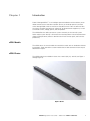
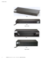
ePDU Photos
The ePDU models are available in three sizes: zero U (0U), 1U, and 2U (see Figure 1
through Figure 3).
Figure 1. 0U Size
EATON Managed ePDUt User’s Guide S 164201xxx Rev 1 DRAFT 10−OCT−2008
1
INTRODUCTION
Front
Back
Figure 2. 1U Size
Front
Back
Figure 3. 2U Size
2
EATON Managed ePDUt User’s Guide S 164201xxx Rev 1 DRAFT 10−OCT−2008
INTRODUCTION
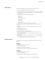
ePDU Features
All models and configurations of the ePDU provide the following features:
S The ability to control outlets collectively and individually
S The ability to power on, power off and reboot the devices connected to each outlet
S The ability to group outlets from multiple ePDUs as virtual outlets accessible from
a single session
S The ability to monitor the following at the outlet level:
− RMS Current
− Power Factor
− Maximum RMS Current
− RMS Voltage
− Active Power
− Apparent power
S The ability to monitor internal CPU temperature of the ePDU
S The ability to monitor environmental factors such as external temperature and
humidity
S An audible alarm (beeper) and a visual alarm (blinking LED) to indicate current
overload
S Configurable alarm thresholds
S Support for SNMP v1, v2 and V3
S The ability to send traps using SNMP protocol
S The ability to retrieve outlet specific data using SNMP, including outlet state,
current, voltage and power
S The ability to configure and set values through SNMP, including ePDU and outlet
threshold levels
S Fully shrouded local branch circuit breakers on products rated over 20A to protect
connected equipments against overload and short circuits
Package Contents
The following describes the equipment and other material included in each model
package.
0U Models
S ePDU including power cord 1.80m (6 ft)
S Bracket for 0U and screws
S Tool−less mounting bracket for 0U models
S Null modem cable with RJ−45 and DB−9F connectors on either end
1U Models
S ePDU including power cord 1.80m (6 ft)
S 1U bracket pack and screws
S Null modem cable with RJ−45 and DB−9F connectors on either end
EATON Managed ePDUt User’s Guide S 164201xxx Rev 1 DRAFT 10−OCT−2008
3
INTRODUCTION
2U Models
S ePDU including power cord 1.80m (6 ft)
S 2U bracket pack and screws
S Null modem cable with RJ−45 and DB−9F connectors on either end
4
EATON Managed ePDUt User’s Guide S 164201xxx Rev 1 DRAFT 10−OCT−2008
Chapter
2
Safety Warnings
IMPORTANT SAFETY INSTRUCTIONS
SAVE THESE INSTRUCTIONS
This manual contains important instructions that you should follow during installation and operation of the
ePDU. Please read all instructions before operating the equipment and save this manual for future reference.
DA N G E R
This ePDU contains
LETHAL VOLTAGES. All repairs and service should be performed
AUTHORIZED
by
SERVICE PERSONNEL ONLY. There areNO USER SERVICEABLE PARTS inside the ePDU.
SYSTEMS SHOULD ONLY BE CONFIGURED BY A COMPETENT PERSON.
IT IS ESSENTIAL THAT THIS EQUIPMENT IS CONNECTED TO AN ELECTRICAL SUPPLY THAT
A HAS
PROTECTIVEGROUNDCONDUCTOR
WARNING: TO ISOLATE THIS EQUIPMENT DISCONNECT POWER SUPPLY PLUG.
ATTENTION: AFIN D’ISOLER TOTALEMENT CET APPAREIL DEBRANCHER FICHE D’ALIMENTATION.
CAUTION: USE ONLY IN DRY LOCATIONS.
ATTENTION: UTILISER UNIQUEMENT DANS DES EMPLACEMENTS SECS.
W ARNI NG
To avoid potentially fatal shock hazard and possible damage to Eaton equipment:
Do not use a 2−wire power cord in any product configuration.
Test AC outlets at your computer and monitor for proper polarity and grounding.
Use only with grounded outlets at both the computer and monitor. When using a backup UPS, power the
computer, monitor and appliance off the supply.
The installation socket outlet used for the power supply to this equipment must be installed near the
equipment
andmustbe easilyaccessible.
When installing this product, it is essential that the distribution circuit supplying the product is protected
by a branch circuit protection device with a maximum rating to suit the product maximum rating.
TO ISOLATE THIS EQUIPMENT DISCONNECT POWER SUPPLY PLUG.
This power distribution unit is intended for power supply provision to equipment only. Secondary
(Satellite) power strips shall not be connected to the receptacles.
This product has been designed to conform to the latest safety requirements. In addition to compliance
with standards for general use, it has been factory configured for use in rack mounting environments
aiding the installer to provide systems compliant with relevant standards.
EATON
Managed ePDU
User’s Guide
164201xxx Rev
1 DRAFT
10−OCT−2008
5
SAFETY WARNINGS
6
EATON Managed ePDUt User’s Guide S 164201xxx Rev 1 DRAFT 10−OCT−2008
Chapter
3
Rack−Mounting the ePDU
Mount Safety Guidelines
In Eaton products which require rack mounting, please follow these precautions:
Operation temperature in a closed rack environment may be greater than 40°C .
Do not exceed the rated maximum ambient temperature of the
appliances (see Appendix E: Specifications).
Ensure sufficient airflow through the rack environment.
Mount equipment in the rack carefully to avoid uneven mechanical loading.
Connect equipment to the supply circuit carefully to avoid overloading circuits.
Ground all equipment properly, especially supply connections, such as power strips
(other than direct connections), to the branch circuit.
Zero−U models are provided with high−grade engineering polycarbonate isolation
hardware to allow fixing in a variety of positions within the rack.
For panel or flush mount, pull−out fixing brackets are available on each end cap to
allow mounting on suitable rails (see Figure 4).
Figure 4. Pull−Out Fixing Brackets
EATON
Managed ePDU
User’s Guide
164201xxx Rev
1 DRAFT
10−OCT−2008
7
RACK−MOUNTING THE EPDU
See Figure 5 through Figure 7 for other options.
Figure 5. Side Fixing
Figure 6. End Fixing
Figure 7. Blind Fixing
NOTE For side and blind fixing:
S Do not repeatedly slide the bracket along the extrusion. This may degrade the support capability.
S For larger/heavier power strips more than one pair of clip fixings may be used.
8
EATON Managed ePDUt User’s Guide S 164201xxx Rev 1 DRAFT 10−OCT−2008
RACK−MOUNTING THE EPDU
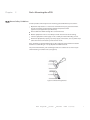
Mounting Instructions
The 0U models also ship with a tool−less mounting kit consisting of a claw feet with
silver button on one side. These work by attaching to the back side of a 0U ePDU (the
side opposite of the outlets) and fitting the button into the mounting holes of the
cabinet. Note that not all racks allow the option of securing the ePDU in this way.
a
Before beginning:
Ensure that you have sufficient space in the cabinet to mount the ePDU.
Approximately one inch of clearance is required at each end (top and bottom) of
the ePDU.
It may help to mark the back of the ePDU through the mounting holes you intend
to use. You can then use this mark to assist in aligning the silver buttons properly
when attaching the claw−feet.
To mount:
1.
Snap fit the claw feet mounts onto the back of the ePDU. Hook one side of the
ePDU body into one side of a claw foot first, and then apply pressure to snap in
the second side. Figure 8 shows how firm pressure is applied to snap fit the claw
feet to the ePDU 0U model.
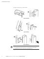
Leave at least 610 mm between the buttons for stability. Once the claw feet
are mounted on the ePDU rail, they will not readily move. A flat−head screwdriver
can be used to remove the feet if they need to be repositioned.
Firm Pressure
Click
Figure 8. Snap Fit to Claw Foot
2.
Align the silver buttons with the mounting holes in the cabinet, and ensure that
both buttons can engage their mounting holes simultaneously.
3.
Press the ePDU forward, pushing the silver buttons through the mounting holes,
then letting the ePDU drop about 16 mm. This secures the ePDU in
place and completes the installation.
EATON
Managed ePDU
User’s Guide
164201xxx Rev
1 DRAFT
10−OCT−2008
9
RACK−MOUNTING THE EPDU
10
EATON Managed ePDUt User’s Guide S 164201xxx Rev 1 DRAFT 10−OCT−2008
Chapter 4
Installation and Configuration
This chapter explains how to install a ePDU and configure it for network connectivity.
Before You Begin
Before beginning the installation, perform the activities listed below:
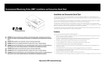
Unpack the ePDU and Components
1.
Remove the ePDU and other equipment from the box in which they were
shipped. See Package Contents" on page 3 for a complete list of the contents
of the box.
2.
Compare the model and serial number of the equipment with the number on the
packing slip located on the outside of the box and make sure they match.
3.
Inspect the equipment carefully. If any of the equipment is damaged or missing,
contact your Eaton service representative for assistance.
Prepare the Installation Site
1.
Make sure the installation area is clean and free of extreme temperatures and
humidity.
2.
Allow sufficient space around the ePDU for cabling and outlet connections.
3.
Review the Safety Instructions" in Chapter 2.
Fill Out the Equipment Setup Worksheet
An Equipment Setup Worksheet is provided in Chapter 9, Appendix A. Use this
worksheet to record the model, serial number, and use of each device connected to
the ePDU.
As you add and remove devices, keep the worksheet up to date.
EATON Managed ePDUt User’s Guide S 164201xxx Rev 1 DRAFT 10−OCT−2008
11
INSTALLATION AND CONFIGURATION
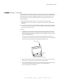
Connect the ePDU to a Computer
You must connect the ePDU to a computer to configure it. This is done by means of a
serial connection between the ePDU and the computer. If you plan to use this
connection to log into the CLP command line interface, leave the cable connected
after the configuration is complete.
The computer must have a communications program such as HyperTerminalt,
Kermit, or PuTTy. You also need the null modem cable and connectors that were
shipped with the ePDU.
1.
Take the null modem cable and connect the end with the RJ−45 connector to the
port labeled Serial" on the front of the ePDU (see Figure 9 through Figure 11).
Serial
Feature
LAN
Figure 9. 0U ePDU Ports
Serial
LAN
Feature
Figure 10. 1U ePDU Ports
Serial
LAN
Feature
Figure 11. 2U ePDU Ports
2.
12
Plug the other end of the null modem cable (containing the DB−9 connector) into
the serial port (COM) of the computer.
EATON Managed ePDUt User’s Guide S 164201xxx Rev 1 DRAFT 10−OCT−2008
INSTALLATION AND CONFIGURATION
the ePDU to Your Network
To use the Web interface to administer the ePDU, you must connect the ePDU to
your local area network (LAN).
1.
Take a standard Category 5e UTP cable and connect one end to the LAN port on
the front of the ePDU.
NOTE
2.
See Figure 9 through Figure 11 for the location of the LAN port on your size ePDU.
Connect the other end of the cable to your LAN.
the ePDU for Network Connectivity
You have two options:
Connect immediately to your LAN for the device to communicate with your DHCP server and
allocate an address. If using DHCP then this finishes the installation.
Or
Connect the serial configuration cable from the ePDU to the device and follow the below
1. Go to the computer that you connected to the ePDU and open a communications
program such as HyperTerminal or PuTTy. Make sure the port settings are
configured as follows:
Bits per second = 9600
Data bits = 8
Stop bits = 1
Parity = None
Flow control = None
NOTE The ˆFlow control˜ parameter must be set to ˆNone˜ for the communications program to work
correctly with the ePDU.
2.
Point the communications program at the serial port connecting the ePDU and
open a terminal window.
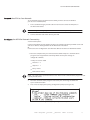
3.
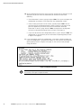
Press Enter to display the opening configuration prompt (see Figure 12).
Figure 12. Opening Configuration Prompt
EATON
Managed ePDU
User’s Guide
164201xxx Rev
1 DRAFT
10−OCT−2008
13
INSTALLATION AND CONFIGURATION
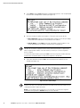
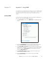
4.
Type config and press Enter to begin the configuration process. You are prompted
to select an IP configuration method (see Figure 13).
Figure 13. IP Configuration Prompt
5.
You must assign the ePDU an IP address. There are two ways to do this:
S Auto configuration: Select an autoconfiguration method such as dhcp or bootp
and let the DHCP or BOOTP server provide the IP address.
S Static IP address: Select None and assign the ePDU a static IP address. You
will be prompted for the address, network mask, and gateway.
NOTE The ePDU IP address displays automatically in the system prompt. The default IP address is
192.168.0.192. The default IP configuration method is DHCP, and the default IP address is replaced by the
address assigned by DHCP or BOOTP, or the static IP address you entered, as soon as the configuration
process is complete.
To use the factory default IP address, please type in none as the IP autoconfiguration command, and accept
the default value. The default IP address for static (none) configuration is 192.168.0.192.
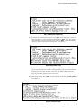
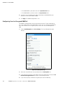
6.
Type your selection and press Enter. You are prompted to enable IP access
control (see Figure 14).
Figure 14. Access Control Prompt
NOTE By default, IP access control is NOT enabled. This disables the ePDU firewall. Leave the firewall
disabled for now. Later on, you can enable the firewall from the Web interface and create firewall rules (see
Configuring the Firewall" on page 39 for details).
NOTE If you accidentally create a rule that locks you out of the ePDU, you can rerun the configuration
program and reset this parameter to disabled to allow you to access the ePDU.
14
EATON Managed ePDUt User’s Guide S 164201xxx Rev 1 DRAFT 10−OCT−2008
INSTALLATION AND CONFIGURATION
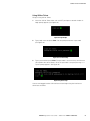
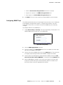
7.
Press Enter. You are prompted to set the LAN interface speed (see Figure 15).
Figure 15. LAN Interface Speed Prompt
8.
By default, the LAN interface speed is set to Auto, which allows the system to
select the optimum speed. To keep the default, press Enter. To set the speed to
10 or 100 Mbps, type the speed you want and press Enter. You are prompted to
select the duplex mode for the LAN interface. See Figure 16.
Figure 16. Duplex Mode Prompt
By default, the LAN interface duplex mode is set to Auto, which allows the
system to pick the optimum mode. Half duplex allows data to be transmitted to
and from the ePDU, but not at the same time. Full duplex allows data to be
transmitted in both directions at the same time.
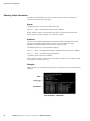
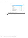
9.
To keep the default, press Enter. To specify half or full duplex, type half or full and
press Enter. You are prompted to confirm the information you just entered
(see Figure 17).
Figure 17. Confirmation Prompt
EATON Managed ePDUt User’s Guide S 164201xxx Rev 1 DRAFT 10−OCT−2008
15
INSTALLATION AND CONFIGURATION
10. All the configuration parameters have now been entered. All the prompts are still
displayed, so you can check the information you entered. Do one of the
following:
S If the information is correct, type y and press Enter. The system completes the
configuration and displays a message when the configuration is done.
S If one or more parameters are not correct, type n and press Enter. You are
returned to the IP configuration prompt shown in Figure 13 on page 14 and
given the opportunity to correct each piece of information. When the
information is correct, type y and press Enter to complete the configuration
and return to the opening prompt shown in Figure 12 on page 13.
S If you want to terminate the configuration process, type c and press Enter. The
configuration is cancelled and you are returned to the opening prompt shown
in Figure 12 on page 13.
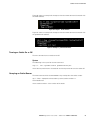
11. If you entered y to confirm the configuration, a message is displayed telling you
when the configuration is complete (see Figure 18). You are then returned to the
opening prompt shown in Figure 12 on page 13. You are now ready to begin
using your ePDU.
Figure 18. Configuration Complete
NOTE The configured IP address takes about 15 seconds to take effect for the device connected through
the serial line, or even longer if configured over DHCP.
16
EATON Managed ePDUt User’s Guide S 164201xxx Rev 1 DRAFT 10−OCT−2008
INSTALLATION AND CONFIGURATION
Resetting to Factory Defaults
CAUTION
Exercise extreme caution before resetting the ePDU to the factory defaults. This wipes out any information
you have entered, including user profiles, user groups, thresholds, alert policies, and so forth.
For security reasons the ePDU may only be restored to defaults at the local serial
console. To do this:
1.
Connect a computer to the serial port of the ePDU
2.
Using a terminal emulation program such as HyperTerminal, Kermit, or PuTTY (at
a speed of 9600 bps), open a window on the ePDU.
NOTE About HyperTerminal and PuTTy terminal emulator applications:
S HyperTerminal is available on many of Windows® operating systems. But HyperTerminal is not available
on the Windows Vista ® operating system.
S PuTTY is a free program you can download from the internet. Please refer to PuTTY documentation for
details on configuration.
Make sure the serial port settings are configured as follows:
S Baud rate (bits per second) = 9600
S Data bits = 8
S Stop bits = 1
S Parity = None
S Flow control = None
3.
Press and release the Reset button of the ePDU while pressing the [Esc] key
several times in rapid succession. A prompt (=>) should appear after about
one second.
4.
Execute the Defaults command to reset the ePDU to the factory defaults.
NOTE Enter help to show a list of available commands and a short description of each one.
Figure 19 shows the location of the reset hole for the 1U and 2U models.
Figure 20 shows the reset hole for the 0U model.
EATON Managed ePDUt User’s Guide S 164201xxx Rev 1 DRAFT 10−OCT−2008
17
INSTALLATION AND CONFIGURATION
Reset Hole
Figure 19. Reset Hole (1U and 2U Models)
Reset Hole
Figure 20. Reset Hole (0U Models)
18
EATON Managed ePDUt User’s Guide S 164201xxx Rev 1 DRAFT 10−OCT−2008
Chapter 5
Using the ePDU
This chapter explains how to use the ePDU. It describes the LEDs and ports on the
front and back panels of the ePDU, and explains how to use the display panel. It also
explains how the circuit breaker works and when the beeper goes off.
Front Panel
The front panel of the 1U and 2U ePDU models consists of a blue LED to the right
and three connection ports to the left. The front panel of the 0U model consists of
power outlets to connect devices to the ePDU, a display panel, a recessed reset
button, and three connection ports.
Ethernet Ports
The three RJ−45 Ethernet ports, from left to right, are labeled Serial, Feature, and
LAN. Table 1 explains what each port is used for.
Table 1. Ethernet Ports
Port
Purpose
Serial
Establishing a serial connection between a computer and the ePDU.
Take the null modem cable that was shipped with the ePDU , connect the end with the
RJ−45 connector to the port labeled Serial on the front of the ePDU, and connect the
end with the DB−9F connector to the serial (COM) port on the computer.
Feature
For use with Eaton−provided environmental sensors.
LAN
Connecting the ePDU to your company’s network.
Connect a standard Category 5e UTP cable to this port and connect the other end to
your network. This connection is necessary to administer the ePDU remotely using the
Web interface.
There are two small LEDs under the LAN port. Green indicates a physical link and
activity, and yellow indicates communication at 10/100 BaseT speeds.
Blue LED
Only the 1U and 2U models have a blue LED on the front panel. The blue LED on the
right side of the front panel is lit solid when the ePDU is plugged in.
NOTE If the blue LED is flashing, one of the two power supplies in the ePDU is not functional.
NOTE When the ePDU is powered on, the power−on self test and software loading takes approximately
40 seconds. Once the software has booted up, the outlet LEDs and the meter illuminate.
EATON Managed ePDUt User’s Guide S 164201xxx Rev 1 DRAFT 10−OCT−2008
19
USING THE EPDU
Back Panel
The back panel of the 1U and 2U ePDUs consist of, from left to right, a power cord,
power outlets to connect devices to the ePDU, and a display panel. Zero−U models do
not have a back panel.
Power Cord
The power cord that connects the ePDU to a power source is located on the far left of
the back panel, or on the end of the ePDU if the ePDU is a 0U model. All devices are
non−rewireable by the user.
NOTE Each ePDU should be plugged into an appropriately rated outlet for its type.
There is no power switch on the ePDU. On models rated at over 20A, there are
branch circuit breakers that are fully shrouded to prevent accidental operation. To
power cycle the ePDU, remove the power cord from the power source and then
re−connect it.
Outlets
The number of outlets on the back panel depends upon the ePDU model. To the
upper left of each outlet is a small LED. The ePDUs are shipped from the factory with
all outlets powered ON.
Table 2 explains how to interpret the different LED states.
Table 2. LED Status
LED State
Outlet Status
What it Means
Not lit
ePDU OFF
The outlet is not connected to power or the control circuitry’s
power supply is broken.
Red
ON and LIVE
The outlet is ON (relay closed) and LIVE (voltage present).
Red flashing
ON and LIVE
The outlet is ON and LIVE, but there is overload and the
current has crossed the non−critical threshold.
Green
OFF and LIVE
The outlet is OFF (relay open) and the ePDU is LIVE.
Green flashing
OFF and NOT LIVE
The outlet is OFF and the supply is not present.
Yellow flashing
ON and NOT LIVE
The outlet is ON but NOT LIVE (circuit breaker open or other
high voltage rail error).
Cycling through
Red, Green and
Yellow
Indicates one of two possibilities:
S The ePDU has just been plugged in and its management
software is loading.
S A firmware upgrade is being performed on the ePDU
NOTE When a ePDUis powered on, the power−on self−test and software loading takes a few moments. As
the ePDU boots up, the outlet LEDs cycle through red, green and yellow. When the software has completed
loading, the outlet LEDs displays a steady color and the meter illuminates.
20
EATON Managed ePDUt User’s Guide S 164201xxx Rev 1 DRAFT 10−OCT−2008
USING THE EPDU
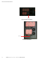
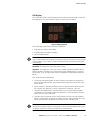
LED Display
The LED display panel is located adjacent to the outlets on the 0U model, and on the
back right of the 1U and 2U models. Figure 21 shows the LED display.
Figure 21. LED Display Panel
The LED display panel consists of these components:
S A top row that displays three digits
S A bottom row that displays two digits
S UP and DOWN buttons
NOTE The small hole between the lower row and the Down button is the Reset hole. The ePDU can be
reset to its factory default values through this hole only when connected to the serial port. See the Resetting
to Factory Defaults" section on page 17 for additional configuration details. Pressing the Reset button ONLY
restarts the ePDU.
Lower Row: The lower row shows the outlet number.
Upper Row: The upper row shows the current, voltage, and power readings for the
outlet indicated in the lower row. During the firmware upgrade process, the upper
row displays ˆFuP˜ to indicate that a Firmware Upgrade is being performed on the
ePDU.
How to Operate the Display Panel:
S Use the Up and Down buttons to select an outlet. Pressing the Up button once
moves up one outlet number. Pressing the Down button once moves down one
outlet number.
S When an outlet is selected, the outlet number is displayed in the lower row and
the current in the upper row. Current is displayed in the format: XX.X (A).
S To display the voltage for the selected outlet, press the Up and Down buttons
simultaneously. The voltage reading will replace the current for about 5 seconds,
after which the current will return.
S To display the active power for the selected outlet, first press the Up and Down
buttons simultaneously to display the voltage, and then again to display the active
power. Active Power is displayed in the format: X.XX in volt−amps (VA).
NOTE Tip: A quick way to distinguish between voltage, current, and power is the placement of the
decimal point in the display. Voltage has no decimal point, current has a decimal point between the first and
second digits, and power has a decimal point between the second and third digits.
EATON Managed ePDUt User’s Guide S 164201xxx Rev 1 DRAFT 10−OCT−2008
21
USING THE EPDU
Breaker
The ePDU includes branch circuit breakers that automatically trip when a power
overload is detected. The ePDU standard circuit breakers have Type C trip
characteristics. If the circuit breaker switches off the voltage rail, the lower row of the
display panel will jump to the lowest outlet number affected by the circuit breaker
error, and the upper row will display these three letters, which indicate a circuit
breaker error:
CbE
You will still be able to switch between outlets on the ePDU display panel. Outlets
affected by the error show CbE. Unaffected outlets show the current and voltage
readings as described above.
To reset the breakers in the event of an overload:
On the 1U and 2U models, unclip the front molding to access the breaker(s).
On the 0U model, the breaker(s) can be accessed by lifting the hinged cover over
the breaker element.
The ePDU includes a beeper. The beeper rings if any of the circuit breakers are
tripped or if the control board temperature sensor exceeds 80
°C (176 °F).
The beeper will cease ringing when the broken circuit breaker conditions disappear or
the control board temperature sensor drops below 70 °C (158 °F).
The temperature thresholds are factory defaults, and can be user−configurable.
It takes a maximum of three seconds for the beeper to start ringing after the circuit
breaker has been tripped.
Accuracy
Voltage (per outlet): Range 0–255V, ± 5%, 3 digits, resolution 1V
Current (per outlet): Range 0–25.5A, ± 5%, 3 digits, resolution 0.1A
22
EATON
Managed ePDU
User’s Guide
164201xxx Rev
1 DRAFT
10−OCT−2008
Chapter 6
Using the Web Interface
This chapter explains how to use the Web interface to administer a ePDU.
Logging into the Web Interface
To log into the Web interface, you must enter a user name and password. The first
time you log in, use the default user name (admin) and password (pass). You will then
be prompted to change the password for security purposes.
Once you have logged in, you can create user profiles for your other users. These
profiles define their login names and passwords. (See Creating a User Profile" on
page 32.)
Logging In
To log into the Web interface:
1.
Open a browser such as Microsoft® Internet Explorer® or Mozilla® Firefox® and
point it to this URL:
http://<ip address>
where <ip address> is the IP address of the ePDU. A login page displays
(see Figure 22).
Figure 22. Login Page
2.
Type your user name and password in the Username and Password fields. Both
the user name and password are case−sensitive, so make sure you capitalize the
letters correctly.
EATON Managed ePDUt User’s Guide S 164201xxx Rev 1 DRAFT 10−OCT−2008
23
USING THE WEB INTERFACE
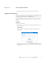
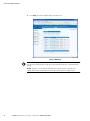
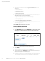
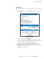
3.
Click Login. The Home page displays (see Figure 23).
ePDU
Figure 23. Home Page
NOTE The Home page example in Figure 23 shows 8 outlets. If your ePDU has 20 outlets, the Home page
will show 20. See Outlets Display" on Page 30 for a more information and pictures of both 8 and 20 outlet
displays.
NOTE JavaScriptt must be enabled in the Web browser for proper operation. If JavaScript is not
enabled, features such as the Status Panel on the left side of the interface will not display correctly.
24
EATON Managed ePDUt User’s Guide S 164201xxx Rev 1 DRAFT 10−OCT−2008
USING THE WEB INTERFACE
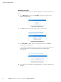
Changing Your Password
To change your password:
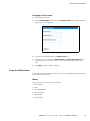
1.
Select User Management, and then select Change Password. The Change Password
page displays (see Figure 24).
Figure 24. Change Password Page
2.
Type your existing password in the Old Password field.
3.
Type your new password in the New Password and Confirm New Password fields.
Passwords are case sensitive, so be sure to capitalize the same letters each
time.
4.
Click Apply. Your password is changed.
Using the Web Interface
Every page in the Web interface provides menus and a navigation path across the top,
and a status panel to the left.
Menus
There are several menus in the Web interface:
S Power Outlets
S Alerts
S User Management
S Device Settings
S Maintenance
S Outlet Groups
EATON Managed ePDUt User’s Guide S 164201xxx Rev 1 DRAFT 10−OCT−2008
25
USING THE WEB INTERFACE
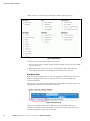
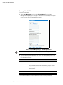
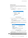
Figure 25 shows a complete list of the options available from each menu.
Figure 25. Menu Options
There are two ways to select an option from a menu:
S Click the menu name to display a page listing each option, and then click the option
you want to select.
S Position the cursor on the menu name. A list of options drops down from the
menu. Move your pointer to the option you want and click it to select it.
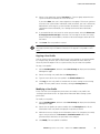
Navigation Path
When you select an option from a menu and navigate to a specific page, the system
displays a navigation path across the top that shows the menu and option you
selected to get there.
For example, if you select User Management > User/Group System Permissions, the
navigation path looks like the one shown in Figure 26.
Figure 26. Navigation Path
To return to a previous page, click the page name in the navigation path. Every
navigation path begins at the Home page, so a single click always takes you back to
the Home page from anywhere in the interface.
26
EATON Managed ePDUt User’s Guide S 164201xxx Rev 1 DRAFT 10−OCT−2008
USING THE WEB INTERFACE
Status Panel
The Status panel displays on the left of every page in the interface (see Figure 27). It
shows:
S Current date and time
S Information about the user, including:
− User name
− User’s current state (active, idle, and so forth)
− IP address of the user’s computer
− Date and time of the user’s last login
S Information about the ePDU, including:
− Model name and number
− IP address
− Firmware version
S Information about all the users currently connected, including:
− User name
− IP address
− Current state
Your current session is included in this list.
S A link to the User’s Guide on the Eaton Web site.
ePDU
Figure 27. Status Panel
The State field in the user information section considers a user to be idle 30 seconds
after the last keyboard or mouse action. It then updates the idle time every 10
seconds until another keyboard or mouse action is detected.
If you exceed the idle time limit, you will be logged out, and redirected to the main
login page automatically.
EATON Managed ePDUt User’s Guide S 164201xxx Rev 1 DRAFT 10−OCT−2008
27
USING THE WEB INTERFACE
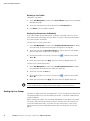
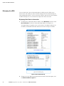
Status Messages
When you perform an operation from the Web interface, such as creating a user
profile or changing a network setting, a message displays at the top of the page
indicating whether or not the operation was successful. Be sure to check this
message to confirm that an operation was successful.
Figure 28 shows two examples of status messages after an operation has completed
successfully.
Figure 28. Status Messages (Operation Successful)
Figure 29 shows two examples of status messages after an operation has completed
unsuccessfully.
Figure 29. Status Messages (Operation Unsuccessful)
Unavailable Options
At times, certain actions will be unavailable. When this occurs, the appropriate
buttons will be non−functional, though different browsers may display this differently.
For example: if you select the Admin User Group in Internet Explorer, the buttons for
Copy, Modify and Delete will be dimmed since you cannot Copy, Modify or Delete
the Admin user group. In Firefox, however, these non−functioning buttons display
normally.
28
EATON Managed ePDUt User’s Guide S 164201xxx Rev 1 DRAFT 10−OCT−2008
USING THE WEB INTERFACE
Reset to Defaults
Many pages provide a Reset to Defaults button that returns all fields to their default
values. If you use this button, you must click the Apply button afterward. This saves
the defaults. If you neglect to do this, the next time you return to the page, you will
still see the non−default values.
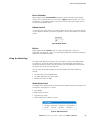
Default Asterisk
If a field has an asterisk after it, as shown in Figure 30, the value is set to the default.
If you change the default, the asterisk disappears. If you reset to defaults, the asterisk
returns.
Figure 30. Default Asterisk
Refresh
Many pages provide a Refresh button. If a page is displayed for a while, the
information may become stale." Click this button periodically to reload the page and
update the information displayed.
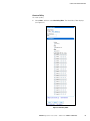
Using the Home Page
The Home page displays first after a successful login. It consists of a Global Status,
an Outlets list, and an All Outlets Control panel. The Home page also contains an
environmental sensors panel, and a time stamp in the top right corner, noting when
the data on the screen was last refreshed.
You can return to the Home page from any other page in the Web interface by
clicking:
S The Home link in the navigation path
S The Eaton logo above the Status panel
S Model name under the logo
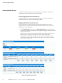
Global Status Panel
The Global Status panel provides an overview of the ePDU’s power consumption and
temperature. See Figure 31. It shows:
S Unit voltage
S RMS current (in amps)
S True power (in watts)
S CPU temperature (in degrees Celsius)
Figure 31. Global Status Panel
EATON Managed ePDUt User’s Guide S 164201xxx Rev 1 DRAFT 10−OCT−2008
29
USING THE WEB INTERFACE
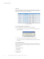
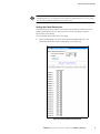
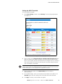
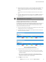
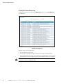
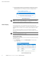
Outlets List
The Outlets List displays each outlet on the ePDU as a table row with a view of the
power status, the RMS current and the Active Power through the individual outlet.(see
Figure 32). for an 8-outlet and for a 20−outlet display.
Figure 32. Outlets List
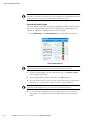
Turn an Outlet On, Off, or Cycle the Power
To turn an outlet ON, OFF or cycle the power to it, do the following:
Click the On, Off, or Cycle in the outlet row. You will be asked to confirm your
action (see Figure 33).
1.
Figure 33. Confirmation Dialog Box
Click OK. The outlet will then switch ON, OFF, or will cycle its power.
2.
You can also turn an outlet on or off from the Outlet Details page (see Figure 54
on page 58).
Display Additional Details
To display additional details about an outlet, click the outlet icon. This displays the
Outlet Details page (see Figure 54 on page 58). This page gives the name and status
of the outlet, as well as:
RMS Current
Maximum RMS Current
RMS Voltage
Active Power
Apparent Power
Power Factor
30
EATON
Managed ePDU
User’s Guide
164201xxx Rev
1 DRAFT
10−OCT−2008
USING THE WEB INTERFACE
NOTE RMS refers to root mean square, a statistical method for measuring certain types of variables. In this
context, it gives the value of current or voltage that is equivalent to a comparable DC value.
All Outlets Control
The All Outlets Control panel at the bottom of the Home page allows you to turn all
outlets ON and OFF. Click On to turn all outlets ON, click Off to turn all outlets OFF. As
with individual outlets, you must confirm the selection before it takes effect.
Figure 34.
NOTE Users must have permission to access all outlets in order to use All Outlets Control.
Setting Up User Profiles
The ePDU is shipped with one user profile built in. This is the admin profile, which
was used for the original login. This profile has full system and outlet permissions,
and should be reserved for the system administrator. This profile cannot be modified
or deleted.
All users must have a user profile. The profile specifies a login name and password,
and contains additional (optional) information about the user. It also assigns the user
to a user group, and the user group determines the user’s system and outlet
permissions.
If you choose, you can refrain from assigning some or all users to a user group, and
instead assign their system and outlets permissions on an individual basis.
NOTE By default, multiple users can log in at the same time using the login name from the same profile.
You can change this so only one user at a time can use a specific login. This is done by selecting
Device Settings > Security and selecting the Enable Single Login Limitation check box.
EATON Managed ePDUt User’s Guide S 164201xxx Rev 1 DRAFT 10−OCT−2008
31
USING THE WEB INTERFACE
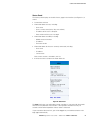
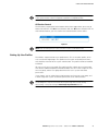
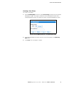
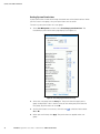
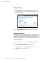
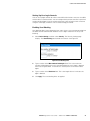
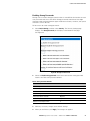
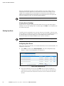
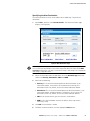
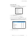
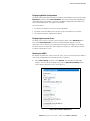
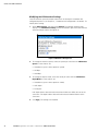
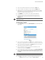
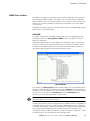
Creating a User Profile
To create a user profile:
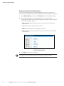
1.
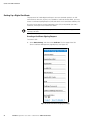
Select User Management, and then select Users & Groups. The User/Group
Management page displays. This page is divided into a User Management panel
(see Figure 35) and a Group Management panel.
Figure 35. User/Group Management page − User Management Panel
NOTE Before entering any information in the user profile, please make sure the user group is created and
available for selection.
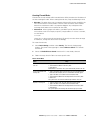
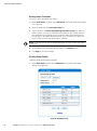
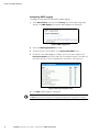
2.
Type the following information about the user in the corresponding fields in the
User Management panel:
Fields
Enter
New User Name
The name the user will enter to log into the Web interface.
Full Name
The user’s first and last name.
Password
The password the user will enter to log in.
The password must be at least four characters long, and spaces are not
permitted. The password is case sensitive, so be sure to capitalize the same
letters each time.
Confirm Password
Reenter the user’s password.
Email Address
An email address where the user can be reached.
Mobile Number
A cell phone number where the user can be reached.
NOTE The New User Name, Password, and Confirm Password are the only required fields.
32
EATON Managed ePDUt User’s Guide S 164201xxx Rev 1 DRAFT 10−OCT−2008
USING THE WEB INTERFACE
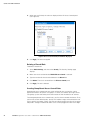
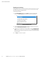
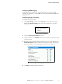
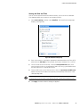
3.
Select a user group from the the User Group list. The user group determines the
system functions and outlets this user can access.
If you select None, the user is not assigned to a user group. This means you have
to set the user’s permissions individually. Until you do this, the user is effectively
blocked from accessing any system functions and outlets. (For instructions on
setting permissions individually, see Setting User Permissions Individually"
below.)
4.
If you would like this user to set his or her own password, select the Enforce user
to change password on next login. check box. The user logs in the first time using
the password you entered above, and then is forced to change it to one of his or
her choice.
5.
Click Create. The user profile is created.
NOTE The Use Password as Encryption Phrase, SNMP v3 Encryption Phrase, and Confirm SNMP Encryption
Phrase apply only when using secure SNMP v3 communication. See Appendix C − Using SNMP" for more
details.
Copying a User Profile
You can create a new user profile with the exact same settings as an existing profile
by using the copy function. You can then modify the profile so that it differs as
necessary from the original. This is a quick and easy way to create user profiles.
To copy a user profile:
1.
Select User Management, and then select Users & Groups to display the User/Group
Management page.
2.
Select an existing user profile from the Existing Users list.
3.
Type the name of the new user profile in the New User Name field.
4.
Click Copy. A new user profile is created with the same settings as the existing
profile. The new profile can be viewed by clicking the Existing Users list.
Modifying a User Profile
Every user with user management permissions can modify a user profile. See
Setting System Permissions" on page 36 for information about setting system
permissions.
To modify a user profile:
1.
Select User Management, and then select Users & Groups to display the User/Group
Management page.
2.
Select the user profile you want to modify from the Existing Users list. All the
information in the user profile is displayed except the password.
3.
Make all necessary changes to the information shown. To change the password,
type a new password in the Password and Confirm Password fields. If the
password field is left blank, the password is not changed.
4.
Click Modify. The user profile is modified.
EATON Managed ePDUt User’s Guide S 164201xxx Rev 1 DRAFT 10−OCT−2008
33
USING THE WEB INTERFACE
Deleting a User Profile
To delete a user profile:
1.
Select User Management, and then select Users & Groups to display the User/Group
Management page.
2.
Select the user profile you want to delete from the Existing Users list.
3.
Click Delete. The user profile is deleted.
Setting User Permissions Individually
If you selected None for user group when creating a user profile, you must set the
user’s permissions individually. Until you do this, the user is effectively blocked from
all system functions and outlets.
To set the user’s system permissions:
1.
Select User Management, and then select User/Group System Permissions to display
the User Group System Permissions page (see Figure 37 on page 36).
2.
Select the user from the User (not in a group) list. The list shows all user profiles
that have NOT been assigned to a users group.
3.
Set the permissions as necessary. Click this icon
Yes or No.
4.
When you are finished, click Apply. The permissions are applied to the user.
in a field and select either
To set the user’s outlet permissions:
1.
Select User Management, and then select User/Group Outlet Permissions to display
the User/Group Outlet Permissions page (see Figure 38).
2.
Select the user from the User list.
3.
Set the permissions as necessary. Click this icon
Yes or No.
4.
When you are finished, click Apply. The permissions are applied to the user.
in a field and select either
NOTE IPMI privilege level user" is the minimum level required to switch outlets over IPMI, which causes
no effect on Web front-end use. However, privilege level has nothing to do with outlet permissions.
Setting Up User Groups
The ePDU is shipped with one user group built in. This is the Admin User Group. This
user group provides full system and outlet permissions. It cannot be modified and it
cannot be deleted.
When creating user profiles, the User Group field defaults to the Admin User Group.
This means that if you do not change the entry in this field, the user will enjoy full
system and outlet permissions. To restrict the user’s permissions, create a user
group with limited system and/or outlet permissions, and assign the user to that
group.
34
EATON Managed ePDUt User’s Guide S 164201xxx Rev 1 DRAFT 10−OCT−2008
USING THE WEB INTERFACE
Creating a User Group
To create a user group:
1.
Select User Management, and then select Users & Groups to display the User/Group
Management page. This page is divided into a User Management panel and a
Group Management panel. See Figure 36 shows the Group Management panel.
Figure 36. User Group Management page − Group Management Panel
2.
In the Group Management panel, type the name of the group in the New Group
Name field.
3.
Click Create. The user group is created.
EATON Managed ePDUt User’s Guide S 164201xxx Rev 1 DRAFT 10−OCT−2008
35
USING THE WEB INTERFACE
Setting System Permissions
System permissions include all the major functional areas of the Web interface. When
you first create a user group, all system permissions are set to NO.
To set the system permissions for a user group:
1.
Select User Management, and then select Users/Group System Permissions. The
User/Group System Permissions page displays (see Figure 37).
Figure 37. User/Group System Permissions Page
36
2.
Select the user group from the Group list. The permissions that apply to this
group are displayed. If this is the first time you are setting the permissions for
this group, all permissions are set to No.
3.
Set the permissions as necessary. Click this icon
Yes or No.
4.
When you are finished, click Apply. The permissions are applied to the user
group.
EATON Managed ePDUt User’s Guide S 164201xxx Rev 1 DRAFT 10−OCT−2008
in a field and select either
USING THE WEB INTERFACE
NOTE The User (not in a group) list on this page is used to set individual user permissions. If you are
setting group permissions, you may ignore this field. Furthermore, if IPMI privilege level is not set to at least
user" level, this group will not be granted to perform power control.
Setting the Outlet Permissions
Setting outlet permissions allows you to specify which outlets members of a user
group are permitted to access. When you first create a user group, all outlet
permissions are set to NO.
To set the outlet permissions for a user group:
1.
Select User Management, and then select Users/Group Outlet Permissions. The
User/Group Outlet Permissions page displays (see Figure 38).
Figure 38. User/Group Outlet Permissions Page
EATON Managed ePDUt User’s Guide S 164201xxx Rev 1 DRAFT 10−OCT−2008
37
USING THE WEB INTERFACE
2.
Select the user group from the Group list. The permissions that apply to this
group are displayed. If this is the first time you are setting the permissions for
this group, all permissions are set to No.
3.
Set the permissions as necessary. Click this icon
Yes or No.
4.
When you are finished, click Apply. The permissions are applied to the user
group.
in a field and select either
NOTE The User (not in a group) list on this page is used to set individual user permissions. If you are
setting group permissions, you may ignore this field.
Copying a User Group
You can create a new user group with the exact same permissions as an existing user
group by using the copy function. You can then modify the group so that its
permissions differ as necessary from the original. This is a quick and easy way to
create user groups.
To copy a user group:
1.
Select User Management, and then select Users & Groups. The User/Group
Management page displays.
2.
Select the existing user group from the Existing Groups list.
3.
Type the name of the new user group in the New Group Name field.
4.
Click Copy. A new user group is created with the same permissions as the
existing group. The new user group can be viewed by clicking the Existing Groups
list.
Modifying a User Group
The only attribute of a user group that can be modified is the group name. To do this:
1.
Select User Management, and then select Users & Groups. The User/Group
Management page displays.
2.
Select the user group you want to modify from the Existing Groups list. The name
displays in the New Group Name field.
3.
Make any necessary changes to the name.
4.
Click Modify. The user group is modified.
NOTE To modify a user group’s system or outlet permissions, repeat the procedure for setting the system
or outlet permissions described above and make any necessary changes.
38
EATON Managed ePDUt User’s Guide S 164201xxx Rev 1 DRAFT 10−OCT−2008
USING THE WEB INTERFACE
Deleting a User Group
To delete a user group:
1.
Select User Management, and then select Users & Groups. The User/Group
Management page displays.
2.
Select the user group you want to delete from the Existing Groups list.
3.
Click Delete. The user group is deleted.
Setting Up Access Controls
The ePDU provides a number of tools to control access to the unit. You can require
HTTPS encryption, enable the internal firewall and create firewall rules, and create
login limitations.
Forcing HTTPS Encryption
HTTPS is a more secure protocol than HTTP because it uses Secure Sockets Layer
(SSL) technology to encrypt all traffic to and from the ePDU. To require users to use
HTTPS instead of HTTP when accessing the ePDU through the Web interface:
1.
Select Device Settings, and then select Security. The Security Settings page
displays. The panel at the upper left is labeled HTTP Encryption." See Figure 39.
Figure 39. Security Settings Page – HTTP Encryption Panel
2.
Select the Force HTTPS for Web access check box.
3.
Click Apply. HTTPS is now required for browser access.
NOTE Attempts to access the ePDU using HTTP will be redirected back to HTTPS automatically only if the
Force HTTPS for Web access field is selected.
Configuring the Firewall
The ePDU has a firewall that can be configured to prevent specific IP addresses and
ranges of IP addresses from accessing the ePDU. When the ePDU was initially
configured, you were prompted to enable or disable IP access control. If you selected
Disable (the default), the ePDU firewall was not enabled.
To configure the firewall, you have to enable the firewall, and then you have to set the
default policy and create rules specifying which addresses to accept and which
addresses to drop.
NOTE The purpose of disabling the firewall by default is to prevent users from accidentally locking
themselves out of the ePDU. See Chapter 4, Installation and Configuration," for details.
EATON Managed ePDUt User’s Guide S 164201xxx Rev 1 DRAFT 10−OCT−2008
39
USING THE WEB INTERFACE
Enabling the Firewall
To enable the ePDU firewall:
1.
Select Device Settings, and then select Security. The Security Settings page
displays. The panel at the upper right is labeled IP Access Control. This controls
the firewall. See Figure 40.
Figure 40. IP Access Control Panel (Firewall Enabled)
2.
Select the Enable IP Access Control check box. This enables the firewall.
3.
Click Apply. The firewall is enabled.
Changing the Default Policy
Once enabled, the firewall has a default policy built in that accepts traffic from all IP
addresses. This means any IP addresses not dropped by a specific rule will be
permitted to access the ePDU. You can change the default policy to DROP, in which
case traffic from all IP addresses will be dropped except traffic allowed by a specific
ACCEPT rule.
To change the default policy:
40
1.
Select Device Settings, and then select Security. The Security Settings page
displays. The panel at the upper right is labeled IP Access Control. This controls
the firewall.
2.
Make sure the Enable IP Access Control check box is selected.
3.
The default policy is shown in the Default Policy field (see Figure 40). To change
it, select the policy you want from the drop−down list in the field.
4.
Click Apply. The new default policy is applied.
EATON Managed ePDUt User’s Guide S 164201xxx Rev 1 DRAFT 10−OCT−2008
USING THE WEB INTERFACE
Creating Firewall Rules
Firewall rules accept or drop traffic intended for the ePDU, based on the IP address of
the host sending the traffic. When creating firewall rules, keep the following in mind:
S Rule order: The order of the rules is important. When traffic reaches the ePDU, the
rules are executed in numerical order. The first rule that matches the IP address
determines whether the traffic is accepted or dropped. Any subsequent rules
matching the IP address have no effect on the traffic
S Subnet mask: When typing the IP address, you MUST specify both the address
and a subnet mask. For example, to specify a single address in a Class C network,
use this format:
x.x.x.x/24
where /24 = a subnet mask of 255.255.255.0.To specify an entire subnet or range
of addresses, change the subnet mask accordingly.
To create firewall rules:
1.
Select Device Settings, and then select Security. The Security Settings page
displays. The panel at the upper right is labeled IP Access Control. This controls
the firewall.
2.
Select the Enable IP Access Control check box if it is not already selected.
3.
Follow the steps listed in Table 3 to create specific rules.
Table 3. Create Rules
Action
Steps
Add a rule to the end of the
rules list
S Type an IP address and subnet mask in the IP/Mask field.
S Select ACCEPT or DROP in the Policy field.
S Click Append.
Do NOT enter a rule number. The system automatically numbers the rule.
Insert a rule between two
existing rules
S Type a rule number where you want to insert a new rule above in the
Rule # field. For example, to insert a rule between #5 and #6, type 6.
S Type an IP address and subnet mask in the IP/Mask field.
S Select ACCEPT or DROP from the drop−down list in the Policy field.
S Click Insert.
The system inserts the rule and automatically renumbers the rules.
Replace an existing rule
S Type the number of the rule to be replaced in the Rule # field.
S Type an IP address and subnet mask in the IP/Mask field.
S Select ACCEPT or DROP from the drop−down list in the Policy field.
S Click Replace.
This system replaces the existing rule with the one you just created.
EATON Managed ePDUt User’s Guide S 164201xxx Rev 1 DRAFT 10−OCT−2008
41
USING THE WEB INTERFACE
4.
When you are finished, the rules are displayed in the IP Access Control panel
(see Figure 41).
Figure 41. IP Access Control Panel (Firewall Rules Displayed)
5.
Click Apply. The rules are applied.
Deleting a Firewall Rule
To delete a firewall rule:
1.
Select Device Settings, and then select Security. The Security Settings page
displays.
2.
Make sure the check box labeled Enable IP Access Control is selected.
3.
Type the number of the rule to be deleted in the Rule # field.
4.
Click Delete. The rule is removed from the IP Access Control panel.
5.
Click Apply. The rule is deleted.
Creating Group−Based Access Control Rules
Group−based access control rules are similar to firewall rules, except they can be
applied to members of specific user groups. In effect, this enables you to give entire
user groups system and outlet permissions based on their IP addresses or subnets.
To create group−based access control rules, you first have to enable the feature. Then,
you have to set the default action, specify an IP address range, and associate the rule
with a specific User group. Finally, you have to indicate whether the rule will accept or
drop traffic. Changes made do not affect users currently logged in until the next login.
42
EATON Managed ePDUt User’s Guide S 164201xxx Rev 1 DRAFT 10−OCT−2008
USING THE WEB INTERFACE
Enabling Group−based Access Control Rules
To enable group−based access control rules:
1.
Select Device Settings, and then select Security. The Security Settings page
displays. The panel labeled Group Based System Access Control controls this
feature. See Figure 42.
Figure 42. Group Based System Access Control Panel (Enabled)
2.
Select the Enable Group Based System Access Control check box. This enables the
feature.
3.
Click Apply. Group−based access control rules are enabled.
Changing the Default Action
The default action is shown in the Group Based System Access Control panel on the
Security Settings page. To change the default action:
1.
Select Device Settings, and then select Security. The Security Settings page
displays. The panel labeled Group based System Access Control controls this
feature.
2.
Select the Enable Group based System Access Control check box if it is not already
selected.
3.
Select the action you want from the Default Action list in the (see Figure 42).
4.
Click Apply. The default action is applied.
EATON Managed ePDUt User’s Guide S 164201xxx Rev 1 DRAFT 10−OCT−2008
43
USING THE WEB INTERFACE
Creating Group−Based Access Control Rules
Group−based access control rules accept or drop traffic intended for the ePDU, based
on the user’s group membership. Like firewall rules, the order of the rule is important,
since the rules are executed in numerical order.
To create group−based access control rules:
1.
Select Device Settings, and then select Security. The Security Settings page
displays. The panel labeled Group based System Access Control controls this
feature.
2.
Make sure the Enable Group based System Access Control check box is selected.
3.
Follow the steps listed in Table 4 to create or delete specific rules.
Table 4. Create or Delete Rules
Action
Steps
Add a rule to the end of the
rules list
S Type a starting IP address in the Starting IP field.
S Type an ending IP address in the Ending IP field.
S Select a user group from the drop−down list in the Group field. This rule
applies to members of this group only.
S Select ACCEPT or DROP from the drop−down list in the Policy field.
S Click Append.
Do NOT enter a rule number. This system automatically numbers the rule.
Insert a rule between two
existing rules
S Type the higher of the two rule numbers in the Rule # field. For
example, to insert a rule between rules #5 and #6, type 6.
S Type a starting IP address in the Starting IP field.
S Type an ending IP address in the Ending IP field.
S Select ACCEPT or DROP from the drop−down list in the Action field.
S Click Insert.
The system inserts the rule and automatically renumbers the rules.
Replace an existing rule
S Type the number of the rule to be replaced in the Rule # field.
S Type an IP address and subnet mask in the IP/Mask field.
S Select ACCEPT or DROP from the drop−down list in the Action field.
S Click Replace.
This system replaces the existing rule with the one you just created.
4.
When you are finished, click Apply. The rules are applied.
Deleting a Group−based Access Control Rule
To delete a group−based access control rule:
44
1.
Select Device Settings, and then select Security. The Security Settings page
displays.
2.
Make sure the Enable Group based System Access Control check box is selected.
3.
Type the number of the rule to be deleted in the Rule # field.
4.
Click Delete. The rule is removed from the Group Based System Access Control
panel.
5.
Click Apply. The rule is deleted.
EATON Managed ePDUt User’s Guide S 164201xxx Rev 1 DRAFT 10−OCT−2008
USING THE WEB INTERFACE
Setting Up User Login Controls
You can set up login controls to make it more difficult for hackers to access the ePDU
and the devices connected to it. You can arrange to lock persons out after a specified
number of failed logins, limit the number of persons who can log in at the same time
using the same login, and force users to create strong passwords.
Enabling User Blocking
User blocking allows you to determine how many times a user can attempt to log into
the ePDU and fail authentication before the user’s login is blocked. To set up user
blocking:
1.
Select Device Settings, and then select Security. The Security Settings page
displays. The User Blocking panel controls this feature. See Figure 43.
Figure 43. User Blocking Panel
2.
Type a number in the Max number of failed logins field. This is the maximum
number of failed logins the user is permitted before the user’s login is blocked
from accessing the ePDU. If no number is entered, there is no limit on failed
logins.
3.
Type a number in the Block time field. This is the length of time in minutes the
login is blocked.
4.
Click Apply. The user blocking limits are applied.
EATON Managed ePDUt User’s Guide S 164201xxx Rev 1 DRAFT 10−OCT−2008
45
USING THE WEB INTERFACE
Enabling Login Limitations
Login limitations allow you to determine whether more than one person can use the
same login at the same time, and whether or not users will be required to change
passwords at regularly scheduled intervals.
To enable login limitations:
1.
Select Device Settings, and then select Security. The Security Settings page
displays. The Login Limitations panel controls this feature (see Figure 44).
Figure 44. Login Limitations Panel
46
2.
To prevent more than one person from using the same login at the same time,
select the Enable Single Login Limitation check box.
3.
To force users to change their passwords regularly, select the Enabled Password
Aging check box, and then enter a number of days in the Password Aging Interval
field. Users will be required to change their password every time that number of
days has passed.
4.
Click Apply. The controls are applied.
EATON Managed ePDUt User’s Guide S 164201xxx Rev 1 DRAFT 10−OCT−2008
USING THE WEB INTERFACE
Enabling Strong Passwords
Forcing users to create strong passwords makes it more difficult for intruders to crack
user passwords and access the ePDU. Strong passwords should be at least eight
characters long and should contain upper and lowercase letters, numbers, and special
characters (such as @ or &).
To force users to create strong passwords:
1.
Select Device Settings, and then select Security. The Security Settings page
displays. The Strong Passwords panel displays at the bottom of the page.
See Figure 45.
Figure 45. Strong Passwords Panel
2.
Select the Enable strong passwords check box to activate the strong password
feature. See Table 5 for password defaults.
Table 5. Strong Passwords Defaults
Field
Default
Minimum length
8 characters
Maximum length
16 characters
At least one lowercase character
Required
At least one uppercase character
Required
At least one numeric character
Required
At least one printable special character
Required
Number of restricted passwords
5
3.
Make any necessary changes to the default settings.
4.
When you are finished, click Apply. The changes are applied.
EATON Managed ePDUt User’s Guide S 164201xxx Rev 1 DRAFT 10−OCT−2008
47
USING THE WEB INTERFACE
Setting Up a Digital Certificate
The purpose of an X.509 digital certificate is to ensure that both parties in an SSL
connection are who they say they are. To obtain a certificate for the ePDU, you must
create a Certificate Signing Request (CSR) and submit it to a certificate authority (CA).
Once the CA has processed the information in the CSR, it will provide you with a
certificate, which you must install on the ePDU.
NOTE See Forcing HTTPS Encryption" on page 39 for instructions on forcing users to employ SSL when
connecting to the ePDU.
Creating a Certificate Signing Request
To create a CSR:
1.
Select Device Settings, and then select Certificate. The first page of the SSL
Server Certificate Management page displays (see Figure 47).
Figure 46. SSL Server Certificate Signing (First Page)
48
EATON Managed ePDUt User’s Guide S 164201xxx Rev 1 DRAFT 10−OCT−2008
USING THE WEB INTERFACE
2.
Provide the information requested. See Table 6 for field descriptions.
Table 6. Strong Passwords Defaults
Field
Description
Common Name
The name of your company
Organization Unit
The name of your department
Organization
The name of your organization within the department
Locality/City
The city where your company is located
State/Province
The state or province where your company is located
Country (ISO Code)
The country where your company is located. Use the standard ISO
code.
For a list of ISO codes, go to this Web site:
http://www.iso.org/iso/en/prods−services/iso3166ma/
02iso−3166−code−lists/list−en1.ht
Email
An email address where you or another administrative user can be
reached
Challenge Password
The password that will be required to access the ePDU (the password
is case−sensitive)
Confirm Challenge Password
Renter password
3.
Select the key length from the Key length (bits) list. The default is 1024, but you
can also select 2048.
4.
Click Create. The CSR is created and the second page of the SSL Server
Certificate Management page displays. This page shows the information you
entered when creating the CSR. See Figure 47.
Figure 47. SSL Server Certificate Management (Second Page)
5.
To download the newly−created CSR to your computer, click Download. You will
be prompted to open or save the file. The file is called csr.txt.
6.
Once the file is stored on your computer, submit it to a CA to obtain the digital
certificate.
EATON Managed ePDUt User’s Guide S 164201xxx Rev 1 DRAFT 10−OCT−2008
49
USING THE WEB INTERFACE
Installing a Certificate
Once the CA has provided you with a digital certificate, you must install it on the
ePDU. To do this:
1.
Verify that a certificate has been created.
2.
Select Device Settings, and then select Certificate. The second page of the Server
Certificate Management page displays (see Figure 47).
3.
Type the path and name of the certificate file in the SSL Certificate File field, or
click Browse and go to the location of the file and select it.
4.
Click Upload. The certificate is installed on the ePDU.
Setting Up External User Authentication
For security purposes, users attempting to log into the ePDU must be authenticated.
You can use the local database of user profiles in the ePDU, or you can use the
Lightweight Directory Access Protocol (LDAP) or the Remote Access Dial−In User
Service (RADIUS) protocol.
By default, the ePDU is configured for local authentication. If you stay with this
method, you do not have to do anything other than create user profiles for each
authorized user. If you prefer to use an external LDAP or RADIUS server, you have to
provide the system with information about the server.
Keep in mind that you still need to create user profiles for users who are
authenticated externally. This is because the user profile determines the user group
to which the user belongs, and the user group determines the user’s system and
outlet permissions.
50
EATON Managed ePDUt User’s Guide S 164201xxx Rev 1 DRAFT 10−OCT−2008
USING THE WEB INTERFACE
Setting Up LDAP Authentication
To set up LDAP authentication:
1.
Select Device Settings, and then select Authentication. The Authentication Settings
page displays. The LDAP parameters display on the left side of the page.
See Figure 48.
Figure 48. Authentication Settings Page with LDAP Parameters
2.
Select LDAP.
3.
Type the IP address of the LDAP server in the User LDAP Server field.
4.
To encrypt traffic to and from the LDAP server, select the SSL Enabled check box.
NOTE The SSL port is enabled if only if the SSL Enabled check box is selected.
5.
By default, the ePDU uses the standard ports 389 for LDAP and 636 for secure
LDAP (SSL). If you prefer to use non−standard ports, change the ports.
6.
Type the base distinguish name (DN) in the Base DN of User LDAP Server field. The
DN base is the top level of the LDAP directory tree. It indicates where in the
LDAP directory you want to begin searching for user credentials.
EATON Managed ePDUt User’s Guide S 164201xxx Rev 1 DRAFT 10−OCT−2008
51
USING THE WEB INTERFACE
7.
Select the type of LDAP server from the Type of external LDAP server list. Your
choices are:
S Generic LDAP Server
S Novell Directory Service
S Microsoft Active Directory
8.
Type the following information in the corresponding fields. The LDAP needs this
information to verify user names and passwords.
S Login name attribute(also called as ˆAuthorizationString˜)
S User entry object class
S User search subfilter (also called as ˆBaseSearch˜)
9.
If you selected Microsoft Active Directory in Step 6, enter the domain name in the
Active Directory Domain field.
10. Click Apply. LDAP authentication is now in place.
Setting Up RADIUS Authentication
To set up RADIUS authentication:
1.
Select Device Settings, and then select Authentication. The Authentication Settings
page displays. The RADIUS parameters display on the right side of the page.
See Figure 49.
Figure 49. Authentication Page – RADIUS Parameters
52
2.
Select RADIUS.
3.
Type the IP address of the RADIUS server in the Server field.
4.
Type the shared secret in Shared Secret field. The shared secret is necessary to
protect communication with the RADIUS server.
5.
By default, the ePDU uses the standard RADIUS ports 1812 (authentication) and
1813 (accounting). If you prefer to use non−standard ports, change the ports.
EATON Managed ePDUt User’s Guide S 164201xxx Rev 1 DRAFT 10−OCT−2008
USING THE WEB INTERFACE
6.
Type the timeout period in seconds in the Timeout field. This sets the maximum
amount of time to establish contact with the RADIUS server before timing out.
The default is 1 second.
7.
Type the number of retries permitted in the Retries field. The default is 3.
8.
If you have additional RADIUS servers, click the More Entries button. Fields for
four additional servers appear. Enter the same information in Step 2 through
Step 7 for each additional server.
9.
Select an authentication protocol from the drop−down list in the Global
Authentication Type field. Your choices are:
S
PAP (Password Authentication Protocol)
S
CHAP (Challenge Handshake Authentication Protocol)
CHAP is generally considered more secure because the user name and password are
encrypted, while in PAP they are transmitted in the clear.
10. Click Apply. RADIUS authentication is now in place.
Setting Up Outlets and Power Thresholds
The ePDU is shipped with certain ePDU and outlet power thresholds already defined.
You can change the default ePDU thresholds, and you can give each outlet a name
and change its default thresholds.
When setting the thresholds, keep in mind that you can set up alerts that are
triggered whenever any of these thresholds are crossed. See Setting Up Alerts" on
page 62 for details.
EATON Managed ePDUt User’s Guide S 164201xxx Rev 1 DRAFT 10−OCT−2008
53
USING THE WEB INTERFACE
Setting Default Outlet State
You can set a global default for the power state of the outlets when the ePDU is
powered on. Setting an individual outlet startup state to something other than Device
Default (see Naming Outlets on page 57) overrides this default state for that outlet.
To set this default:
1.
Select Device Settings, and then select Unit Setup. The Unit Setup page displays.
Figure 50. Unit Setup Page
54
2.
Select the default state from the Default outlet state on device startup list.
3.
Click Apply. The default state is set.
EATON Managed ePDUt User’s Guide S 164201xxx Rev 1 DRAFT 10−OCT−2008
USING THE WEB INTERFACE
Setting the ePDU Thresholds
To set the ePDU thresholds:
1.
Select Device Settings, and then select Unit Setup. The Unit Setup page displays
(see Figure 51).
Figure 51. Unit Setup Page
2.
Type a number in the Delay until outlets are switched on again after outlet reset field.
When the outlets on the ePDU are power cycled, they are turned off and then
back on. The number you enter here determines the length of time (in seconds) it
takes for the outlets to turn back on after they are shut down during the power
cycle. The default is 10 seconds.
NOTE The number you enter here applies to all outlets on the ePDU. However, you can override this
number for specific outlets. See Setting Outlet Thresholds" on page 58. You can power cycle an outlet from
the Outlet Details page. See Power Cycling an Outlet" on page 59 for instructions.
3.
Type a number of seconds in the Sequence Delay field. The default is
200 milliseconds.
4.
Set the RMS voltage, current, and temperature thresholds for the ePDU in the
Thresholds panel. For each setting, enter critical and non−critical thresholds.
5.
Click Apply. The delays and thresholds are applied.
EATON Managed ePDUt User’s Guide S 164201xxx Rev 1 DRAFT 10−OCT−2008
55
USING THE WEB INTERFACE
Setting the Outlet Power−Up Sequence
You can set the order in which the ePDU outlets power up. This is useful when
devices have multiple power supplies that should be powered−on together. To do this:
1.
Select Device Settings, and then select Unit Setup. The Unit Setup page displays.
2.
The current outlet power−up sequence displays in the list under Outlet
Sequencing (see Figure 52). To change the priority of an outlet, select it from the
list and click one of four options:
S First moves the outlet to the top of the list and makes it the first outlet to
receive power.
S Up moves the outlet up one position in the list.
S Down moves the outlet down one position in the list.
S Last moves the outlet to the bottom of the list and makes it the last outlet to
receive power.
Figure 52. Outlet Sequencing
3.
Click Apply to save the new sequence.
NOTE If you use Outlet Grouping to group outlets together, you should adjust the Outlet Sequencing to
ensure that all outlets from this ePDU, that are part of the same group, power up consecutively.
56
EATON Managed ePDUt User’s Guide S 164201xxx Rev 1 DRAFT 10−OCT−2008
USING THE WEB INTERFACE
Naming Outlets
You can give each outlet a name to help you identify the device connected to it. To do
this:
1.
Select Power Outlets, and then select Outlet Setup. The Outlet Setup page displays
(see Figure 53).
Figure 53. Outlet Setup Page
2.
Select the outlet from the Show setup of outlet list.
3.
Type a name for the outlet in the Outlet Name field. It is a good idea to give the
outlet an easily recognizable name that helps you identify the device connected
to it. You can always change names if the device is replaced.
4.
Select an outlet state from the Outlet state on device startup list . This will
determine if the outlet is ON or OFF when the ePDU powers up. If set to
Device Default, the state for this outlet will be determined by the Default Outlet
State in the Unit Setup page (see page 54).
5.
Click Apply to save your changes.
EATON Managed ePDUt User’s Guide S 164201xxx Rev 1 DRAFT 10−OCT−2008
57
USING THE WEB INTERFACE
Setting Outlet Thresholds
To set the current thresholds of an outlet:
1.
Select Power Outlets, and then select Outlet Setup. The Outlet Setup page displays
(see Figure 53).
2.
Select an outlet from the Show setup of outlet list.
3.
Type a number in the Power off period during outlet power cycling field. When an
outlet is power cycled, it is turned off and then back on. The number you enter
here determines the length of time (in seconds) it takes for the outlet to turn
back on after is shut down during the power cycle. If left blank, this outlet will
use the value set in the Unit Setup page as a default.
NOTE You can power cycle an outlet from the Outlet Details page. See Power Cycling an Outlet" below
for instructions.
4.
Set the RMS current thresholds for the outlet in the Thresholds panel.
5.
Click Apply to save your changes.
Viewing Outlet Details
To display details about a particular outlet:
1.
Select Power Outlet and then select Outlet Details. The Outlet Details page
displays (see Figure 54).
Figure 54. Outlet Details Page
58
EATON Managed ePDUt User’s Guide S 164201xxx Rev 1 DRAFT 10−OCT−2008
USING THE WEB INTERFACE
2.
Select an outlet from the Show details of outlet list. The page shows these details
about the outlet:
S Outlet name
S Outlet status
S RMS current, voltage and power readings, including:
RMS Current
Power Factor
Maximum RMS Current
RMS Voltage
Active Power
Apparent Power
NOTE To display the Outlet Setup page, click the [Setup] link. See Figure 53 for a picture of the Outlet
Setup page.
Power Cycling an Outlet
To turn an outlet off and on:
1.
Select Power Ports and then select Outlet Details. The Outlet Details page displays
(see Figure 54).
2.
Select an outlet from the Show details of outlet list. The outlet must be ON.
3.
Click Cycle. The outlet turns OFF and then back ON.
NOTE The length of time between the off and on states in a power cycle can be set on the ePDU as a
whole and for individual outlets. See Setting the ePDU Thresholds" on page 55 and Setting the Outlet
Thresholds" on page 58 for details.
Turning an Outlet On or Off
To turn an outlet on or off:
1.
Select Power Outlets and then select Outlet Details. The Outlet Details page
displays (see Figure 54).
2.
Select an outlet from the Show details of outlet list.
3.
Click On to turn the outlet ON. Click Off to turn the outlet OFF.
NOTE You can also turn an outlet on or off from the Home page.
EATON Managed ePDUt User’s Guide S 164201xxx Rev 1 DRAFT 10−OCT−2008
59
USING THE WEB INTERFACE
Environmental Sensors
In addition to monitoring its own internal temperature, the ePDU can monitor the
environment where environmental sensors are placed.
Connecting the Environmental Sensors
To enable the ePDU to measure environmental factors, connect the cable of the
environmental sensors to the Feature port of the ePDU.
Mapping the Environmental Sensors
Once the sensors have been physically connected to the ePDU, they must be
mapped to the unit’s logical sensors before the ePDU recognizes and displays the
readings from them. To do this:
1.
Select Device Settings, and then select Environmental Sensors. The Environmental
Sensors page displays (see Figure 55). The page lists the logical Temperature and
Humidity sensors first.
When physical sensors are attached to the ePDU, they appear listed below the
logical sensors. Temperature sensors are listed in the Environmental
Temperature Sensors table, humidity sensors in the Environmental Humidity
Sensors table. If the sensors are not attached properly, the page will state that
No sensors were detected.
Figure 55. Environmental Sensors Page
60
EATON Managed ePDUt User’s Guide S 164201xxx Rev 1 DRAFT 10−OCT−2008
USING THE WEB INTERFACE
2.
For each physical sensor (shown as a row) in the table, select the logical sensor
(shown as columns) you want to map it to. The ePDU will now track this
sensor’s readings and display them on the Home page when configuration is
finished.
If you do not want to track the readings of a particular sensor, leave that row
blank.
3.
To unmap a logical sensor from any physical sensor, click clear at the bottom of
the column. That logical sensor will no longer be associated with any of the
physical sensors.
NOTE It is possible (but not advisable) to map more than one logical sensor to a single physical sensor. You
cannot map multiple physical sensors to a single logical one.
Configuring Environmental Sensors and Thresholds
To make sensors more useful, you should rename the logical sensors that are in use
and configure their threshold settings. Configuring thresholds for these sensors
allows the ePDU to generate an alert whenever environmental factors at those
sensors move outside of your ideal values.
1.
From the Environmental Sensors page, locate the logical sensors that have been
mapped to physical sensors as described above.
2.
In the Name field, type a new name for each mapped sensor that will help you
identify the sensor and its purpose.
Figure 56. Configuring Environmental Sensors
3.
Configure the upper and lower thresholds for each sensor in use.
S The Upper Critical and Lower Critical values are points at which the ePDU
considers the operating environment is critical, and outside the range of the
acceptable threshold.
S Once critical, the temperature or humidity must drop below the Upper
Non−Critical (or raise above the Lower Non−Critical) value before the ePDU
considers the environment to be acceptable again.
4.
Click Apply to save the settings.
EATON Managed ePDUt User’s Guide S 164201xxx Rev 1 DRAFT 10−OCT−2008
61
USING THE WEB INTERFACE
When the configuration changes have been applied, the sensor readings will be
displayed on the Home page next to the outlets list and the sensor names will be
updated. This updated name will also display in the physical sensors table at the
bottom of the Environmental Sensors page. This can be useful for ensuring that the
physical and logical sensors are correctly mapped together.
NOTE The recommended maximum ambient operating temperature for the ePDU is 40°C.
Viewing Sensor Readings
Mapped sensor readings display beside the outlets list any time the Home page is
displayed. To view the readings from any other page, click Home in the navigation path
at the top of the page.
Setting Up Alerts
The ePDU can be configured to issue an alert whenever a threshold is crossed, either
for the ePDU as a whole or for a specific outlet. The alert can be programmed to send
an administrator an email message, or it can be programmed to send a Simple
Network Management Protocol (SNMP) trap to a specific IP address.
NOTE See Setting Up Outlets and Power Thresholds" on page 53 for instructions on setting power
thresholds.
Configuring Alert Events
Alert events consist of an outlet, an associated threshold, and an associated policy. To
configure an alert event:
1.
Select Alerts, and then select Alert Configuration. The Alert Configuration page
displays. It shows all existing policies (see Figure 57).
Figure 57. Alert Configuration Page
2.
62
Select the outlet from the first list under Event. You can select the ePDU as a
whole or you can select a specific outlet. You can also select an individual relay
board, the Environmental Temperature Sensors or the Environmental Humidity
Sensors.
EATON Managed ePDUt User’s Guide S 164201xxx Rev 1 DRAFT 10−OCT−2008
USING THE WEB INTERFACE
3.
Select the threshold from the second list under Event (see Figure 58). The list of
thresholds vary depending on what was selected in the first list.
Figure 58. Thresholds
4.
Select an direction from the Event Direction list.
S If set to Assert, this alert will only trigger when a measured value moves past
a critical threshold (either above an upper critical threshold, or below a lower
critical one).
S If set to Deassert, this alert will only trigger when a measured value returns to
normal from a critical state (either below an upper noncritical threshold, or
above a lower non]critical one).
S If set to Assert & Deassert, this alert will trigger when a measured value
crosses any threshold state.
5.
Select a policy from the Policy list.
6.
Click Add. The alert is added to the system.
NOTE No policies display in this drop−down list until you create them. See Creating Alert Policies" below
for instructions.
NOTE If an Environmental Temperature or Humidity sensor is selected, an event will be created for each
logical Temperature or Humidity sensor. These event alerts can be deleted so that only the ones you want are
present.
Creating Alert Policies
Alert policies allow you to associate events with destinations. Policies determine
whether specific events trigger an entry in the event log, an email message to an
administrator, an SNMP trap, a selected outlet to be switched on/off/cycled, or any
combination of the four.
EATON Managed ePDUt User’s Guide S 164201xxx Rev 1 DRAFT 10−OCT−2008
63
USING THE WEB INTERFACE
About Policies
The diagram below illustrates the way policies associate events with destinations. In
this example, five events and two policies are defined.
S Events 1 and 2 are associated with the Red policy. This means they trigger an
email message to an administrator and an SNMP trap.
S Events 3, 4, and 5 are associated with the Syslog policy. They trigger entries in the
event log, but do not send email messages or traps.
Events
Destinations
1
Policies
Event Log
Red
eMail
Syslog
SNMP
2
3
4
Switch Outlets
5
Figure 59. Policies
Display Existing Policies
To display a list of existing policies:
1.
Select Alerts, and then select Alert Policies. The Alert Policies page displays. It
lists each policy and shows their destinations (see Figure 60).
Figure 60. Alert Policies Page
2.
64
You can modify or delete a policy by clicking the corresponding button next to
the policy. You can add a new policy and configure alerts and destinations by
clicking the appropriate link.
EATON Managed ePDUt User’s Guide S 164201xxx Rev 1 DRAFT 10−OCT−2008
USING THE WEB INTERFACE
Create a Policy
To create a policy:
1.
Select Alerts, and then select Alert Policy Editor. The Alert Policy Editor displays
(see Figure 61).
Figure 61. Alert Policy Editor
EATON Managed ePDUt User’s Guide S 164201xxx Rev 1 DRAFT 10−OCT−2008
65
USING THE WEB INTERFACE
2.
Type a name for the policy in the New Policy Name field.
3.
Select the destinations associated with the policy in the Destinations panel. Your
choices are System (event log), Switch Outlet, eMail, and SNMP.
4.
Click Create. The policy is created.
Modify a Policy
To modify a policy:
1.
Select Alerts, and then select Alert Policy Editor. The Alert Policy Editor displays.
2.
Select the policy to be modified from the Existing Policies list.
3.
Make any necessary changes to the policy’s name or destinations.
4.
Click Modify to save your changes.
Delete a Policy
To delete a policy:
1.
Select Alerts, and then select Alert Policy Editor. The Alert Policy Editor displays.
2.
Select the policy to be deleted from the Existing Policies list.
3.
Click Delete. The policy is deleted.
NOTE The default alert policy System Event Log" cannot be deleted.
66
EATON Managed ePDUt User’s Guide S 164201xxx Rev 1 DRAFT 10−OCT−2008
USING THE WEB INTERFACE
Specifying the Alert Destination
The alert destination can be an email address or an SNMP trap. To specify the
destination:
1.
Select Alerts, and then select Alert Destinations. The Alert Destinations page
displays (see Figure 62).
Figure 62. Alert Destinations Page
NOTE If you have not configured the ePDU SMTP, a note will appear on this page prompting you to do so
now. You cannot enter an email address until you have configured the SMTP server. Either click the SMTP
server here link that displays on this page, or select Devices Settings > SMTP Settings. See Configuring the
SMTP Settings" on page 80 for details.
2.
Select the destination from the drop−down list in the Destination Type field. Your
choices are Event Log, Switch Outlets, eMail and SNMP.
3.
Do one of the following:
S Event Log. This is one of the default options for Alert Destination. If you
selected this option, event entries are recorded in the event log. This
destination is built in by default, and can be neither added nor deleted.
S Switch Outlets. This is one of the default options for Alert Destinations. If you
selected this option, configured outlet is switched on, off, or cycled. This
destination is built in by default, and can be neither added or deleted.
S eMail. If you selected email, type the receiver’s email address.
S SNMP. If you selected SNMP, enter the IP address of the trap and the
community string.
4.
Click Add. The destination is added.
5.
To delete an alert destination, click the appropriate Delete button.
EATON Managed ePDUt User’s Guide S 164201xxx Rev 1 DRAFT 10−OCT−2008
67
USING THE WEB INTERFACE
NOTE The ePDU is capable of sending out two types of SNMP traps:
S PDU−specific traps, which are sent if configured in Event Log setting, while the PDU MIBs should be
self explanatory.
S IPMI PET (Platform Event Traps), which are generated in alert configuration and sent out in
IPMI−specific formats, containing raw data.
Details of such traps can be referenced at:
http://www.intel.com/design/servers/ipmi/pdf/IPMIv2_0_rev1_0_E3_markup.pdf
(http://www.intel.com/design/servers/ipmi/pdf/ipmiv2_0_rev1_0_e3_markup.pdf) (Chapter 17.16) and
http://download.intel.com/design/servers/ipmi/PET100.pdf
(http://download.intel.com/design/servers/ipmi/pet100.pdf).
Setting Up Event Logging
By default, the ePDU captures certain system events and saves them in a local
(internal) event log. You can expand the scope of the logging to also capture events in
the NFS, SMTP, and SNMP logs.
Configuring the Local Event Log
To configure the local event log:
1.
Select Device Settings, and then select Event Log. The Event Log Settings page
displays. The Local Logging panel displays first. This panel controls the local event
log. See Figure 63.
Figure 63. Local Logging Panel
2.
The local event log is enabled by default. To turn it off, clear the Local Logging
Enabled check box.
3.
By default, 20 log entries are listed on each page of the local event log when it is
displayed on your screen. To change this, type a different number in the Entries
shown per page field.
4.
To clear all events from the local event log:
S Click the Clear button. The button changes to Really Clear and you are
prompted to click it only if you are certain you want to clear the log.
S Click Really Clear to complete the clear operation, or click Cancel to terminate
it.
68
EATON Managed ePDUt User’s Guide S 164201xxx Rev 1 DRAFT 10−OCT−2008
USING THE WEB INTERFACE
5.
By default, when the local event log is enabled, seven event types display in the
Event Log Assignments panel to the right. All are enabled by default. To disable any
of these event types, clear the appropriate check boxes. See Figure 64.
Figure 64. Event Log Assignments Panel (List Logging)
NOTE See Chapter 10, Appendix B, Event Types" for a more detailed explanation.
6.
Click Apply. Local logging is configured.
EATON Managed ePDUt User’s Guide S 164201xxx Rev 1 DRAFT 10−OCT−2008
69
USING THE WEB INTERFACE
Viewing the Internal Event Log
To display the internal event log, select Maintenance and then select View Event Log
(see Figure 65).
Figure 65. Internal Event Log
For each entry, the event log shows:
S The date and time of the event
S The type of event (board message, security, host control, or authentication)
S A brief description of the event. For example, for an authentication event, the entry
in the log shows the user’s login name and the IP address of the user’s computer.
NOTE By default, the internal event log displays 20 events per page. SeeConfiguring the Local Event Log"
on page 68 for instructions on changing this number.
70
EATON Managed ePDUt User’s Guide S 164201xxx Rev 1 DRAFT 10−OCT−2008
USING THE WEB INTERFACE
Configuring NFS Logging
To configure Network File System (NFS) logging:
1.
Select Device Settings, and then select Event Log. The Event Log Settings page
displays. The NFS Logging panel controls NFS logging (see Figure 66).
Figure 66. NFS Logging Panel
2.
Select the NFS Logging Enabled check box.
3.
Type the IP address of the NFS server in the NFS Server field.
4.
Type the name of the shared NFS directory in the NFS Share field.
5.
Type the name of the NFS log file in the NFS Log File field. The default is evtlog.
6.
By default, when NFS logging is enabled, seven event types display in the
Event Log Assignments panel to the right. All are disabled by default. To enable any
of these event types, select the corresponding check boxes. See Figure 67.
Figure 67. Event Log Assignments Panel (List and NFS Logging)
7.
Click Apply. NFS logging is configured.
EATON Managed ePDUt User’s Guide S 164201xxx Rev 1 DRAFT 10−OCT−2008
71
USING THE WEB INTERFACE
Configuring SMTP Logging
To configure Simple Mail Transfer Protocol (SMTP) logging:
1.
Select Device Settings, and then select Event Log. The Event Log Settings page
displays. The SMTP Logging panel controls SMTP logging (see Figure 68).
Figure 68. SMTP Logging Panel
2.
Select the SMTP Logging Enabled check box.
3.
Type the receiver’s email address in the Receiver Email Address field.
4.
By default, when SMTP logging is enabled, seven event types display in the
Event Log Assignments panel to the right. All are disabled by default. To enable any
of these event types, select the appropriate check boxes. See Figure 69.
Figure 69. Event Log Assignments Panel
5.
Click Apply. SMTP Logging is configured.
NOTE If you have not configured the ePDU SMTP settings, you must do so for SMTP logging to work. Click
the here link at the bottom of the panel. See Configuring the SMTP Settings" on page 80 for instructions.
72
EATON Managed ePDUt User’s Guide S 164201xxx Rev 1 DRAFT 10−OCT−2008
USING THE WEB INTERFACE
Configuring SNMP Logging
Event logging can be performed by sending SNMP traps to a third−party SNMP
manager. See Appendix C − Using SNMP" for instructions on enabling SNMP Event
Logging on ePDU.
Configuring Syslog Forwarding
To configure Syslog Forwarding:
1.
Select Device Settings, and then select Event Log. The Event Log Settings page
displays. The Syslog Forwarding panel controls the forwarding of system logs
(see Figure 70).
Figure 70. Syslog Logging Panel
2.
Select the Enable Syslog Forwarding check box.
3.
Type an IP address in the IP Address field. This is the address to which the Syslog
will be forwarded.
4.
By default, when Syslog Forwarding is enabled, seven event types display in the
Event Log Assignments panel to the right. All are disabled by default. To enable any
of these event types, select the appropriate check boxes. See Figure 71.
Figure 71. Event Log Assignments Panel
5.
Click Apply. Syslog Forwarding is configured.
EATON Managed ePDUt User’s Guide S 164201xxx Rev 1 DRAFT 10−OCT−2008
73
USING THE WEB INTERFACE
Managing the ePDU
You can display basic device information about the ePDU, give the ePDU a new
device name, and modify any of the network settings that were entered during the
initial configuration process. You can also set the ePDU’s date and time and configure
its SMTP settings so it can send email messages when alerts are issued.
Displaying Basic Device Information
1.
To display basic information about an ePDU, select Maintenance and then select
Device Information. The Device Information page displays (see Figure 72).
This page displays the product name, serial number, IP and MAC addresses of
the ePDU, and detailed information about the firmware running in the ePDU.
Figure 72. Device Information Page
2.
74
To open or save an XML file providing details for Eaton Technical Support, click
the View the datafile for support link.
EATON Managed ePDUt User’s Guide S 164201xxx Rev 1 DRAFT 10−OCT−2008
USING THE WEB INTERFACE
Displaying Model Configuration
To display information about the specific model of the ePDU that you are using, select
Maintenance and then select Device Information. The device information page displays.
Information about your model is shown in the Model Configuration panel below the
Device Information panel. See Figure 72 for details.
This panel shows:
S The ePDU’s and board’s maximum current capabilities
S The outlet maximum RMS current and the current threshold sum restriction
S The number of outlets mapped to the board
Displaying Connected Users
To display a list of users currently connected to the ePDU, select Maintenance and
then select Device Information. The Device Information page displays. A list of
connected users is shown in the Connected Users panel. See Figure 72 for details.
The panel shows the Username and IP address of each user, and indicates whether
or not the connection is active.
Naming the ePDU
By default, the ePDU has a device name of pdu." You may want to give the ePDU a
more easily recognizable name to help identify it. To do this:
1.
Select Device Settings, and then select Network. The Network Settings page
displays. The left side of the page consists of the Basic Network Settings panel,
which contains the device name. See Figure 73.
Figure 73. Basic Network Settings Panel
EATON Managed ePDUt User’s Guide S 164201xxx Rev 1 DRAFT 10−OCT−2008
75
USING THE WEB INTERFACE
2.
Type a new name in the Device Name field.
3.
If DHCP is selected for IP configuration, the name entered in the field or
Preferred Host Name (DHCP only) will be registered with DNS and used on the
assigned IPs by DHCP.
4.
Click Apply. The ePDU is renamed.
Modifying the Network Settings
The ePDU was configured for network connectivity during the installation and
configuration process (see Chapter 4, Installation and Configuration" for details). If
necessary, you can modify any of these settings. To do this:
1.
Select Device Settings, and then select Network. The Network Settings page
displays. The left side of the page consists of the Basic Network Settings panel,
which displays the current network settings (see Figure 73).
2.
Do one of the following:
S Auto configuration: To auto configure the ePDU, select DHCP or BOOTP from the
IP Auto Configuration list. If you select DHCP, you can also enter a preferred
host name (this is optional).
S Static IP: To enter a static IP address, select None from the IP Auto Configuration
list, and then enter:
IP address
Subnet mask
Gateway address
Primary and (optional) secondary DNS server addresses
3.
76
Click Apply. The network settings are modified.
EATON Managed ePDUt User’s Guide S 164201xxx Rev 1 DRAFT 10−OCT−2008
USING THE WEB INTERFACE
Modifying the Communications, Port, and Bandwidth Settings
You can use Telnet or SSH to log into the ePDU CLP interface. However, by default,
SSH is enabled and Telnet is not (because it communicates in the clear and is
therefore not secure). You can change this and enable or disable either application.
You can also set a bandwidth limit, and change any of the default port settings.
Finally, you can enable or disable the Eaton Setup Protocol.
To do this:
1.
Select Device Settings, and then select Network. The Network Settings page
displays. The Miscellaneous Network Settings panel on the top right contains the
communications, port, and bandwidth settings. See Figure 74.
Figure 74. Miscellaneous Network Settings Panel
2.
By default, CLP−Telnet is disabled and CLP−SSH is enabled. To change this, select
either check box.
3.
To set an upper limit on the amount of bandwidth allowed for Telnet or SSH,
type the number of kilobits per second in the Bandwidth Limit field.
4.
By default, the HTTP, HTTPS, Telnet, and SSH ports are set to the standard ports
for these communications protocols. If you prefer to use different ports, you can
change the port assignments here.
5.
Select the Disable Setup Protocol check box to disable it.
NOTE No programs are currently available to use the Setup Protocol with ePDU. It is safe to leave this
disabled.
6.
Click Apply. The settings are modified.
EATON Managed ePDUt User’s Guide S 164201xxx Rev 1 DRAFT 10−OCT−2008
77
USING THE WEB INTERFACE
Modifying the LAN Interface Settings
The LAN interface speed and duplex mode were set during the installation and
configuration process (see Chapter 4, Installation and Configuration" for details). To
modify either setting:
1.
Select Device Settings, and then select Network. The Network Settings page
displays. The LAN Interface Settings panel on the bottom right shows the interface
speed and duplex mode. See Figure 75.
Figure 75. LAN Interface Settings Panel
2.
To change the interface speed, select the speed you want from the LAN Interface
Speed list. Your choices are:
S Autodetect (system selects optimum speed)
S 10 Mbps
S 100 Mbps
3.
To change the duplex mode, select the mode you want from the LAN Interface
Duplex Mode list. Your choices are:
S Autodetect (system selects optimum mode)
S Half duplex
S Full duplex
Half duplex allows data to be transmitted to and from the ePDU, but not at the
same time. Full duplex allows data to be transmitted in both directions at the
same time.
4.
78
Click Apply. The settings are modified.
EATON Managed ePDUt User’s Guide S 164201xxx Rev 1 DRAFT 10−OCT−2008
USING THE WEB INTERFACE
Setting the Date and Time
You can set the internal clock on the ePDU manually, or you can link to a Network
Time Protocol (NTP) server and let it set the date and time.
1.
Select Device Settings, and then select Date/Time. The Date/Time Settings page
displays (see Figure 76).
Figure 76. Date/Time Settings Page
2.
Enter a time zone by selecting the appropriate Coordinated Universal Time (UTC)
offset from the UTC Offset list (for example, US Eastern Standard Time = UTC−5).
3.
To set the date and time manually, select the User Specified Time option, then
enter the date and time in the appropriate fields. Use the yyyy/mm/dd format for
the date and hh:mm:ss format for the time.
4.
To let an NTP server set the date and time, select the Synchronize with NTP server
option and enter the IP addresses of primary and secondary NTP servers in the
corresponding fields.
NOTE If the ePDU’s IP address is assigned through DHCP, the NTP server addresses will be automatically
discovered, then users will not be able to enter any data in the fields of primary and secondary time server.
5.
Click Apply. The date and time settings are applied.
EATON Managed ePDUt User’s Guide S 164201xxx Rev 1 DRAFT 10−OCT−2008
79
USING THE WEB INTERFACE
Configuring the SMTP Settings
The ePDU allows you to configure alerts to send an email message to a specific
administrator. To do this, you have to configure the ePDU SMTP settings and enter an
IP address for your SMTP server and a sender’s email address.
NOTE See Setting Up Alerts" on page 62 for instructions on configuring alerts to send email.
1.
Select Device Settings, and then select SMTP Settings. The SMTP Settings page
displays (see Figure 77).
Figure 77. SMTP Settings Page
2.
Type the IP address of the mail server in the SMTP Server field.
3.
Type an email address in the Sender Email Address field.
4.
If you SMTP server requires password authentication, type a user name and
password in the User Account an Password fields.
5.
Click Apply. Email is configured.
6.
Now that you have applied the SMTP settings, you can test them to ensure that
they work correctly. To do this, type the receiver’s email address in the Receiver
Address field and click Send.
NOTE Do not test the SMTP settings until you have first applied them. If you do, you will lose the settings
and be forced to re−enter them.
80
EATON Managed ePDUt User’s Guide S 164201xxx Rev 1 DRAFT 10−OCT−2008
USING THE WEB INTERFACE
Configuring the SNMP Settings
The SNMP Settings page allows you to enable and disable SNMP communication
between an SNMP manager and the ePDU. Enabling SNMP communication allows
the ePDU to send SNMP trap events to the manager, and allow the manager to
retrieve and control the power status of each outlet.
To configure SNMP communication (necessary for passing SNMP traps and individual
outlet control):
1.
Select Device Settings, and then select SNMP Settings. The SNMP Settings page
displays.
Figure 78. SNMP Settings Page
2.
Select the Enable SNMP Agent check box to enable the ePDU to communicate
with external SNMP managers. A number of options will then become available.
3.
Select the Enable SNMP v1 / v2c Protocol check box to enable communication with
an SNMP manager using SNMP v2c protocol.
4.
Type the SNMP read−only community string in the Read Community field
5.
Type the read/write community string in the Write Community field.
6.
Select the Enable SNMP v3 Protocol check box to enable communication with an
SNMP manager using SNMP v3 protocol.
7.
Type the system location in the System Location field.
8.
Type the system contact in the System Contact field.
9.
Click the link at the bottom of the page to download an SNMP MIB for your
ePDU to use with your SNMP manager.
10. Click Apply. The SNMP configuration is set.
EATON Managed ePDUt User’s Guide S 164201xxx Rev 1 DRAFT 10−OCT−2008
81
USING THE WEB INTERFACE
Resetting the ePDU
You can use Unit Reset function to reboot the ePDU from the Web interface. To do
this:
1.
Select Maintenance, and then select Unit Reset. The Reset Operations page
displays (see Figure 79).
Figure 79. Reset Operations Page
2.
Click Reset. A Reset Confirmation page displays (see Figure 80).
Figure 80. Reset Confirmation Page
3.
Click Really Reset to reboot ePDU. If you change your mind, click Cancel to
terminate the reset operation.
If you choose to proceed with the reset, the Reset Conclusion page displays and
the reset takes place. The reset takes about one minute to complete.
See Figure 81.
Figure 81. Reset Conclusion Page
4.
82
When the reset is complete, the Login page displays, and you can log back into
the ePDU.
EATON Managed ePDUt User’s Guide S 164201xxx Rev 1 DRAFT 10−OCT−2008
USING THE WEB INTERFACE
Updating the Firmware
Eaton will notify customers when new firmware is available to update the ePDU.
Customers will be given instructions where to go to download the new firmware.
Once the firmware is downloaded onto a PC, you can install it on the ePDU from the
Web interface.
To perform a firmware update:
1.
Select Maintenance, and then select Update Firmware. The Firmware Upload page
displays (see Figure 82).
Figure 82. Firmware Upload Page
2.
Do one of the following to select the firmware file to be uploaded:
S Type the complete path to the firmware file in the Firmware File field, or click
Browse and select the file.
S Select the Firmware URL option and type the URL link in the Firmware URL field,
where the firmware file is network−retrievable.
3.
Click Upload. The Firmware Update page displays. It shows the current firmware
version and the new firmware version, and gives you a last chance to terminate
the update. See Figure 83.
Figure 83. Firmware Update Page
4.
To proceed with the update, click Update. To terminate the update, click Discard.
The update may take several minutes. The Status panel on the left tracks the
progress of the upgrade.
NOTE Do NOT power the ePDU off during the update. To indicate at the rack that an update is in progress,
the outlet LEDs flash and the ePDU’s three−digit display panel also shows ˆFuP˜.
EATON Managed ePDUt User’s Guide S 164201xxx Rev 1 DRAFT 10−OCT−2008
83
USING THE WEB INTERFACE
5.
When the update is complete, a message appears similar to the one shown in
Figure 84 indicating that the update was successful. The ePDU resets, and the
Login page displays. You can now log in and resume managing the ePDU.
Figure 84. Update Successful
NOTE If you are using the ePDU with an SNMP manager, you should re−download the ePDU MIB after
updating the ePDU firmware. Re−downloading the MIB ensures your SNMP manager has the correct MIB for
the release you are using. See Appendix C − Using SNMP" for more information.
Outlet Grouping
Outlet grouping provides a way to combine outlets from separate ePDUs into a
single, logical group, allowing control from a single ePDU. Grouped outlets that power
on and off in unison are ideal for servers with power supplies plugged into multiple
ePDUs.
Users, or the group they belong to, must have the Outlet Group Configuration
permission under User/Group System Permissions in order to manage or access an
Outlet Group.
NOTE Outlet Grouping supports adding outlets from up to four other ePDUs. All ePDUs must be accessible
over IP and must be running firmware version 1.1 or higher.
Identifying Other ePDUs
To add outlets from other ePDUs, you must first identify which ePDU will be sharing
their outlets. To do this:
1.
Select Outlet Groups, and then select Outlet Group Devices. The Outlet Group
Devices page displays.
Figure 85. Outlet Group Devices Page
84
EATON Managed ePDUt User’s Guide S 164201xxx Rev 1 DRAFT 10−OCT−2008
USING THE WEB INTERFACE
2.
Type a name to identify the ePDU you want to add in the Name field.
3.
Type the IP Address of the ePDU you want to add in the IP Address field.
4.
Optionally, type a user name and password used to authenticate on the ePDU
being added. You can leave these fields blank to use the same user name and
password as the ePDU currently being accessed.
5.
Click Add/Modify. The new ePDU is now available for outlet grouping.
6.
To modify the name, or the user name and password used to access a
participating ePDU, retype the information for the same ePDU and click
Add/Modify again.
NOTE You can re−add the ePDU you are accessing (if you deleted it from the list) or modify its details by
using the IP address 127.0.0.1.
Grouping Outlets Together
1.
Select Outlet Groups, and then select Outlet Group Editor. The Outlet Group Editor
page displays.
Figure 86.
2.
Type a name for the outlet group in the Name field. It is a good idea to give the
outlet group a recognizable name that helps identify the device(s) connected to it.
3.
Type a comment for the outlet group in the Comment field. This can be used to
further identify device(s) powered by the group.
4.
Select the appropriate check box for each power control ability you want
available for this outlet under Capabilities.
5.
A list of available ePDUs and their outlets displays under Collection of Real Outlets.
Select the check box representing the desired physical outlet to make it part of
the outlet group. All outlets that are checked will be grouped together when you
click Create.
NOTE You should not add a physical outlet to more than one outlet group.
6.
Click Create. The outlet group is created and added to the Outlet Groups list.
EATON Managed ePDUt User’s Guide S 164201xxx Rev 1 DRAFT 10−OCT−2008
85
USING THE WEB INTERFACE
NOTE Grouped outlets are designed to be controlled together. Avoid doing anything to affect these outlets
individually, such as turning one of the outlets ON or OFF, or unplugging one of the participating ePDUs. Once
grouped, power control to those outlets should be managed from the Outlet Groups list.
Controlling Outlet Groups
Any outlet groups created from this ePDU are added to the Outlet Groups list. From
this list, you can power ON, power OFF or cycle power to the outlet group (if the
capability is available). To control the power to an outlet group:
1.
Select Outlet Groups, then Outlet Group Details. The Outlet Groups list displays.
Figure 87. Outlet Groups List
NOTE Only outlet groups created through this specific ePDU display in this Outlet Groups list. Outlet groups
created through another ePDU do not display here, even if they contain outlets from this ePDU.
2.
To turn an outlet group on, off, or cycle the power to it, click On, Off, or Cycle in
the row for the outlet group.
3.
You will be prompted to confirm your choice. Click OK to proceed.
4.
The page refreshes once to indicate that the desired command was performed,
and again a few seconds later to update the status of the outlet group.
NOTE The page must finish loading or refreshing before selecting an action. If you select an action before
the page has finished updating the status of all outlet groups, the command will be ignored.
5.
86
To view or edit the composition of an outlet group, click on the name of the
outlet group in the list to go to the Outlet Group Editor for the selected outlet
group.
EATON Managed ePDUt User’s Guide S 164201xxx Rev 1 DRAFT 10−OCT−2008
USING THE WEB INTERFACE
Editing or Deleting Outlet Groups
1.
Select Outlet Groups, and then select Outlet Group Editor. The Outlet Group Editor
page displays.
2.
Select the desired outlet group from the Outlet Groups list.
3.
The details for the outlet group appear. Change the name, comment, capabilities
or any of the included Real Outlets if you are modifying the group.
4.
Click Modify to save any changes if you are modifying the outlet group, or click
Delete to remote the group from the outlet groups list.
Deleting Outlet Group Devices
To delete a ePDU from outlet grouping when it is no longer available or in use:
1.
Select Outlet Groups, and then select Outlet Group Devices. The Outlet Group
Devices page displays with a list of known ePDUs.
2.
Click Delete for the ePDU you want to remove from outlet grouping.
NOTE If you delete a ePDU that still has outlets in a group, it will remove the associated outlets from that
group, but the group will still exist. Remove the group itself using the Outlet Group Editor. You should not
delete the host device (the ePDU you are currently accessing) from the Outlet Group Devices list. If you do,
you can add it back to the list using the IP address 127.0.0.1.
EATON Managed ePDUt User’s Guide S 164201xxx Rev 1 DRAFT 10−OCT−2008
87
USING THE WEB INTERFACE
88
EATON Managed ePDUt User’s Guide S 164201xxx Rev 1 DRAFT 10−OCT−2008
Chapter 7
Using the CLP Interface
This chapter explains how to use the Command Line Protocol (CLP) interface to
administer a ePDU.
About the CLP Interface
The ePDU provides a command line interface that enables data center administrators
to perform certain basic management tasks. You can access the interface over a
serial connection using a terminal emulation program such as HyperTerminal, or
through a Telnet or SSH client such as PuTTy.
NOTE Telnet access to the ePDU is disabled by default because Telnet transmits in the clear and is
insecure. To enable Telnet, select Device Settings ³ Network and select the Enable CLP−Telnet
Access check box.
NOTE About terminal emulation programs – HyperTerminal is available on many of Windows operating
systems, but it is not available on Windows Vista. PuTTY is a free program that you can download from the
internet. Please refer to PuTTY’s documentation for configuration details.
The command line interface is based on the Systems Management Architecture for
Server Hardware (SMASH) Command Line Protocol (CLP). Using this interface, you
can do the following:
S Display the name, power state (on or off), and sensors associated with each ePDU
outlet
S Turn each outlet on or off
S Display the status of the sensors associated with each outlet
Logging into the CLP Interface
Logging in through HyperTerminal and a serial connection is a little different than
logging in using SSH or Telnet.
Using HyperTerminal
To log in using HyperTerminal:
1.
Launch HyperTerminal and open a console window. When the window first
opens, it is blank.
2.
Press Enter to display a Command prompt (see Figure 88).
Figure 88. HyperTerminal Command Prompt
EATON Managed ePDUt User’s Guide S 164201xxx Rev 1 DRAFT 10−OCT−2008
89
USING THE CLP INTERFACE
3.
At the Command prompt, type CLP and press Enter. You are prompted to enter a
login name. The login name is case−sensitive, so make sure you capitalize the
correct letters. See Figure 89.
Figure 89. Login Prompt
4.
Type a login name and press Enter. You are prompted to enter a password
(see Figure 90).
Figure 90. Password Prompt
5.
Type a password and press Enter. The password is case−sensitive, so make sure
you capitalize the correct letters. Once the password is accepted, the clp:/−>
system prompt appears. See Figure 91.
Figure 91. System Prompt
You are now logged into the CLP interface and can begin using the interface to
administer the ePDU.
90
EATON Managed ePDUt User’s Guide S 164201xxx Rev 1 DRAFT 10−OCT−2008
USING THE CLP INTERFACE
Using SSH or Telnet
To log in using SSH or Telnet:
1.
Launch an SSH or Telnet client such as PuTTy and open a console window. A
Login prompt appears (see Figure 92).
Figure 92. Login Prompt
2.
Type a login name and press Enter. You are prompted to enter a password
(see Figure 93).
Figure 93. Password Prompt
3.
Type a password and press Enter. The password is case−sensitive, so make sure
you capitalize the correct letters. Once the password is accepted, the clp:/−>
system prompt appears. See Figure 94.
Figure 94. System Prompt
You are now logged into the CLP interface and can begin using the interface to
administer the ePDU.
EATON Managed ePDUt User’s Guide S 164201xxx Rev 1 DRAFT 10−OCT−2008
91
USING THE CLP INTERFACE
Showing Outlet Information
The show command displays the name, power state (on or off), and associated
sensors for one outlet or for all outlets.
Syntax
The following is the syntax for the show command:
clp:/−>
show /system1/outlet<outlet number>
where <outlet number> is the number of the outlet. To display information for all
outlets, type the wild card asterisk (*) instead of a number.
Attributes
You can use the name and powerState attributes to filter the output of the show
command. The name attribute displays only the name of the outlet, and the
powerState attribute displays only the power state (on or off).
The following shows the syntax for both attributes:
clp:/−>
show –d properties=name /system1/outlet<outlet number>
clp:/−> show –d properties=powerState
/system1/outlet<outlet number>
where <outlet number> is the number of the outlet. In both cases, the outlet number
can also be a wild card asterisk (*).
Examples
Figure 95 shows an example of the output when a show command is entered without
attributes.
Figure 95. Example 1 – No Attributes
92
EATON Managed ePDUt User’s Guide S 164201xxx Rev 1 DRAFT 10−OCT−2008
USING THE CLP INTERFACE
Figure 96 shows an example of the output when the show command is entered with
the name attribute.
Figure 96. Example 2 – Name Attribute
Figure 97 shows an example of the output when the show command is entered with
the powerState attribute.
Figure 97. Example 3 – powerState Attribute
Turning an Outlet On or Off
The set command turns an outlet on or off.
Syntax
The following is the syntax for the set command:
clp:/−>
set /system1/outlet powerState=on|off
where the keyword on turns the outlet on and the keyword off turns the outlet off.
Querying an Outlet Sensor
The show command with the Antecedent key word queries the outlet sensors
clp:/−> Show –d properties=Antecedent system1/<outlet number>=>
AssociatedSensor
where <outlet number> is the number of the outlet.
EATON Managed ePDUt User’s Guide S 164201xxx Rev 1 DRAFT 10−OCT−2008
93
USING THE CLP INTERFACE
94
EATON Managed ePDUt User’s Guide S 164201xxx Rev 1 DRAFT 10−OCT−2008
Chapter 8
Using the IPMI Tool Set
The Intelligent Platform Management Interface (IPMI) toolset is a command line
interface that allows you to display channel information, print sensor data, and set
LAN configuration parameters. This chapter explains the available IPMI commands.
NOTE The open source IPMI tool can be downloaded from SourceForge, and compiled on a Linux system.
You can then interact with the ePDU using IPMI protocol through this tool. An example at the Linux command
shell is given as: $ ipmitool −I lan −H 192.168.51.58 −U admin −a channel info.
Channel Commands
authcap <channel number> <max priv>
Purpose:
Displays information about the authentication capabilities of the selected channel at
the specified privilege level. Possible privilege levels are:
S Callback
S User
S Operator
S Administrator
S OEM proprietry
Example:
$ ipmitool −I lan −H 192.168.51.58 −U admin −a channel authcap
14 5
The IPMI level assigned determines what information can be viewed and what LAN
configuration parameters can be set. Table 7 lists what functions are allowed for each
IPMI privilege level.
EATON Managed ePDUt User’s Guide S 164201xxx Rev 1 DRAFT 10−OCT−2008
95
USING THE IPMI TOOL SET
Table 7. IPMI Privilege Levels
Privilege Levels
No Access
Callback
User
Operator
Administrator
OEM
Authentication Settings
No
Yes/No
Yes/No
Yes/No
Yes/No
Yes/No
Change Password
No
No
No
No
Yes
Yes
Date/Time Settings
No
No
No
Yes
Yes
Yes
Firmware Update
No
Yes/No
Yes/No
Yes/No
Yes/No
Yes/No
Log Settings
No
Yes/No
Yes/No
Yes/No
Yes/No
Yes/No
Log View
No
Yes/No
Yes/No
Yes/No
Yes/No
Yes/No
Network Dyn/DSN Settings
No
No
No
No
Yes
Yes
Power Control Settings
No
Yes/No
Yes/No
Yes/No
Yes/No
Yes/No
SNMP Settings
No
Yes/No
Yes/No
Yes/No
Yes/No
Yes/No
SSH/Telnet Access
No
Yes/No
Yes/No
Yes/No
Yes/No
Yes/No
SSL Certificate Management
No
Yes/No
Yes/No
Yes/No
Yes/No
Yes/No
Security Settings
No
Yes/No
Yes/No
Yes/No
Yes/No
Yes/No
Unit Reset
No
Yes/No
Yes/No
Yes/No
Yes/No
Yes/No
User/Group Management
No
No
No
No
Yes
Yes
User Group Permissions
No
Yes/No
Yes/No
Yes/No
Yes/No
Yes/No
Function
info [channel number]
Purpose:
Displays information about the selected channel. If no channel is given it will display
information about the currently used channel:
Example:
$ ipmitool −I lan −H 192.168.51. 58 −U admin −a channel info
getaccess <channel number> [userid]
Purpose:
Configures the given user ID as the default on the given channel number. When the
given channel is subsequently used, the user is identified implicitly by the given user
ID.
Example:
$ ipmitool −I lan −H test−pdupcr20−20 −U admin −P pass channel
setaccess 14 63
setaccess <channel number> <userid>[callin=on|off] [ipmi=on|off]
[link=on|off] [privilege=level]
Purpose:
Configures user access information on the given channel for the given userid.
Example:
96
EATON Managed ePDUt User’s Guide S 164201xxx Rev 1 DRAFT 10−OCT−2008
USING THE IPMI TOOL SET
$ ipmitool −I lan −H test−pdupcr20−20 −U admin −P pass channel
setaccess 14 63 privilege=5
getciphers <all | supported> <ipmi | sol> [channel]
Purpose:
Displays the list of cipher suites supported for the given application (ipmi or sol) on
the given channel.
Example:
$ ipmitool −I lan −H test−pdupcr20−20 −U admin −P pass channel
getciphers ipmi 14
Event Commands
The Event commands allow you to send predefined events to a management
controller.
<predefined event number>
Purpose:
Sends a predefined event to the System Event Log. The currently supported values
are:
S Temperature: Upper Critical: Going High
S Voltage Threshold: Lower Critical: Going Low
S Memory: Correctable ECC Error Detected
NOTE The event DIR/Type field is encoded with the event direction as the high bit (bit 7) and the event
type as the low 7 bits.
Example:
$ ipmitool −I lan −H test−pdupcr20−20 −U admin −P pass event 1
file <filename>
Purpose:
Event log records specified in filename will be added to the System Event Log. The
format of each line in the file is as follows:
<{EvM Revision} {Sensor Type} {Sensor Num} {Event DIR/Type} {Event Data 0}
{Event Data 1} {Event Data 2}> [#COMMENT]
NOTE The Event DIR/Type field is encoded with the event direction as the high bit (bit 7) and the event
type as the low 7 bits.
Example:
0x4 0x2 0x60 0x1 0x52 0x0 0x0 # Voltage threshold: Lower
Critical: Going Low
EATON Managed ePDUt User’s Guide S 164201xxx Rev 1 DRAFT 10−OCT−2008
97
USING THE IPMI TOOL SET
LAN Commands
The LAN commands allow you to configure the LAN channels.
print <channel>
Purpose:
Prints the current configuration for the given channel.
set <channel> <parameter>
Purpose:
This command sets the given parameter on the given channel. Table 8 lists the valid
parameters and descriptions.
Table 8. Valid Set Channel Parameters
98
Parameter
Description
ipaddr <x.x.x.x>
Sets the IP address for this channel
netmask <x.x.x.x>
Sets the netmask for this channel
macaddr <xx.xx.xx.xx.xx.xx>
Sets the MAC address for this channel
defgw ipaddr <x.x.x.x>
Sets the default gateway IP address
defgw macaddr <xx.xx.xx.xx.xx.xx>
Sets the default gateway MAC address
bakgw ipaddr <x.x.x.x>
Sets the backup gateway IP address
bakgw macaddr <xx.xx.xx.xx.xx.xx>
Sets the backup gateway MAC address
password <pass>
Sets the null user password
snmp <community string>
Sets the SNMP community string
user
Enables user access mode for userid 1 (issue the user command
to display information about user ids for a given channel)
access <on|off>
Set LAN channel access mode
ipsrc
Sets the IP address source
S none (unspecified)
S static (manually configured static IP address)
S dhcp (address obtained by DHCP)
S bios (address loaded by BIOS or system software)
arp respond <on|off>
Sets generated ARP responses
arp generate <on|off>
Sets generated gratuitous ARPs
arp interval <seconds>
Sets generated gratuitous ARP interval
EATON Managed ePDUt User’s Guide S 164201xxx Rev 1 DRAFT 10−OCT−2008
USING THE IPMI TOOL SET
Table 8. Valid Set Channel Parameters (continued)
Parameter
Description
auth <level,...> <type,...>
Sets the valid authtypes for a given auth level
S Levels: callback, user, operator, admin
S Types: none, md2, md5, password, oem
cipher_privs <privlist>
Correlates cipher suite numbers with the maximum privilege
level that is allowed to use it. In this way, cipher suites can be
restricted to users with a given privilege level, so that, for
example, administrators are required to use a stronger cipher
suite than normal users.
The format of privlist is as follows:
Each character represents a privilege level and the character
position identifies the cipher suite number. For example, the first
character represents cipher suite 1 (cipher suite 0 is reserved),
the second represents cipher suite 2, and so on. Privlist must be
15 characters in length.
Characters used in privlist and their associated privilege levels
are:
x
Cipher Suite Unused
c
Callback
u
User
o
Operator
a
Admin
o
OEM
Sensor Commands
The sensor commands allow you to display detailed sensor information.
list
Purpose:
Lists sensors and thresholds in a wide table format.
Example:
$ ipmitool −I lan −H test−pdupcr20−20 −U admin −a sensor list
get 0 [<id>]
Purpose:
Prints information for sensors specified by name.
Example:
$ ipmitool −I lan −H test−pdupcr20−20 −U admin −P pass sensor
get “R.14 Current”
EATON Managed ePDUt User’s Guide S 164201xxx Rev 1 DRAFT 10−OCT−2008
99
USING THE IPMI TOOL SET
thresh <id> <threshold> <setting>
Purpose:
Sets a particular sensor threshold value. The sensor is specified by name. Valid
thresholds are:
S unr
Upper Non−Recoverable
S ucr
Upper Critical
S unc
Upper Non−Critical
S lnc
Lower Non−Critical
S lcr
Lower Critical
S lnr
Lower Non−Recoverable
Example:
$ ipmitool −I lan −H test−pdupcr20−20 −U admin −P pass sensor
get “R.14 Current” unr 10.5
OEM Commands
You can use the OEM commands to manage and control the operation of the ePDU.
OEM Net−fn is as defined below:
#define IPMI_NETFN_OEM_PP 0x3C
Table 9 lists each OEM command and gives its ID. The sections that follow explain
each command in greater detail.
Table 9. OEM Command IDs
100
Command Name
ID
Set Power On Delay
0x10
Get Power On Delay
0x11
Set Socket State
0x12
Get Socket State
0x13
Set Group State
0x14
Set Group Membership
0x15
Get Group Membership
0x16
Set Group Power On Delay
0x17
Get Group Power On Delay
0x18
Set Socket ACL
0x19
Get Socket ACL
0x1A
Set Sensor Calibration
0x1B
Test Actors
0x1C
Test Sensors
0x1D
Set Power Cycle Delay
0x1E
Get Power Cycle Delay
0x1F
EATON Managed ePDUt User’s Guide S 164201xxx Rev 1 DRAFT 10−OCT−2008
USING THE IPMI TOOL SET
Set Power Set Delay Command
The global power-on delay defines how much time has to pass between two
power-on actions.
Request Data
1
Delay in 1/10 seconds.
The delay is the minimum time after which a socket will be switched on after
a previous socket has been switched on.
Response Data
1
Completion Code
Get Power On Delay Command
Request Data
–
–
Response Data
1
Completion Code
2
Delay
Set Socket State Command
This command is used to switch on/off individual sockets.
Request Data
Response Data
1
Socket number
[7–5] reserved
[4–0] socket number, 0−based, highest valid number depends on device
model
2
New state
[7–5] reserved
[0] 1b = power on, 0b = power off
1
Completion Code
Get Socket State Command
Request Data
1
Socket number
[7–5] reserved
[4–0] socket number, 0−based, highest valid number depends on device
model
Response Data
1
Completion Code
2
Current socket state and visual state
[7] reserved
[6] 1b = blinking, 0b = steady
[5] 1b = LED green on, 0b = off
[4] 1b = LED red on, 0b = off
[3] 1b = waiting to be switched on, 0b = not waiting
[2] 1b = in power cycle delay phase, 0b = not delayed
[1] 1b = released because of soft breaker, 0b = norm
[0] 1b = power on, 0b = power off
EATON Managed ePDUt User’s Guide S 164201xxx Rev 1 DRAFT 10−OCT−2008
101
USING THE IPMI TOOL SET
Set Group State Command
This command is used to switch on/off all sockets belonging to a group. There is no
Get Group State command. Getting the state of a socket has to be carried out with
Get Receptacle State command.
Request Data
Response Data
1
Group number
[7–5] reserved
[4–0] group number, valid numbers: 0–23
2
New state
[7–1] reserved
[0] 1b = power on, 0b = power off
1
Completion Code
Set Group Membership Command
Request Data
Response Data
102
1
Group number
[7–5] reserved
[4–0] group number, valid numbers: 0–23
2
[7–1] reserved
[0] 1b = enable group, 0b = disable group
3
[7] 1b = socket 7 belongs to group
…
[0] 1b = socket 0 belongs to group
4
[7] 1b = socket 15 belongs to group
…
[0] 1b = socket 8 belongs to group
5
[7] 1b = socket 23 belongs to group
…
[0] 1b = socket 16 belongs to group
1
Completion Code
EATON Managed ePDUt User’s Guide S 164201xxx Rev 1 DRAFT 10−OCT−2008
USING THE IPMI TOOL SET
Get Group Membership Command
Request Data
1
Group number
[7–5] reserved
[4–0] group number, valid numbers: 0–23
Response Data
1
Completion Code
2
[7–1] reserved
[0] 1b = group is enabled, 0b = group is disabled
3
[7] 1b = socket 7 belongs to group
…
[0] 1b = socket 0 belongs to group
4
[7] 1b = socket 15 belongs to group
…
[0] 1b = socket 8 belongs to group
5
[7] 1b = socket 23 belongs to group
…
[0] 1b = socket 16 belongs to group
Set Group Power On Delay Command
Request Data
Response Data
1
Group number
[7–5] reserved
[4–0] group number, valid numbers: 0–23
2
Delay in 1/10 seconds
This delay overwrites the global delay for all of the sockets in that group.
The delay applies not only when using the Set Group State command, but
also when using the Set Receptacle State command.
1
Completion Code
Get Group Power On Delay Command
Request Data
1
Group number
[7–5] reserved
[4–0] group number, valid numbers: 0–23
Response Data
1
Completion Code
2
Delay in 1/10 seconds
EATON Managed ePDUt User’s Guide S 164201xxx Rev 1 DRAFT 10−OCT−2008
103
USING THE IPMI TOOL SET
Set Socket ACL
Request Data
1
Socket number
2
Number of ACL entries to follow
3
+N
Response Data
1
ACL entry
[7] 0b = deny, 1b = allow
[6] 0b = user id, 1b = privilege level
[5–0] user id or privilege level depending on [6]
Completion Code
Get Socket ACL
Request Data
1
Socket number
Response Data
1
Completion Code
2
Number of ACL entries to follow
3
+N
ACL entry
[7] 0b = deny, 1b = allow
[6] 0b = user id, 1b = privilege level
[5−0] user id or privilege level depending on [6]
Set Sensor Calibration
Sensor calibration is only allowed for threshold−based sensors that return a sensor
reading byte with the Get Sensor Reading command. Also, not all threshold−based
sensors have the capability to be calibrated.
Request Data
Response Data
1
Sensor number (fhh = reserved)
2
Actual sensor reading value.
Assumes, that at the time this command is executed a calibrated
measurement is applied to the sensor.
1
Completion Code
00h – If calibration OK
CDh – If the sensor cannot be calibrated
Test Actors
Used for hardware testing during production.
104
Request Data
1
[7–2] reserved
[1] Beeper test, 0b = disable, 1b = enable
[0] 7 segment display test, 0b = disable, 1b = enable
Response Data
1
Completion Code
EATON Managed ePDUt User’s Guide S 164201xxx Rev 1 DRAFT 10−OCT−2008
USING THE IPMI TOOL SET
Test Sensors
Used for hardware testing during production.
Request Data
1
–
Response Data
1
Completion Code
2
[7–2] reserved
[1] down button, 0b = not pressed, 1b = pressed
[0] up button, 0b = not pressed, 1b = pressed
Set Power Cycle Delay Command
Request Data
Response Data
1
Socket number (0xFF for the global unit delay)
2
Delay (seconds), 1–255 for unit and socket, 0 fallback to the unit delay
(socket only)
1
Completion Code
Get Power Cycle Delay Command
Request Data
1
Socket number (0xFF for the global unit delay)
Response Data
1
Completion Code
2
Delay (seconds), 1–255, 0 if not set (socket only)
EATON Managed ePDUt User’s Guide S 164201xxx Rev 1 DRAFT 10−OCT−2008
105
USING THE IPMI TOOL SET
106
EATON Managed ePDUt User’s Guide S 164201xxx Rev 1 DRAFT 10−OCT−2008
Chapter 9
Appendix A: Equipment Setup Worksheet
ePDU Series Model ______________________________
ePDU Series Serial Number ______________________________
Outlet 1
Outlet 2
Outlet 3
Outlet 4
Outlet 5
Outlet 6
Outlet 7
Outlet 8
Outlet 9
Outlet 10
Outlet 11
Outlet 12
Outlet 13
Outlet 14
Outlet 15
Outlet 16
Outlet 17
Outlet 18
Model
Serial Number
Use
Model
Serial Number
Use
Model
Serial Number
Use
Model
Serial Number
Use
Model
Serial Number
Use
Model
Serial Number
Use
EATON Managed ePDUt User’s Guide S 164201xxx Rev 1 DRAFT 10−OCT−2008
107
APPENDIX A: EQUIPMENT SETUP WORKSHEET
Outlet 19
Outlet 20
Model
Serial Number
Use
108
Types of adapters
____________________________________________________________________________________
Types of cables
____________________________________________________________________________________
Name of software program
____________________________________________________________________________________
EATON Managed ePDUt User’s Guide S 164201xxx Rev 1 DRAFT 10−OCT−2008
Chapter 10
Appendix B: Event Types
Event Type
Examples
Outlet Control
Outlet(#) switched on by user
Outlet(#) switched off by user
Outlet(#) cycled by user
Outlet/Unit/Environmental Sensors
Assertion: Environmental Temperature (#) above upper noncritical threshold
Deassertion: Environmental Temperature (#) above upper critical threshold
User/Group Administration
User added successfully
User successfully changed
User successfully deleted
User password successfully changed
Group added successfully
Group successfully changed
Group successfully deleted
Security Relevant
User login failed
User Activity
User logged in successfully
User logged out
User session timeout
Note The user activity entries in the event log always show the IP address of the computer that logged in
or out. Entries with an IP address of 127.0.0.1 (the loopback IP address) represent a serial connection and a
CLP session.
Device Operation
Device successfully started
Device Management
The Device update has started
Virtual Device Management
Master PDU lost connectivity with SlaveIPAddress
EATON Managed ePDUt User’s Guide S 164201xxx Rev 1 DRAFT 10−OCT−2008
109
APPENDIX B: EVENT TYPES
110
EATON Managed ePDUt User’s Guide S 164201xxx Rev 1 DRAFT 10−OCT−2008
Chapter 11
Appendix C: Using SNMP
This chapter guides you through setting up the ePDU for use with an SNMP manager.
The ePDU can be configured to send traps to an SNMP manager, as well as receive
GET and SET commands in order to retrieve status and configure some basic
settings.
Enabling SNMP
To communicate with an SNMP manager, you must first enable the SNMP agent on
ePDU. This can be done from the SNMP Settings page:
1.
Select Device Settings, and then select SNMP Settings. The SNMP Settings page
displays.
Figure 98. SNMP Settings Page
2.
Select the Enable SNMP Agent check box to enable the ePDU to communicate
with external SNMP managers. A number of options become available.
3.
Select Enable SNMP v1 / v2c Protocol check box to enable communication with an
SNMP manager using SNMP v1 or v2c protocol. Then type the SNMP read−only
community string in the Read Community field and the read/write community
string in the Write Community field.
4.
Select Enable SNMP v3 Protocol check box to enable communication with an
SNMP manager using SNMP v3 protocol.
5.
Select the Force Encryption check box to force using encrypted SNMP
communication. Then type:
EATON Managed ePDUt User’s Guide S 164201xxx Rev 1 DRAFT 10−OCT−2008
111
APPENDIX C: USING SNMP
S The SNMP MIBII sysLocation value in the System Location field.
S The SNMP MIBII sysContact value in the System Contact field.
6.
Click the link at the bottom of the page to download an SNMP MIB for your
ePDU to use with your SNMP manager.
7.
Click Apply. The SNMP configuration is set.
Configuring Users for Encrypted SNMP v3
The SNMP v3 protocol allows for encrypted communication. To take advantage of
this, users need to have a Encryption Phrase, which acts as a shared secret between
them and the ePDU. This encryption phrase can be set in the User Management
page.
1.
Choose User Management, then Users & Groups. The User Management page
displays.
Figure 99. User Management Page
112
2.
Select the user profile you want to modify from the Existing Users list.
3.
If you want to use the user’s password as their Encryption Phrase select the Use
Password as Encryption Phrase check box if it not already selected.
4.
If you want to specify a different encryption phrase do the following:
EATON Managed ePDUt User’s Guide S 164201xxx Rev 1 DRAFT 10−OCT−2008
APPENDIX C: USING SNMP
S Clear the Use Password as Encryption Phrase check box if selected.
S Type the new phrase in the SNMP v3 Encryption Phrase field.
S Type it again in the Confirm SNMP v3 Encryption Phrase field.
5.
Click Modify. The user is now setup for encrypted SNMP v3 communication.
Configuring SNMP Traps
The ePDU automatically keeps an internal log of events that occur. See Setting Up
Event Logging" on page 68 of Chapter 6, Using the Web interface" for more
information. These events can also be used to send SNMP traps to a third party
manager.
To configure ePDU to send SNMP traps:
1.
Choose Device Settings −−> Event Log. The Event Log Settings window opens. The
SNMP Logging panel controls the use of SNMP traps.
Figure 100. Event Log Settings
2.
Click the SNMP Logging Enabled check box.
3.
Type an IP address in the Destination IP field. This is the address to which traps
are sent by the SNMP system agent.
4.
Type the name of the SNMP community in the Community field. The community
is the group representing the ePDU and all SNMP management stations.
5.
To take a look at the Management Information Base (MIB), click the link Click
here to view the (<device name>) SNMP MIB. It is located under the Community field.
6.
When SNMP logging is enabled, seven event types display in the Event Log
Assignments panel to the right. All are disabled by default. To enable any of
these event types, select the appropriate check boxes.
EATON Managed ePDUt User’s Guide S 164201xxx Rev 1 DRAFT 10−OCT−2008
113
APPENDIX C: USING SNMP
Figure 101. Event Log Assignments Panel
7.
Click Apply. SNMP logging is configured.
NOTE Re−download the ePDU MIB after updating the ePDU firmware. This will ensure your SNMP manager
has the correct MIB for the release you are using.
114
EATON Managed ePDUt User’s Guide S 164201xxx Rev 1 DRAFT 10−OCT−2008
APPENDIX C: USING SNMP
SNMP Gets and Sets
In addition to sending traps, the ePDU is able to receive SNMP get and set requests
from third−party SNMP managers. Get requests can be used to retrieve information
about the ePDU (such as the system location, or the current on a specific outlet). Set
requests can be used to configure a subset of this information (such as the SNMP
system name).
Valid objects for these requests are limited to those found in the SNMP MIBII System
Group and the custom ePDU MIB.
ePDU MIB
This MIB is available from the SNMP Settings page, the Event Logging page, or by
pointing your browser to http://<ipaddress>/ MIB.txt, where <ip−address> is the IP
address of your ePDU.
Opening the MIB reveals the custom objects that describe the ePDU system at the
unit level as well as at the individual outlet level. As standard, these objects are first
presented at the beginning of the file, listed under their parent group. The objects
then display again individually, defined and described in detail.
Figure 102. MIB File
For example, the unitSensorsGroup section contains objects for sensor readings of the
ePDU as a whole. One object listed under this group, unitCurrent, is described later in
the MIB as The value for the unit’s current sensor in millamps"the measure of the
current drawn by the ePDU. The outletCurrent, part of the outletsGroup group,
describes the current passing through a specific outlet.
NOTE When performing an SNMP get, all current values are measured in milliamps (ma). However, when
performing an SNMP set, all are measured in amps (A).
Several of these objects can be configured from the SNMP manager using SNMP set
commands. Objects that can be written to have a MAXACCESS level of read\write"
in the MIB. These objects include threshold objects that trigger the ePDU to provide a
warning (and send an SNMP trap) when certain parameters are exceeded. See
Setting Up Outlets and Power Thresholds" section on page 53 in Chapter 6, Using
the Web interface" for a description of how thresholds work.
EATON Managed ePDUt User’s Guide S 164201xxx Rev 1 DRAFT 10−OCT−2008
115
Chapter 12
Appendix D: Specifications
This appendix contains information describing the serial RJ−45 pinouts (Table 10) and
the serial RJ−11 (Table 11).
Table 10. RJ−45 PIN/Signal Definition
Pin No.
Signal
Direction
Description
1
DTR
Output
Reserved
2
GND
Signal Ground
3
+5V
Power for CIM
4
RX
Input
Receive Data (Data in)
5
TX
Output
Transmit Data (Data out)
6
N/C
N/C
No Connection
7
GND
Signal Ground
8
DCD
Input
Reserved
Table 11. RJ−11 PIN/Signal Definition
Pin No.
Signal
Direction
Description
1
+5V
Power
(500mA, fuse−protected)
2
GND
Signal Ground
3
RS485 (Data +)
bidirectional
Data Line +
4
RS485 (Data −)
bidirectional
Data Line −
5
GND
Signal Ground
6
1−wire
EATON Managed ePDUt User’s Guide S 164201xxx Rev 1 DRAFT 10−OCT−2008
117
APPENDIX D: SPECIFICATIONS
118
EATON Managed ePDUt User’s Guide S 164201xxx Rev 1 DRAFT 10−OCT−2008
*164201xxx1*
164201xxx 1