1
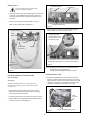
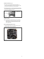
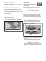
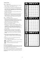
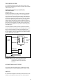
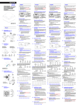
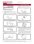
81-IN5219 WARRIOR 6
WS6
Product Instructions
REVISION DATE: 11-11-2010
TABLE OF CONTENTS
INSTALLATION PROCEDURE
Cable and Power Guidelines
Installation Preparation
Installation Procedure
Wiring
Optional Warrior Test Monitor Cable
Camera Bracket Setup
Camera Focusing
Camera Settings
Completion of Installation
Window Guard™ Replacement
NVT Instructions
Warranty Information
Service and Safeguard Information
Troubleshooting
1, 11
1
1
2
2
2
3
3
5
5
5
7
8
9
1. Using the security tool provided, loosen the (3) 10-32 security
fasteners and remove the face plate (Figure 1).
Figure 1
2. Place the back box into position and mark the four mounting
holes (Figure 2).
3. If you're using the top conduit knockout (Figure 2) REMOVE
THE CAMERA AND BRACKET TO PREVENT DAMAGE.
If using one of the side conduit knockouts it's not necessary to
remove the camera and bracket; however, use caution.
Top conduit knockout behind camera CAMERA MUST BE
REMOVED BEFORE USING
CABLE AND POWER GUIDELINES
(Detailed info on Page 11)
This chart shows the proper current needed for power supplies for
Warrior Series cameras. Use Class 2 Power only. Input voltage
must be between 12-28 VDC or 15-28 VAC.
VOLTAGE
CURRENT
POWER
12 VDC
350mA
4.2W
24 VAC
202mA
4.8W
Depending on the voltage being used, refer to one of the formulas
below to select the correct power supply for cameras connected
in parallel (positive to positive, negative to negative):
Total current for a 12 VDC system:
TOTAL CURRENT = (350mA x total number of cameras)
Total current for a 24 VAC system:
TOTAL CURRENT = (202mA x total number of cameras)
INSTALLATION PREPARATION
INSTALLATION PREPARATION
1. Choose an appropriate corner location. The WS6 can be
mounted at any height in a corner.
2. Complete all wire and conduit runs prior to installation of
the housing.
Mounting
Holes
Figure 2
Mounting Holes
4. Feed the wiring through the conduit knockout. A clamp
connector is included should you desire to use it. Install
the connector so that the nut is on the outside of the housing.
Be sure the hole in the wall is large enough to accommodate
the nut. Tighten the nut securely, making sure that the screw
heads on the connector are in an easy to reach position,
then feed the wiring through the clamp connector.
5. Mount the back box to the wall using appropriate hardware
(not provided).
NOTE: If the clamp connector was used, tighten the screws
at this time. Make sure enough wire is inside
the back box to complete the wiring process.
WIRING (Figure 3)
Terminal Connector
Use Class 2 Power only. Input voltage must be
between 12-28 VDC or 15-28 VAC.
Power Board
1. Connect the output of your Class 2 Power Supply to the terminal
connectors on the PC Board inside the housing. Refer to the
Troubleshooting section later in this instruction sheet for more
information.
2. Connect the incoming video cable to the BNC connector.
Test Monitor Cable plug
NOTE: For NVT Twisted Pair see Addendum 1.
Figure 4
3. Plug the test monitor cable into the power board (Figure 5).
Attach the BNC connector to your test monitor.
Terminal Connector
Power
Board
The plug for the Test
Monitor Cable is polarity
protected and can only
be inserted one way.
Positive
Connected to
the Camera
Negative
Test Monitor Cable (NOTE: Your cable may look different)
Connect to
incoming video
BNC
Figure 3
OPTIONAL WARRIOR TEST MONITOR CABLE
(Part # - WSTMC)
DESCRIPTION
The Warrior Test Monitor Cable is a tool that allows users to
view video from cameras via a small on-site monitor. It's quick
and easy to use.
Figure 5
NOTE: The following instructions are for camera bracket setup,
camera focusing, and camera set-up.
The final steps for installation follow these sections.
CAMERA BRACKET SETUP
8. To adjust the camera bracket, loosen the two thumb screws
(Figure 6). When the desired focus and location are achieved
tighten the thumb screws on the brackets in place using needle
nose pliers. Use Loctite™ or equivalent to secure the screws,
especially in installations where vibration is a concern.
Terminal Connector
1. Using the security tool provided, loosen the four security
fasteners and remove the housing top. NOTE: The housing
top is held to the base by a lanyard.
Video
Connector
2. Locate the power board on the inside of the housing. The Test
Monitor Cable plug is located beside the terminal block where
incoming power is connected (Figure 4).
Figure 6
-2-
Bracket adjustment thumb screws
CAMERA FOCUSING (Figure 7)
1. The camera is factory equipped with a 3.6mm fixed lens. A
2.5mm lens is also provided. To remove the 3.6mm lens, loosen
the set screw and unscrew the lens counter-clockwise.
2. Fine focusing of the lens: Loosen the set screw in the lens mount
and manually rotate the lens until a clear picture is achieved. Once
the focus is set, retighten the set screw.
Set screw
Fixed lens
Figure 7
CAMERA SETTINGS
NOTE: To determine which camera is used in your unit, locate the
serial number on the inside of the housing. Match the two
letter prefix with the corresponding instructions included
here for adjustments.
SERIAL NUMBERS BEGINNING WITH YK
FIXED AND FIXED VARI-FOCAL LENSES. There are no user
adjustable settings on these units (Figure 8).
BW Fixed and Vari-Focal
Figure 8
-3-
COMPLETION OF INSTALLATION
ADDENDUM 1
Reattach the front plate to the back box and tightly fasten the (3)
security screws using the security tool.
UNSHIELDED TWISTED PAIR
VIDEO WIRING
WINDOW GUARD™ PAINT SHIELD REPLACEMENT
Your Warrior 6 comes with a replaceable Window Guard™ paint
shield to protect the front plate window from vandalism. If vandalism
occurs (spray paint, scratches, etc.) you need only replace the shield,
not the entire window. Additional shields can be ordered. To replace
the shield, use the following directions.
1. Remove the face plate.
2. On the inside of the face plate, remove the (4) 6-32 nuts
holding the window in place (Figure 14).
3. Remove the damaged paint shield.
4. Place a new shield in front of the window. Reinstall the window,
making sure to securely tighten the (4) nuts. Reinstall the face
plate.
NOTE: The customer must purchase the Video Transceiver from
NVT. Part numbers are:
• NV-212A (500 ft.)
* NV-213A or NV-213A-M (1000 ft.)
• NV-652R, NV-862R, or NV-1662R (3000 ft.)
The cameras included in the Warrior series are able to transmit video
signals to NVT receivers via unshielded twisted pair cable. You must
purchase the receiver separately. Instructions for connecting the
receiver end of the unshielded twisted pair cable will be included
with the NVT receiver. Following are instructions for connecting the
unshielded twisted pair cable to the PC board inside your Warrior
housing. See the TROUBLESHOOTING section in the back of these
instructions if you experience any problems.
1. Connect the unshielded twisted pair cable to the positive and
negative screw terminals on the Warrior PC board (Figure 15).
Window
Video Negative (-)
Video Positive (+)
Window Guard™
Paint Shield
Figure 14
Figure 15
PC Board
2. Connect the other end of the unshielded twisted pair cable to the
NVT receiver.
CAUTION: The unshielded twisted pair video signal is polarity
dependent. The positive video terminal on the
Warrior PC board MUST be connected to
the positive terminal on the NVT receiver, and
negative MUST be connected to negative.
3. When using unshielded twisted pair cable you DO NOT need the
BNC connector. Be sure that there is no video connection other
than the unshielded twisted pair cable.
-4-
Wiring Notes
Cable
Distance
Wire — What to DO
250 ft
1.DO use point-to-point Unshielded Twisted Pair wire, gauge 24 or
thicker, stranded or solid, Category 2, 3, 4, or 5.
300 ft
2.The video signal may co-exist in the same wire bundle as other
video, telephone, data, control signals, or low-voltage power. It
is also OK to run NVT video signals in or near electromagnetic
fields (in accordance with National Electrical Code, local, or other
local safety requirements).
600 ft
400 ft
500 ft
3.DO measure the wire distance. Use only transceivers that are
designed for that distance.
800 ft
1000 ft
1250 ft
1500 ft
1750 ft
2000 ft
2500 ft
3000 ft
3500 ft
4.DO make sure the pair of wires carrying the video signal is sent
as a twisted pair (e.g. the blue-white/white-blue wires twisted
together as a pair), not a “split-pair” (e.g. blue-white conductor,
part of one pair/orange-white conductor, part of another pair).
4000 ft
5000 ft
6000 ft
8000 ft
Wire — What NOT to DO
Cable
Unshielded Twisted-Pair Wire Gauge (AWG)
18
3
4
5
6
8
10
13
16
19
23
26
32
39
45
52
65
78
104
W
W
W
W
W
W
W
W
W
W
W
W
W
W
W
W
W
W
19
4
5
6
8
10
13
16
20
24
28
32
40
48
56
64
80
95
127
W
W
W
W
W
W
W
W
W
W
W
W
W
W
W
W
W
W
20
5
6
8
10
12
16
20
25
30
35
40
49
59
69
79
99
119
158
W
W
W
W
W
W
W
W
W
W
W
W
W
W
W
W
W
W
22
8
10
13
16
19
25
32
40
48
55
63
79
95
111
127
158
190
253
W
W
W
W
W
W
W
W
W
W
W
W
W
W
W
W
W
W
24
13
16
21
26
31
42
52
65
78
91
104
131
157
183
209
261
313
418
W
W
W
W
W
W
W
W
W
W
W
W
W
W
W
W
W
W
Unshielded Twisted-Pair Wire Gauge (AWG)
18
19
20
22
24
75 m
3 W
4 W
5 W
8 W
13 W
100 m
4 W
5 W
6 W
10 W
17 W
125 m
5 W
7 W
8 W
13 W
21 W
150 m
6 W
8 W
10 W
16 W
26 W
2. Do NOT use un-twisted wire. It will reduce the NVT
product’s inherent interference immunity.
200 m
9 W
10 W
13 W
21 W
34 W
300 m
13 W
16 W
19 W
31 W
51 W
400 m
17 W
21 W
26 W
42 W
69 W
3.DO NOT allow your installation to have “bridge-taps”, loading
coils, talk-battery, or MOV type protectors. Bridge-taps are where
a twisted pair is connected to two twisted pairs (such as an
extension phone at home). Bridge-taps cause reflections as the
signal propagates, resulting in “ghosts” in the video image, and
are to be avoided.
500 m
21 W
26 W
32 W
52 W
86 W
600 m
26 W
31 W
39 W
62 W
103 W
750 m
32 W
39 W
49 W
78 W
129 W
900 m
38 W
47 W
58 W
94 W
154 W
1000 m
43 W
52 W
65 W
104 W
171 W
1200 m
51 W
63 W
78 W
125 W
206 W
1500 m
64 W
78 W
97 W
156 W
257 W
1800 m
77 W
94 W
117 W
187 W
309 W
2400 m
102 W
125 W
156 W
249 W
411 W
Distance
1. Do not use shielded twisted pair wire. It will
severely degrade the distance performance. Short runs may be
used with some signal degradation (for example elevator traveler
cables). Multi-pair wire with an overall shield is OK.
4.If the phone company is providing the cable runs between
buildings, make sure it’s “dry copper” i.e. it should have none
of the following: dial-tone, 48 volts, loading coils, bridge-taps,
switching, or long paths to the phone company’s central office
and back.
Cable
5.Due to near-end crosstalk, DO NOT send a transmit and a
receive signal in the same wire bundle. Exceptions: Less than
1,000 ft (300m), or Category 5 cable, up to 2,000 ft (600m) are
OK.
6.DO NOT send “Up-the-Coax” Pan/Tilt/Zoom signals through
active (amplified) NVT transceivers.
!
!
7.For safety, never put NVT signals in the same conduit as
high-voltage wiring.
8.WARNING — to reduce a risk of fire or electrical shock, do
not expose this product to rain or moisture.
Measure your wire distance
Note: All NVT quoted distance specifications include any coax in the
run. It is recommended that the wire distance be measured to ensure
that the capability of the NVT product is correct.
Wire resistance may be measured with an ohm-meter by shorting
the two conductors together at the far end, and measuring the loopresistance out and back. Compare your readings with the charts on
the next page.
-5-
Unshielded Twisted-Pair Wire Gauge (mm)
1.0
0.8
0.7
0.6
75 m
3
5
6
9
13 W
100 m
4
7
9
12
18 W
125 m
6
8
11
15
22 W
150 m
7
10
13
18
27 W
200 m
9
13
17
24
36 W
300 m
13
20
26
36
54 W
400 m
18
27
35
48
72 W
500 m
22
33
43
60
90 W
600 m
26
40
52
72
108 W
750 m
33
50
65
89
135 W
900 m
40
60
78
107
162 W
1000 m
44
66
86
119
179 W
1200 m
53
80
104
143
215 W
1500 m
66
100
130
179
269 W
1800 m
79
120
155
215
323 W
2400 m
106
159
207
286
431 W
Distance
0.5
IMPORTANT SAFEGUARDS
SAFETY PRECAUTIONS
1
Read these instructions.
2
Keep these instructions.
3
Heed all warnings
4
Follow all instructions.
5
Do not use this apparatus near water.
6
Clean only with damp cloth.
7
Do not block any of the ventilation openings. Install in accordance with the
CAUTION
RISK OF ELECTRIC SHOCK
DO NOT OPEN
manufacturers instructions.
8
Cable Runs- All cable runs must be within permissible distance.
9
Mounting - This unit must be properly and securely mounted to a supporting
structure capable of sustaining the weight of the unit.
Accordingly:
a. The installation should be made by a qualified installer.
b. The installation should be in compliance with local codes.
c. Care should be exercised to select suitable hardware to install the unit, taking into
account both the composition of the mounting surface and the weight of the
unit.
10 Do not install near any heat sources such as radiators, heat registers, stoves, or other
apparatus ( including amplifiers) that produce heat.
11 Do not defeat the safety purpose of the polarized or grounding-type plug. A
polarized plug has two blades with one wider than the other. A grounding type
plug has two blades and a third grounding prong. The wide blade or the third
prong are provided for your safety. When the provided plug does not fit into your
outlet, consult an electrician for replacement of the obsolete outlet.
12 Protect the power cord from being walked on or pinched particularly at plugs,
convenience receptacles, and the point where they exit from the apparatus.
13 Only use attachment/ accessories specified by the manufacturer.
14 Use only with a cart, stand, tripod, bracket, or table specified by the manufacturer,
or sold with the apparatus. When a cart is used, use caution when moving the cart/
apparatus combination to avoid injury from tip-over.
15 Unplug this apparatus during lighting storms or when unused for long periods of time.
16 Refer all servicing to qualified service personnel. Servicing is required when the
apparatus has been damaged in any way, such as power-supply cord or plug is
damaged, liquid has been spilled of objects have fallen into the apparatus, the
apparatus has been exposed to rain or moisture, does not operate normally, or
has been dropped.
Be sure to periodically examine the unit and the supporting structure to make sure that the
integrity of the installation is intact. Failure to comply with the foregoing could result in the
unit separating from the support structure and falling, with resultant damages or injury to
anyone or anything struck by the falling unit.
UNPACKING
Unpack carefully. Electronic components can be
damaged if improperly handled or dropped. If an item
appears to have been damaged in shipment, replace
it properly in its carton and notify the shipper.
Be sure to save:
1 The shipping carton and packaging material.
They are the safest material in which to make
future shipments of the equipment.
2 These Installation and Operating Instructions.
The lightning flash with an arrowhead
symbol, within an equilateral triangle, is
intended to alert the user to the presence
of non-insulated “dangerous voltage”
within the product’s enclosure that may be
of sufficient magnitude to constitute a risk
to persons.
Este símbolo se piensa para alertar al usuario a la
presencia del “voltaje peligroso no-aisIado” dentro del
recinto de los productos que puede ser un riesgo de
choque eléctrico.
Ce symbole est prévu pour alerter I’utilisateur à la
presence “de la tension dangereuse” non-isolée dans la
clôture de produits qui peut être un risque de choc
électrique.
Dieses Symbol soll den Benutzer zum Vorhandensein der
nicht-lsolier “Gefährdungsspannung” innerhalb der
Produkteinschließung alarmieren die eine Gefahr des
elektrischen Schlages sein kann.
Este símbolo é pretendido alertar o usuário à presença
“di tensão perigosa non-isolada” dentro do cerco dos
produtos que pode ser um risco de choque elétrico.
Questo simbolo è inteso per avvertire I’utente alla
presenza “di tensione pericolosa” non-isolata all’interno
della recinzione dei prodotti che può essere un rischio di
scossa elettrica.
The exclamation point within an equilateral
triangle is intended to alert the user to
presence of important operating and
maintenance (servicing) instructions in the
literature accompanying the appliance.
Este símbolo del punto del exclamation se piensa para
alertar al usuario a la presencia de instrucciones
importantes en la literatura que acompaña la
aplicación.
Ce symbole de point d’exclamation est prévu pour
alerter l’utilisateur à la presence des instructions
importantes dans la littérature accompagnant
l’appareil.
Dieses Ausruf Punktsymbol soll den Benutzer zum
Vorhandensein de wichtigen Anweisungen in der
Literatur alarmieren, die das Gerät begleitet.
Este símbolo do ponto do exclamation é pretendido
alertar o usuário à presença de instruções importantes
na literatura que acompanha o dispositivo.
SERVICE
If technical support or service is needed, contact us
at the following number:
TECHNICAL SUPPORT
AVAILABLE 24 HOURS
1 - 800 - 554 -1124
CAUTION: TO REDUCE THE RISK OF
ELECTRIC SHOCK, DO NOT REMOVE
COVER ( OR BACK). NO USER- SERVICEABLE PARTS INSIDE. REFER SEVICING TO
QUALIFIED SERVICE PERSONNEL.
-6-
Questo simbolo del punto del exclamaton è inteso per
avvertire l’utente alla presenza delle istruzioni importanti
nella letteratura che accompagna l'apparecchio.
WS6 Exploded Diagram and Replacement Parts List
1
2
3
5
4
Part Number
Description
1
RPWS6010
WARRIOR 6 FACE PLATE FASTENER KIT
2
RPWS6020
WARRIOR 6 FRONT PLATE ASSEMBLY
3
WS6PS
WARRIOR 6 REPLACEMENT PAINT SHIELD
4
RPWS6040
WARRIOR 6 REPLACEMENT WINDOW KIT
NTSC BOARD CAMERAS
5
RPWS6050
WARRIOR 6 STANDARD RES, BLACK & WHITE, FIXED
CAMERA KIT
RPWS6051
WARRIOR 6 STANDARD RES, COLOR, FIXED CAMERA KIT
RPWS6052
WARRIOR 6 HI-RES, COLOR, FIXED CAMERA KIT
PAL BOARD CAMERAS
6
RPWS6050P
WARRIOR 6 PAL STANDARD RES, BLACK & WHITE, FIXED
CAMERA KIT
RPWS6051P
WARRIOR 6 PAL STANDARD RES, COLOR, FIXED CAMERA KIT
RPWS6050P
WARRIOR 6 PAL HI-RES, COLOR, FIXED CAMERA KIT
RPWS6060
WARRIOR 6 CORNER PLATE
Not shown items
RPWS6070
WARRIOR 6 PACKET KIT
6
TROUBLESHOOTING
If you experience problems with the camera picture please check
these simple troubleshooting procedures for possible solutions before
calling technical support.
STATIONARY OR SCROLLING HORIZONTAL
LINES ON SCREEN
GROUND LOOPS
Generally a horizontal line on screen, whether moving or stationary,
means you have a ground loop problem. The video shield should
only be connected to ground through the monitor or other electronic
equipment that uses the video signal. Connecting the video shield to
ground at the camera will create a ground loop, which may interfere
with the video signal (See Figure A). This should not damage the
camera, but the video signal may become unusable. A ground loop
problem will cause a dark horizontal bar to slowly “scroll" through the
picture. To solve this problem, remove all ground connections from
the video connection EXCEPT for the ground at the terminating end
of the video signal.
The video termination should be a 75-ohm impedance, standard in
monitors and other video equipment. If the video signal goes to more
than one piece of equipment, a monitor and multiplexer input for
instance, insure that one and only one piece of equipment terminates
the video signal with 75 ohms; otherwise the image will be degraded
and may appear to be unusually dim.
Power A
Power Supply
Camera
Assembly
Primary
Power
Power B
Video Signal
(Ground Return)
Monitor
Video Shield
Figure A Ground Loop
IMPORTANT NOTE: If you have removed the ground loop and
the horizontal line still remains on screen
call Videolarm technical support for further
information.
AUTOMATIC BROWN OUT FEATURE
The camera includes an automatic brown out feature which is activated whenever the incoming voltage drops below 10 VAC or VDC.
LINE LOCK
All cameras are all shipped from the factory with the line lock function
disabled. If your application requires Line Lock contact Videolarm.
-8-
NVT TROUBLESHOOTING
If you are experiencing problems, attempt to simplify your setup. Test
each cable segment separately. For example, test the camera and
monitor together without the other equipment. Then add in the NVT
transceivers, back-to-back. Test each segment of a long cable-run
independently. Attempt to isolate the problem.
Below are problems that may be encountered. If the suggestions below
are not helpful, or the recommendations are not effective, please call
NVT’s customer support. NVT customer support can be reached 8:00
AM to 5:30 PM PST at (800) 959-9870 or at (+1) (650) 562-0600.
FAINT OR BLURRY PICTURE; LITTLE OR NO COLOR
Possible causes include:
1. Shielded twisted-pair cable. Verify that the wire is unshielded
twisted-pair cable. Multi-pair cable with an overall shield is OK.
2.Longer wire distance than expected. Be sure to include any coax
cable that’s part of this distance. Verify end-to-end connectivity
with an ohm meter. Measure the distance by disconnecting the
transceivers, shorting the far end, reading the loop’s resistance
at the near end. See above for ohm vs. distance ratings. If
necessary, replace transceivers with correct models specified for
this distance.
3.Incorrect distance equalization setting. Adjust the equalization
controls) with a mini screwdriver (NV-652R, NV-862R or the NV1662R). If the transmitter is an NV-653T, verify correct equalization
switch setting.
4.Poor connection at a punch-block, splice, or coax cable. Re-check
using the method described in #2 above, or use a wire test set.
5.Short between conductors of the twisted-pair. Use an ohm meter to
locate the short.
6.Transient protection devices employing metal-oxide varistors. Use
carbon blocks, gas-discharge tubes, or NVT transceivers with builtin protection.
7.Check the camera. Are the focus and iris set correctly? Verify with
portable monitor.
EXTREMELY FAINT PICTURE
Only faint shadows of the original picture are visible. One of the
twisted pair conductors is open or the wires are shorted together.
Check with an ohm meter.
OVER-SATURATED COLORS; HIGH CONTRAST GRAINY
PICTURE; TOO BRIGHT, TORN PICTURE
If the voltage is greater than 1/2 volt, use an amplified receiver,
such as the NV-652R, NV-862R, or NV-1662R.
Alternately, remove the ground at one end (usually at the camera
end). Be sure that floating the camera conforms to local/regional
and National Electrical Codes.
4.Check for crosstalk from a second video path. Disconnect all other
video sources. If the problem goes away, check for a split-pair or
un-twisted wire.
FAINT STRIPES GLIDING UP OR DOWN THE SCREEN
These are caused by crosstalk from a second video path, or with
ground-loops in installations employing passive models at both ends.
1.To identify, disconnect all other video signals temporarily. If the
interference goes away, check the wire to make sure the signal is
traveling through a twisted pair. Is two-way video being sent more
than 1,000 ft (300m) over Category 2 or 3 wire? If so, the send
and receive signals may need to go in separate jacketed cables,
or upgrade to Category 5 wire.
2.Next, check for ground loops. See #3 above.
NO POWER LIGHT ON THE NVT UNIT
Check the blue “power” LED on powered NVT units. If the light is not
on, the receiver is not getting power. Re-check the power source and
connections.
If the green LED is on but the power LED is off, check that the power
supply is floating. Grounding one side of the power input may cause
this condition.
NO GREEN LIGHT, NO VIDEO
The NV-652R, NV-862R or NV-1662R series receiver/hub is not
detecting a video signal. There is an open or shorted connection. Use
a multimeter to locate the fault.
GHOSTS
Faint shadows of the original signal shifted to the right. This is
caused by an impedance mismatch along the wire. Verify that the
monitor is terminated with 75 (not in “loop-through”.) Check that all
wire is unshielded twisted pair. The high-frequency wire impedance
should be 100. Check for bridge-taps (see below) either by inspecting
wiring closet connections, or, if available, using a “Time-Domain
Reflectometer” (T.D.R.), sometimes called a “cable tester”.
If the faint shadows are not copies of the original picture, but from the
picture of some other camera, check for crosstalk:
Is any portion of the wire un-twisted?
Adjust the distance equalization as necessary. Verify that the monitor
has a 75 termination, not in “loop-through”.
WON'T SYNC; WIDE, WHITE JAGGED AREAS
Are the signals from two cameras split between two pairs?
Is there a short between a conductor of one signal and a conductor
of another?
Looks like a scrambled Cable TV signal. Check polarity.
Bridge Tap
WON'T SYNC; TORN PICTURE
1.Make sure that you are using unshielded twisted pair wire.
13A
2.Check distance equalization settings.
NV-2
3.For installations with passive (non-amplified) transceivers at both
ends, check for ground loops. This may be done with an AC
Voltmeter, as shown below:
Camera
AC Voltmeter
-9-
NV-21
3A
Monitor
CABLE AND POWER GUIDELINES
This chart shows the proper current needed for power supplies for Warrior Series cameras. Use Class 2 Power only. Input voltage must be
between 12-28 VDC or 15-28 VAC
VOLTAGE
CURRENT
POWER
12 VDC
350mA
4.2W
24 VAC
202mA
4.8W
Depending on the voltage being used, refer to one of the formulas below to select the correct power supply for cameras connected in parallel
(positive to positive, negative to negative):
Total current for a 12 VDC system:
TOTAL CURRENT = (350mA x total number of cameras) Example: 350mA x 5 total cameras = 1750mA
Total current for a 24 VAC system:
TOTAL CURRENT = (202mA x total number of cameras) Example: 202mA x 5 total cameras = 1010mA
NOTE: If you're using a 12 VDC power supply and experience problems check the voltage at the camera's power input. This voltage should
not
be less than 11 VDC. If you're measuring less than 11 VDC you'll need to use a power supply with a higher current rating.
Power Supply Cable Maximum Length (feet/meters)
Total Load
Power Supply
24 AWG
22 AWG
18 AWG
16 AWG
4.2W
12 VDC
55/16
88/26
223/67
355/108
4.8W
24 VAC
867/264
1380/420
3488/1063
5547/1690
NOTE: The above table is based on a "worst-case" power supply. Using a regulated or switching power supply can increase your cable
distance. A CSA/UL listed Class 2 power supply must be used. Videolarm recommends its PS12 12 VDC 1000mA power supply for
12 VDC appl,ications
Video Cable Maximum Length (feet/meters)
Cable Type
RG-59
RG-6
RG-11
Wire Gauge
23 AWG*
18 AWG*
16 AWG*
Max. Length
750/229
1500/457
1800/549
* Copper clad steel core, 95% braided shield
Maximum Length (feet/meters)
AWG
250/76
500/152
1000/305
1500/457
2000/610
18
20
3Ω
6Ω
13Ω
19Ω
26Ω
40Ω
5Ω
10Ω
20Ω
30Ω
40Ω
59Ω
22
8Ω
17Ω
33Ω
48Ω
66Ω
99Ω
24
13Ω
26Ω
52Ω
78Ω
108Ω
163Ω
- 10 -
3000/914
LIMITED WARRANTY FOR VIDEOLARM INC. PRODUCTS
VIDEOLARM INC. warrants this Product to be free from defects in material or workmanship,as follows:
PRODUCTCATEGORY
PARTS
LABOR
All Enclosures and Electronics
Five (5) Years
Five (5) Years
Pan/Tilts
Three (3) Years **6 months if used in autoscan
Three (3) Years **6 months if used in autoscan
/tour operation
Poles/PoleEvators
Three (3) Years /tour operation
Three (3) Years
Warrior/Q-View/I.R. Illuminators
Five (5) Years
Five (5) Years
Five (5) Years
SView Series
Five (5) Years **6 months if used in autoscan
**6 months if used in autoscan
/tour operation
/tour operation
Controllers
Five (5) Years
Five (5) Years
Power Supplies
Five (5) Years
Five (5) Years
Accessory Brackets
Five (5) Years
Five (5) Years
During the labor warranty period, to repair the Product, Purchaser will either return the defective product, freight prepaid, or deliver it to Videolarm Inc.
an equal degree of protection with a
Decatur GA. The Product to be repaired is to be returned in either its original carton or a similar package
RMA # (Return Materials Authorization number) displayed on the outer box or packing slip. To obtain a RMA# you must contact our Technical Support
Team at 800.554.1124, extension 101. Videolarm will return the repaired Product freight prepaid to Purchaser. Videolarm is not obligated to provide
Purchaser with a substitute unit during the warranty period or at any time. After the applicable warranty period, Purchaser must pay all labor and/or
parts charges.
The limited warranty stated in these product instructions is subject to all of the following terms and conditions:
TERMS AND CONDITIONS
1. NOTIFICATIONOF CLAIMS: WARRANTYSERVICE: If Purchaser believes that the Product is defective in material or workmanship, then written notice
with an explanation of the claim shall be given promptly by Purchaser to Videolarm but all claims for warranty service must be made within the
warranty period. If after investigation Videolarm determines that the reported problem was not covered by the warranty, Purchaser shall pay Videolarm
for the cost of investigating the problem at its then prevailing per incident billable rate. No repair or replacement of any Product or part thereof shall
extend the warranty period as to the entire Product. The
warranty on the repaired part only shall be in
for a period of ninety (90) days
following the repair or replacement of that part or the remaining period of the Product parts warranty, whichever is greater.
2. EXCLUSIVE REMEDY: ACCEPTANCE:Purchaser’s exclusive remedy and Videolarm’s sole obligation is to supply (or pay for) all labor necessary to repair
any Product found to be defective within the warranty period and to supply, at no extra charge, new or rebuilt replacements for defective parts.
3. EXCEPTIONS TO LIMITED WARRANTY: Videolarm shall have no liability or obligation to Purchaser with respect to any Product requiring service
during the warranty period which is subjected to any of the following: abuse, improper use: negligence, accident, lightning damage or other acts
of God (i.e., hurricanes, earthquakes),
failure of the end-user to follow the directions outlined in the product instructions, failure of the
end-user to follow the maintenance procedures recommended by the International Security Industry Organization, written in product instructions,
for regular
or recommended in the service manual for the Product. Furthermore, Videolarm shall have no liability where a schedule is
replacement or maintenance or cleaning of certain parts (based on usage) and the end-user has failed to follow such schedule; attempted repair by
personnel; operation of the Product outside of the published environmental and electrical parameters, or if such Product’s original
(trademark, serial number) markings have been defaced, altered, or removed. Videolarm excludes from warranty coverage Products sold
AS IS and/or WITH ALL FAULTS and excludes used Products which have not been sold by Videolarm to the Purchaser. All software and accompanying
documentation furnished with, or as part of the Product is furnished “AS IS” (i.e., without any warranty of any kind), except where expressly provided
otherwise in any documentation or license agreement furnished with the Product.
4. PROOF OF PURCHASE: The Purchaser’s dated bill of sale must be retained as evidence of the date of purchase and to establish warranty eligibility.
DISCLAIMEROF WARRANTY
EXCEPT FOR THE FOREGOING WARRANTIES, VIDEOLARM HEREBY DISCLAIMS AND EXCLUDES ALL OTHER WARRANTIES, EXPRESS OR IMPLIED,
INCLUDING, BUT NOT LIMITED TO ANY AND/OR ALL IMPLIED WARRANTIES OF MERCHANTABILITY, FITNESS FOR A PARTICULAR PURPOSE AND/OR ANY WARRANTY WITH
REGARD TO ANY CLAIM OF INFRINGEMENT THAT MAY BE PROVIDED IN SECTION 2-312(3) OF THE UNIFORM COMMERCIAL CODE AND/OR IN ANY OTHER COMPARABLE
STATE STATUTE. VIDEOLARM HEREBY DISCLAIMS ANY REPRESENTATIONS OR WARRANTY THAT THE PRODUCT IS COMPATIBLE WITH ANY COMBINATION OF NON-VIDEOLARM
PRODUCTS OR NON-VIDEOLARM RECOMMENDED PRODUCTS PURCHASER CHOOSES TO CONNECT TO PRODUCT.
LIMITATION OF LIABILITY
THE LIABILITY OF VIDEOLARM, IF ANY, AND PURCHASER’S SOLE AND EXCLUSIVE REMEDY FOR DAMAGES FOR ANY CLAIM OF ANY KIND
WHATSOEVER, REGARDLESS OF THE LEGAL THEORY AND WHETHER ARISING IN TORT OR CONTRACT, SHALL NOT BE GREATER THAN THE ACTUAL PURCHASE PRICE OF THE
PRODUCT WITH RESPECT TO WHICH SUCH CLAIM IS MADE. IN NO EVENT SHALL VIDEOLARM BE LIABLE TO PURCHASER FOR ANY SPECIAL, INDIRECT, INCIDENTAL, OR
CONSEQUENTIAL DAMAGES OF ANY KIND INCLUDING, BUT NOT LIMITED TO, COMPENSATION, REIMBURSEMENT OR DAMAGES ON ACCOUNT OF THE LOSS OF PRESENT
OR PROSPECTIVE PROFITS OR FOR ANY OTHER REASON WHATSOEVER.
- 11 -
Product Registration/Warranty
Thank you for choosing Videolarm. We value your patronage and are solely committed to providing you
with only the highest quality products available with unmatched customer service levels that are secondto-none in the security industry.
Should a problem arise, rest assure that Videolarm stands behind its products
by offering some of the most impressive warranty plans available: 3 Years
on all Housings, Poles, Power Supplies, and Accessories and 5 Years on
all camera systems (SView, QView, Warriors), and InfraRed Illuminators.
Register Your Products
Option 1: Online Option 2: Mail-In
Take a few moments and validate your purchase with our Online Product Registration Form
www.videolarm.com/productregistration.jsp
at
or complete and mail-in the bottom portion of this flyer.
Register your recent Videolarm purchases and benefit from the following:
• Simple and Trouble-Free RMA process
• Added into customer database to receive product updates / news
• Eliminate the need to archive original purchase documents:
Receipts, Purchase Orders, etc…
Cut at the dotted Line
Main Contact Info
Place in envelope, affix stamp and mail to:
Videolarm ATTN: Warranty
2525 Park Central Ave.
Decatur, GA 30035
First Name:
Last Name:
Professional Title:
Company:
Address 1:
Address 2:
City:
State / Province/Country:
Zip / Postal Code:
Phone Number:
Product Information E-mail Address:
Please Circle One:
Name & Location of Company / Store where Purchased:
(City, State, Country)
Videolarm Product ID
Product Description
Serial #
(Available only for Camera Systems, IR Illuminators, Wireless Devices)
PO#
- 12 -
Business
Personal