1
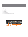
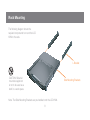
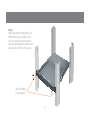
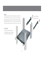
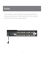
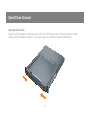
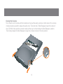
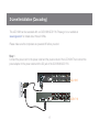
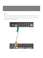
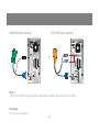
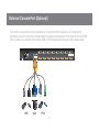
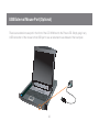
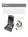
Installation Guide 8/16-Port 17” LCD Combo KVM Switch 1 GCL1808/GCL1816 PART NO. M1123/M1124 ©2009 IOGEAR. All Rights Reserved. Part No. M1123/M1124 IOGEAR, the IOGEAR logo, MiniView®, VSE are trademarks or registered trademarks of IOGEAR. Microsoft and Windows are registered trademarks of Microsoft Corporation. IBM is a registered trademark of International Business Machines, Inc. Macintosh, G3/G4 and iMac are registered trademarks of Apple Computer, Inc. IOGEAR makes no warranty of any kind with regards to the information presented in this document. All information furnished here is for informational purposes only and is subject to change without notice. IOGEAR, Inc. assumes no responsibility for any inaccuracies or errors that may appear in this document. 2 Table of Contents Package Contents System Requirements Overview Rack Mounting Grounding Open/Close Console Single Level Installation 2-Level Installation (Cascading) External Console Port (Optional) USB External Mouse Port (Optional) USB Sharing Port LCD Configuration LCD Adjustment Setting Reset Button LED Indication Keyboard Function Keys Port Switching On-screen Display (OSD) Operation Hotkey Setting Mode (HSM) Mac Keyboard Emulation Sun Keyboard Emulation Factory Default Settings Firmware Upgrade Upgrade Fail Restore Factory Default Settings Safety Instructions Specifications Federal Communications Commission (FCC) Statement CE Statement SJ/T 11364-2006 Limited Warranty Contact 4 5 6 8 11 12 14 17 21 22 23 24 25 26 27 28 29 3 30 57 60 61 62 63 67 68 70 74 75 76 77 78 79 Package Contents - 1 x 8/16-Port LCD KVM - 1 x PS/2 KVM Cable - 1 x USB KVM Cable - 1 x Console Cable - 1 x Firmware Upgrade Cable - 1 x Rack Mount Kit (Long and Short L Brackets) - 1 x Grounding Wire - 1 x Power Cord - 1 x Installation Guide - 1 x Warranty Card 4 System Requirements Computers • VGA, SVGA, or MultiSync video graphics card with an HDB-15 port • PS/2 mouse and keyboard ports (6-pin mini DIN) or 1 USB port 5 Overview Slide Release Handle Bar LCD Display LCD Power Button LCD Controls Port LEDs (8 for GCL1808 and 16 for GCL1816) 7. Keyboard 8. Touchpad 9. External USB Mouse Port 10.Power LED 11.Master/Slave Port Switches 12.Num Lock/Caps Lock/Scroll Lock LED 13.Reset Button 14.Firmware Upgrade Recovery Switch 15.Firmware Upgrade Port 16.USB Sharing Port 1 1. 2. 3. 4. 5. 6. 2 3 4 16 5 15 6 7 14 8 13 12 11 Front view 6 9 10 1. 2. 3. 4. 5. Grounding Terminal Power Socket Power Switch External Console Port CPU Ports (8 for GCL1808 and 16 for GCL1816) 16 15 14 13 12 11 10 8 7 6 5 4 3 2 9 PS/2-USB CONSOLE 1 2 3 5 4 Back view 7 1 CPU Rack Mounting The following diagram shows the required components to mount the LCD KVM to the rack. L Bracket CAUTION: Slide/rail mounted equipment is not to be used as a shelf or a work space. Side Mounting Brackets Note: The Slide Mounting Brackets are pre-installed onto the LCD KVM. 8 Step 1 While one person holding the LCD KVM in the proper position in the rack, the second person can lock the screws loosely through the front bracket onto the front of the rack. M4 x 6 Phillips Head Screws 9 Step 2 While the person continue holding the position of the LCD KVM, the second person can slide the L brackets from the back of the rack into the Slide Mounting Brackets. Then, you can lock the screws through the rear bracket onto the back of the rack. M4 x 6 Phillips Head Screws Final Step After the rear brackets are completely secured, tighten the front brackets’ screws. 10 Grounding To prevent damaging your equipment, it is important that all devices are properly grounded. Use the included grounding wire to ground the LCD KVM by connecting one end of the wire to the grounding terminal, and the other end of the wire to a suitable grounded object. 16 15 14 13 12 11 10 9 PS/2-USB 8 7 6 CONSOLE 11 5 4 3 2 1 CPU Open/Close Console Opening the Console Slide the 2 Slide Releases toward the center of the LCD KVM, then pull the console module out while holding the Slide Releases’ position. Then simply open the console by raising the handle bar. 12 Closing the Console First, close the LCD module with the handle bar, then pull the safety catches on both sides of the console module towards yourself to release the safety lock. Then slide the 2 Slide Releases toward the center of the LCD KVM, then push the console module all the way in while holding the Slide Releases’ position. Then simply release the Slide Releases to keep the console module in the lock position. 13 Single Level Installation Please make sure the computers are powered off before you start. Step 1 Connect the power cord to the power outlet and the power socket of the LCD KVM. 16 15 14 13 12 11 10 8 7 6 5 4 3 2 9 PS/2-USB CONSOLE 14 1 CPU Step2 Connect a USB KVM Cable (with a green connector) or PS/2 KVM Cable (with a yellow connector) from the KVM switch to each of your computers 16 15 14 13 12 11 10 9 PS/2-USB 8 7 6 5 4 3 CONSOLE USB KVM Cable Connection or 15 PS/2 KVM Cable Connection 2 1 CPU Step 3 Turn on LCD KVM by using the power switch that’s located in the back of the LCD KVM. 16 15 14 13 12 11 10 9 PS/2-USB 8 7 6 CONSOLE Final Step Turn on your computers. 16 5 4 3 2 1 CPU 2-Level Installation (Cascading) This LCD KVM can be cascaded with our GCS1808/GCS1716. Please go to our website at www.iogear.com for details about those 2 KVMs. Please make sure the computers are powered off before you start. Step 1 Connect the power cord to the power outlet and the power socket of the LCD KVM. Then connect the power adapter to the power outlet and the DC jack of the GCS1808/GCS1716. 16 15 14 13 12 8 7 6 5 4 11 9 10 PS/2-USB GCL1816 3 CONSOLE CONSOLE 17 18 17 16 15 8 7 6 5 14 13 4 PS/2-USB 3 CPU 2 12 11 2 1 GCS1716 1 CPU Step 2 Connect the Cascade Cable between the back of the LCD KVM and a GCS1808/GCS1716. Connect the green connector to one of the CPU ports from the LCD KVM. Then, connect the yellow connector to the console port of the GCS1808/GCS1716. 16 15 14 13 12 11 10 8 7 6 5 4 3 2 9 PS/2-USB CPU 1 CONSOLE 1st Level 18 17 16 15 14 13 12 11 8 7 6 5 4 3 2 1 CONSOLE PS/2-USB CPU 2nd Level 18 Step 3 Connect a USB KVM Cable (with a green connector) or PS/2 KVM Cable (with a yellow connector) from the KVM switch to each of your computers. 18 17 16 15 14 13 12 11 8 7 6 5 4 3 2 1 CONSOLE PS/2-USB CPU 2nd Level 19 USB KVM Cable Connection PS/2 KVM Cable Connection or Step 4 Turn on LCD KVM by using the power switch that’s located in the back of the LCD KVM. Final Step Turn on your computers. 20 External Console Port (Optional) If you wish to use external monitor, keyboard or mouse rather then the built-in LCD, keyboard or touchpad, you can connect the console cable to the external console port in the back of the LCD KVM. Then, connect your external VGA monitor, USB or PS/2 keyboard and mouse to the console cable. 16 15 14 13 12 11 10 8 7 6 5 4 3 2 9 PS/2-USB CONSOLE USB VGA PS/2 21 1 CPU USB External Mouse Port (Optional) There is an external mouse port in the front of the LCD KVM next to the Power LED. Simply plug in any USB connection of the mouse to that USB port to use an external mouse instead of the touchpad. 22 USB Sharing Port The USB sharing port is located below the LCD display and next to the firmware upgrade port. This USB port allows you to share a USB device ONLY for the computers that are connected to the LCD KVM via USB KVM Cable (The green connector KVM cable). Also, the USB device can ONLY be shared between the computers that are physically connected to the same level of the LCD KVM. That means the 2nd level cascading computers cannot share this USB device if the USB device is connected to the LCD KVM (1st level). A USB printer or other USB devices such as a USB scanner, a USB flash drive, etc. 23 LCD Configuration There are four buttons for LCD configuration, the functions are as follow: Button Function Menu • If you are currently not in the LCD OSD (On Screen Display) Menu, press this Menu button will bring up the LCD OSD Menu. • If you are currently in the LCD OSD Menu, this button acts as an Enter button. | This button navigates up or right within the OSD Menu. During an adjustment, this button increases the value of the specific adjustment. | This button navigates left or down within the OSD Menu. During an adjustment, this button decreases the value of the specific adjustment. Exit • If you are currently not in the LCD OSD Menu, press this Exit button will perform an auto adjustment. • If you are currently in the LCD OSD Menu, press this Exit button to exit from the current menu and return to the previous menu. • If you are currently in the LCD OSD main menu, press this Exit button to exit from the OSD. 24 LCD Adjustment Setting There are ten functions in the LCD OSD Menu, and they are as follow: Setting Function Brightness This function adjusts the brightness of the LCD Contrast This function is to eliminate pixel jitters or horizontal line noise Phase This function is to eliminate vertical banding Clock If a port has been given a name, its name appears in this column. H-Position This function is to adjust the position of the LCD panel horizontally V-Position This function is to adjust the position of the LCD panel vertically Color Temperature This function is to adjust the color quality of the LCD. The warmth value and color balance can be adjusted by this function. The Adjust Color selection has a submenu that lets you fine tune the RGB values. Language This function is to select the OSD Menu display language OSD Duration This function is to set the amount of time for the LCD. If there is no input for this amount of time, LCD display will turn off. Reset This function turns all LCD settings back to factory default settings 25 Reset Button Use a paper clip or any kind of small object to press the reset button, you will then hear a beep sound which indicates that it will perform a system reset on the LCD KVM. RESET RESET 26 LED Indication LED Description No LED No computer is connected to the specific port or the computer is connected to the specific port but it is not powered on Orange The specific port has a computer connected and it is powered on 27 Keyboard Function Keys There are 6 sets of Keyboard Function Keys on the built-in keyboard and they are as follow. Simply Hold the [Fn] key then press the function key and release the [Fn] key to trigger the specific function. Function Description Mute key Volume Down key Volume Up key Trigger Computer Sleep Mode Home END Home key End key 28 Port Switching Port Switching via Port Switches If you wish to switch to a port that’s on the 1st level, simply press the up or down button to select the Master Port ID If you wish to switch to a port that is on the 2nd level, first, press the up or down button to select Master port ID for the port on the 1st level that is connected to the desire 2nd level’s port. Then select the desire port that’s connected to the computer on the 2nd level by pressing up or down button to select the Slave Port ID Port Switching via On-Screen DIsplay (OSD) Please refer to OSD Operation section. Port Switching via Hotkey Please refer to Hotkey Setting Mode (HSM) section. 29 On-screen Display (OSD) Operation Trigger OSD Simply press [Scroll Lock] [Scroll Lock] rapidly. OSD Main Screen When you invoke the OSD, a screen similar to the one below appears: Note: This hotkey sequence can be changed to [Ctrl] [Ctrl]. Please refer to Hotkey Setting Mode (HSM) section. or Press [KVM OSD] Button that is located on the left bottom corner of the built-in keyboard. OSD Login By default, the Login and Password are blanks, so simply press [Enter] [Enter] to login. If you have set a user name and password on the KVM, simply enter them and press enter to login. 30 Notes: 1. The diagram depicts the administrator’s main screen. The user main screen does not show the F4 and F6 functions, since these are reserved for the administrator and can’t be accessed by users. 2. The OSD always starts in list view, with the highlight bar at the same position it was in the last time it was closed. 3. Only the ports that have been set accessible by the administrator for the current logged in user are visible. 4. If there is a next to the monitor icon, which means that port is attached to another KVM (Cascading). Click on a switch number, or move the highlight bar to it then press the right arrow key to expand the list. Similarly, to collapse a switch’s port list, click on the switch number, or move the highlight bar to it then press the left arrow key to collapse the list. 31 OSD Main Screen Headings Heading Description PN This column lists the port ID numbers for all the KVM ports on the installation. The simplest method to access a particular computer is move the highlight bar to it then press Enter. QV QV If a port is selected for quick view scanning an arrowhead shows in this column. ☼ The computers that are powered on and are online will a sun symbol in this column to indicate so Name If a port has been given a name, its name appears in this column. 32 OSD Navigation • To dismiss the menu, and deactivate OSD, click the X in the upper right corner of the OSD window; or press [Esc]. • To log out, click F8 at the top of the main screen, or press [F8]. • To move up or down through the list one line at a time, click the up and down triangle symbols () or use the up and down arrow keys on the keyboard. If there are more list entries than what appears on the main screen, the screen will scroll down. • To move up or down through the list one screen at a time, click the up and down arrow symbols (), or use the [PgUp] and [PgDn] keys. If there are more list entries than what appears on the main screen, the screen will scroll. • To activate a port, double-click it, or move the highlight bar to it then press [Enter]. • After executing any action, you automatically go back to the menu one level above. OSD Function There are eight options showing on top of the OSD screen. Simply click the function key on the top of the screen or press the specific function key on the keyboard on access the specific function. 33 F1: GOTO F1: GOTO This function is to let you switch to a specific port via port ID or port’s name. Enter [1] to choose from Port Name and [2] to choose from Port Number in the yellow box locating in the bottom of the pink bar. If [1] was chosen, then type in the port’s name that you want to go to and then press [Enter]. You can also move the red highlight bar to the specific port that you want to go to and press [Enter]. 34 F2: LIST If [2] was chosen then you can go to a specific port by entering the port ID. You can also move the red highlight bar to the specific port that you want to go to and press [Enter]. F2: LIST This function allows you to choose a way that you wish to list the ports in the OSD display on the main screen. Simply move the red highlight bar to the option that you wish to choose and press [Enter]. You will see the hand symbol will be pointing at the option that you chose, then simply press [Esc] to exit the function. 35 Function Description All List out all ports that the administrator has set as accessible for the current logged in user Quick View List out only the ports that have been set as quick view ports Powered ON List out only the ports that have been powered on Quick View + Powered ON List out only the ports that have been set as quick view ports and they have been powered on 36 F3: SET OSD Hotkey This function allows you to switch the way to trigger the hotkey between [Scroll Lock] [Scroll Lock] and [Ctrl] [Ctrl]. Simply move the red highlight bar to the hotkey setting that you would like to choose and press [Enter]. Then press [Esc] to exit from this function. F3: SET There are 11 different settings within the SET section, which they are as follow: OSD Hotkey Port ID Display Position Port ID Display Duration Port ID Display Mode Scan Duration Scan-Skip Mode Screen Blanker Hotkey Command Mode Hotkey OSD Language Touchpad 37 Port ID Display Position This function allows you to change the position of the port ID that’s showing on the screen as the image below. Simply change the position by using the up, down, left and right arrows to adjust to the place that you want the port ID to show in the future and press [Enter]. Port ID Display Duration This function allows you to change the port ID display duration between 3 seconds and off. Simply move the red highlight bar to the option that you would like to choose and press [Enter]. Then, press [Esc] to exit this function. 38 Scan Duration This function allows you to set the autoscan time interval between 0 second to 255 seconds (5 second is set by default). Simply enter the number between 0-225 and press [Enter]. Port ID Display Mode This function allow you to choose the way you want to show the ports in the OSD main screen – port number only, port name only or both. Simply move the red highlight bar to the option that you like to use and press [Enter]. Then, press [Esc] to exit from this function. 39 Scan-Skip Mode This function allows you to set the behavior in autoscan mode. Simply move the red highlight bar to the behavior you want and press [Enter]. Then, press [Esc] to exit from this function. Function Description All Scan all ports that the administrator has set as accessible for the current logged in user Quick View Scan only the ports that have been set as quick view ports (This option will only show up for administrator account) Powered ON Scan only the ports that have been powered on Quick View + Powered ON Scan only the ports that have been set as quick view ports and they have been powered on 40 Screen Blanker This function allows you to set the time interval to have the KVM goes to a black screen. Simply enter the number between 0 to 30 and press [Enter]; then, press [Esc] to exit from this function. Hotkey Command Mode This function allows you to enable or disable the hotkey commands. Simply press Y for yes and N for no. Then, press [Esc] to exit from this function. 41 OSD Language This function allows you to choose the OSD language between English, Deutsch, Japanese, Simplified Chinese and Traditional Chinese. Simply move the red high light bar to the language that youwish to choose and press [Enter]. Then, press [Esc] to exit from this function. Hotkey This function allows you to set the hotkey sequence that you wish to use to trigger hotkeys commands. Simply move the red high light bar to choose the sequence that you wish to use and press [Enter]. Then, press [Esc] to exit from this function. 42 Touchpad This function allows you to enable/disable the touchpad. It will ask if you want to enable the touchpad or disable the touchpad depending on the current status of it. Simply press Y for yes and N for no. 43 F4: ADM F4: ADM This function will only be shown if you have login as Administrator. There are 12 different functions within the ADM section, which they are as follow: Set User Login This function allows you to setup the login name and password for the users accounts. There are 5 user accounts in the system – Administrator, User1, User2, User3 and User4. Move the red high light bar to the user account that you wish to setup and press [Enter]. Set User Login Set Accessible Ports Set Logout Timeout Edit Port Names Restore Default Values Clear The Name List Activate Beeper Set Quick View Ports Set Operating System Firmware Upgrade Keyboard Language Set Console Mode Keyboard Language 44 Then simply type in the user name and password. Then, enter the password again for confirmation then press [Enter]. (We have used the administrator account as an example.) Once the user name and password are set correctly, you will see the message in the bottom of the screen indicating the setup is ok. Then simply press [Esc] to exit from the function. 45 Set Accessible Ports This function allows you to setup the access on each port for each user. Use [Spacebar] to cycle through all the entries and press [Enter] to complete the setup. Then, press [Esc] to exit from the function. Function Description F (Full) User has full access on the specific port V (View) User can only view the port with no access for the specific port (Blank) User cannot view nor access for the specific port 46 Set Logout Timeout This function allows you to set a time that the KVM will automatically logout after being idle for a certain period of time. Move the red highlight bar to this function and press [Enter]. Then enter a number from 0-180 (in terms of minutes) as the time interval and press [Enter]. Edit Port Names This function allows you to customize a name on each port of the KVM. Simply move the red highlight bar to the port that you wish to customize a name and press [Enter]. 47 Restore Default Values This function allows you to restore all settings into factory default settings. Move the red highlight bar to Restore Default Values and press [Enter]. Then type Y to proceed restoring or N to cancel the restore. Enter the port name that you wish to show in OSD for that specific port and press [Enter] to complete the editing. Then, press [Esc] to exit from this function. 48 Activate Beeper This function allows you to enable or disable the beeper sound while switching port. Move the red highlight bar to Activate Beeper and press [Enter]. Then type Y to activate or N to deactivate. Clear The Name List This function allows you to clear up all the port names to blanks. Move the red highlight bar to Clear The Name List and press [Enter]. Then type Y to proceed clearing or N to keep the name list. 49 Set Quick View Ports This function allows you to set the desire ports as Quick View Ports. If a port is selected as a Quick View Port, an icon will show in the QV column of the OSD main screen. Simply more the red highlight bar to the desire port and press [Spacebar] to select the port as a Quick View Port. 50 Set Operating System This function allows you to define what kind of operating system is being used in each port. Simply move the red highlight bar to the desire port and press [Spacebar] to cycle through the options between WIN, MAC, SUN or OTHER. Note: The keyboard Operating platform will changed accordingly depending what you have chosen in this function. For example, if you have chosen Mac in Port 1 as the image is shown, the keyboard will change Mac keyboard emulation mode. Please see Hotkey Setting Mode (HSM) and Mac/Sun Keyboard Emulation sections to see the details. 51 Firmware Upgrade This function allows you to have the KVM activates the firmware upgrade mode so that you can perform a firmware upgrade to the KVM. If you would like to do a firmware upgrade, connect the firmware cable between the computer and KVM, then type Y to proceed with the firmware upgrade; otherwise, type N to cancel. After you type Y, you will see the below screen. The KVM is now in firmware upgrade mode. Please see Firmware Upgrade section for details about how to perform a firmware upgrade. 52 Set Console Mode This function allows you to selects which console to be enabled. [0] is to enable both Internal Console and optional External Console, [1] is to enable Internal Console ONLY and [2] is to enable External Console ONLY. The default is [0], use [Spacebar] to cycle to the option that you wish to select then press [Esc] to exit the function*. Keyboard Language This function allows you to choose the keyboard language of your console keyboard. Auto is chosen by default; if you want to change the language, simply move the red highlight bar to the desire keyboard language that you wish to change to and then press [Enter]. 53 *Please note that the function will not take affect until you have logout from the OSD. F5: SKP F5: SKP This function allows you to trigger Skip Mode. Simply press [F5] to activate skip mode. When you see a left and right arrow next to the port number as the image below, you can press the arrow keys to skip to different ports. (Skip Mode’s behavior depends on the setup that you chose in Scan-Skip Mode, please to F3 – SET for more detail about Scan-Skip Mode) Function Description [←] Switch to the last accessible port [→] Switch to the next accessible port [↑] Switch to the last accessible port* Note: If you have cascaded your KVM, it will switch to the last accessible port from level 2 of the last port from level 1. [↓] Switch to the next accessible port* Note: If you have cascaded your KVM, it will switch to the next accessible port from level 2 of the next port from level 1. 54 F6: BRC / F7: SCAN F6: BRC This function will only be shown if you have login as Administrator. Simply press [F6] to trigger Broadcast (BRC) Mode, then you will see a speaker symbol next to the port number. When BRC is activated, your command that you send from the console will be sent to all available computers – the computers that are listed in the OSD main screen, please go to F2 – LIST section for details. During BRC Mode, console mouse will not function normally. Simply press [F6] again to turn BRC Mode off. F7: SCAN This function allows you to autoscan all the available ports. (This autoscan behavior depends on the Scan-Skip Mode and Scan Duration.) Please go to F3 – SET section for details. Simply press [F7] to trigger Autoscan Mode, then you will see a [S] next to the port ID number on the screen. When the Autoscan Mode is activated, the console will not function normally until you exit from Autoscan Mode. During Autoscan Mode, you can press [P] or left-click on your mouse once to pause at a specific port. When you are done pausing, simply press any key from the keyboard or left-click once on your mouse to resume. When you are done auto-scanning, simply press [Spacebar] or [Esc] to exit from Autoscan Mode. 55 F8: LOUT F8: LOUT This function allows you to logout of the OSD. So, when another person is trying to access this from the console, he would have to login again. Simply Press Y to proceed the logout and N to cancel. 56 Hotkey Setting Mode (HSM) Function Description 1. Press and hold [Num Lock] 2. Press and release [-] 3. Release [Num Lock] or Press [KVM Hotkey] Button that is located on the left bottom corner of the built-in keyboard. Invoking hotkey setting mode Invoke HSM, then press [h] Change the HSM invocation keys from [Num Lock] to [Ctrl] and from [-] to [F12] Invoke HSM, then press [t] Switch port switching hotkey sequence between [Scroll Lock] [Scroll Lock] and [Ctrl] [Ctrl] Invoke HSM, then press [F1] Set keyboard operating platform to PC compatible Invoke HSM, then press [F2] Set keyboard operating platform to Mac compatible Invoke HSM, then press [F3] Set keyboard operating platform to Sun compatible Note: To exit HSM manually, press Esc or spacebar. 57 Invoke HSM, then press [F5] Perform keyboard / Mouse reset on the port that has KVM focus. Note: You can also press and hold Port 1 and Port 2 front panel push button to perform keyboard / mouse reset. Invoke HSM, then press [←] Invokes Skip mode and skips from the current port to the first accessible port previous to it Invoke HSM, then press [→] Invokes Skip mode and skips from the current port to the next accessible port Invoke HSM, then press [↑] Switch to the last accessible port* Note: If you have cascaded your KVM, it will switch to the last accessible port from level 2 of the last port from level 1. Invoke HSM, then press [↓] Switch to the next accessible port* Note: If you have cascaded your KVM, it will switch to the next accessible port from level 2 of the next port from level 1. 58 Invoke HSM, then press [b] Toggle hotkey beepers on or off Invoke HSM, then press [X*] [Y*] [Enter] Switches KVM focus to the computer that is connected to Port X in the 1st Level and Port Y in the 2nd Level Note: If you only have a single level installation, simply ignore the Y interval Invoke HSM, then press [r] [Enter] Restore default settings (Administrator ONLY) Invoke HSM, then press [a] [Enter] or Invoke HSM, then press [q] [Enter] Invoke Auto Scan Mode Note: Auto Scan can be paused and resume by pressing [p] or by a single left-click on the mouse *Note: X and Y are intervals from 1-8 (for GCL1808) and 1-16 (for GCL1816). When you enter, please make sure you enter each of them as a 2 digit number, for example, you would need to type 01 for port 1. 59 Mac Keyboard Emulation The PC compatible (101/104 key) keyboard can emulate the functions of the Mac keyboard. The emulation mappings are listed in the table below. PC Keyboard Mac Keyboard [Alt] Alt [Shift] Shift [Print Screen] F13 [Crtl] Ctrl [Scroll Lock] F14 = [Ctrl] [1] [Enter] Return [Ctrl] [2] [Backspace] Delete [Ctrl] [3] [Insert] Help [Ctrl] [4] [Ctrl] F15 *Note: When using key combinations, press and release the first key (Ctrl), then press and release the second key. 60 Sun Keyboard Emulation The PC compatible (101/104 key) keyboard can emulate the functions of the Sun keyboard. The emulation mappings are listed in the table below. Sun Keyboard [Ctrl] [F9] Find [Crtl] [t] Stop [Crtl] [F10] Cut [Crtl] [F2] Again [Crtl] [1] [Crtl] [F3] Props [Crtl] [2] [Crtl] [F4] Undo [Crtl] [3] [Crtl] [F5] Front [Crtl] [4] [Crtl] [F6] Copy [Crtl] [h] [Crtl] [F7] Open [Crtl] [F8] Paste PC Keyboard Help Compose *Note: When using key combinations, press and release the first key (Ctrl), then press and release the second key. 61 Factory Default Settings Function Default Settings OSD Hotkey [Scroll Lock] [Scroll Lock] Invoking HSM [Num Lock] [-] Auto Scan Duration 5 seconds Scan-Skip Mode All Screen Blanker Off Beeper On Keyboard Operating Platform PC Compatible Port ID Display Position Upper left corner Port ID Display Duration 3 seconds Port ID Display Mode Port Number + Port Name Accessible Ports F (Full) For all Users on all ports Auto-Logout Time Disabled 62 Firmware Upgrade Note: In order to perform a firmware upgrade, you need to use a set of computer that is not connected to the LCD KVM. Step 3 Go to www.iogear.com from the computer that performing the firmware upgrade to download the latest available firmware or the specific firmware that you wish to upgrade to. Step 1 Connect the provided firmware upgrade cable to the firmware upgrade port of the LCD KVM and the serial port of the computer that you will be using to perform the firmware upgrade. Step 4 Make sure all the computers that are connected to the KVM are completely shutdown. Then Invoke Firmware Upgrade Mode. (Please refer to OSD Operation Section) Step 2 Connect the power cord to the power outlet and the LCD KVM. Then turn on the LCD KVM by the power switch that’s located in the back of the LCD KVM. Step 5 Extract the file that you have downloaded by using software such as Winrar. Then double-click on the execute file to open up the Firmware Upgrade Utility. 63 Step 7 Choose the correct KVM* that you wish to perform firmware upgrade from the “Device List” and then click “Next” to continue. Then the Firmware Upgrade Utility will verify if there is a KVM connected to the computer by the firmware upgrade cable. (Check Firmware Version checkbox is optional) Step 6 Read the License Agreement and click “I Agree” then click “Next” if you wish to continue with the firmware upgrade. Otherwise, click “Cancel” to exit 64 *Note: Please choose MAIN to proceed the firmware upgrade. IO1 and IO2 are sub layers in the KVMs firmware. Step 8 If you have checked the “Check Firmware Version” checkbox, then the utility will check the current firmware that is on your KVM. If the current firmware is newer than the firmware that you wish to upgrade to, a window will popup and prompt you to ask if you wish to proceed. Simply click “Yes” to start the upgrade and “No” to cancel the upgrade. Step 9 Warning window may popup again for 2nd part of the firmware upgrade (IO1). Step 10 Then another warning window may popup for 3rd part of the firmware upgrade (IO2). (This is for GCL1816 only) Note: If you did not check the “Check Firmware Version” checkbox, utility will perform the upgrade automatically no matter what version of firmware you have in the KVM. 65 Step 11 When the firmware upgrade is done, you will see “Firmware upgrade OK” in the “Status Messages” window. Then simply click “Finish” to complete the whole firmware upgrade process. Step 12 When the firmware upgrade is done, you will see “Firmware upgrade OK” in the “Status Messages” window. Then simply click “Finish” to complete the whole firmware upgrade process. Final Step Now the KVM will reset by itself and it will be ready 66 for usage after the reset. Upgrade Fail Step 3 Repeat the firmware upgrade process. (Please refer to Firmware Upgrade section) If you don’t see “Firmware upgrade OK” in the “Status Messages” window, it means the utility has failed to complete the firmware successfully. If that occurs, please do the following: Step 4 After the firmware upgrade has completed, turn off the LCD KVM. Then unplug the power cord from the LCD KVM after it is reset. Step 1 Unplug the power cord from the LCD KVM. Then, connect the provided firmware upgrade cable to the firmware upgrade port of the LCD KVM and the serial port of your computer. Step 5 Slide the Firmware Upgrade Recovery Switch back to the Normal position (slide to the left). Then, connect power cord back to the LCD KVM. Step 2 Slide the Firmware Upgrade Recovery Switch to the Recover position (slide to the right). Then, connect power cord back to the LCD KVM. F/W UPGRADE NORMAL RECOVER 67 F/W UPGRADE NORMAL RECOVER Final Step Now the LCD KVM is ready to function again, so you simply reconnect all your computers and console back to the LCD KVM and begin using it. Restore Factory Default Settings This restore will change all settings back to default. This will also have administrator and all user accounts removed from the LCD KVM. All port names and setting will also be removed. In other words, everything will be changed as if it is a brand new unit. Step 1 Turn off the power by using the power switch located in the back of the LCD KVM. Step 4 Using a jumper cap, short the jumper on the main board labeled J17. Step 2 Unplug the power cord from the power socket of the LCD KVM. Step 3 Remove the rear top housing from the LCD KVM. J17 68 Step 5 Now plug the power cord back to the power socket and turn the LCD KVM back on. This will restore the LCD KVM with the factory default settings. Step 7 Turn off the LCD KVM and unplug the power cord from the power socket, then remove the jumper and screw the rear top housing back to the LCD KVM. Step 6 A message will appear on the screen as below Final Step Plug the power cord back to the power socket, then turn the LCD KVM back on, then it will be ready to use again. 69 Safety Instructions General • Please read all of these instructions and save them for future reference. • Carefully follow all warning and instructions marked on the device. • Do not place the device on any unstable surface (cart, stand, table, etc.). If the device falls, serious damage may result. • Do not use the device near water. • Do not place the device near or over any radiator, heat register or other heat source. • The device cabinet is equipped with ventilation openings to ensure that the device remains adequately ventilated and does not overheat. These openings must never be blocked or covered. • The device should never be placed on a soft surface (bed, sofa, rug, etc.) as this will block the ventilation openings. Additionally, the device should not be placed inside another enclosure (bookcase, etc.) unless adequate ventilation is provided. • Do not place any liquids on top of the device and take all precautions to avoid spilling any liquids on the device. • Unplug the device from the wall outlet before cleaning. Do not use liquid or aerosol cleaners. Use only a lightly dampened cloth for cleaning. • The device should only be operated from the type of power source indicated on the label. If you are not sure what type of power is available, consult your dealer or local power company. • The device is designed for IT power distribution systems with 110V and 230V phase-to phase voltage. 70 • In order to prevent damage once installed, it is important that this device and all devices connected to it are properly grounded. • As a safety feature, the device is equipped with a 3-wire grounding plug. If you are unable to insert the plug into an outlet, please contact an electrician to repair/replace the outlet. You should never attempt to override or modify the plug. Always follow your local and/or national wiring codes. • Do not allow anything to rest on the power cord or cables. Make sure the power cord and cables are in a location that prevents them from being stepped on or tripped over. • If an extension cord is used with this device add the total ampere rating of each product plugged into the extension cord and verify that the total does not exceed the ampere rating of the extension cord. Additionally, make sure that the total ampere rating of all products plugged into the wall outlet does not exceed 15 amperes. • To protect the system from sudden, transient increases and decreases in electrical power, use a surge suppressor, line conditioner, or un-interruptible power supply (UPS). • Position the system and power cables carefully. Make sure that nothing rests on any of the cables. • Do not push objects of any kind into or through the cabinet slots. Pushing objects through the slots poses an electrical and shock hazard. • Do not attempt to service the device yourself. Only qualified service personnel should attempt to service the device. 71 • If the following conditions occur, unplug the device from the wall outlet and bring it to qualified service personnel for repair: - The power cord or plug is damaged or frayed; - Liquid was spilled into the device; - The device was exposed to rain or water - The device was dropped, or the cabinet was damaged; - The device exhibits a distinct change in performance, indicating a need for service • When following the operating instructions, the device does not operate normally. • Only adjust those controls that are discussed in the operating instructions. Improper adjustment of other controls may result in damage that could require extensive repair by a qualified technician. • Do not connect the RJ-11 connector marked “UPGRADE” to a public telecommunication network. 72 Rack Mounting • Before working on the rack, make sure that the stabilizers are secured to the rack, extended to the floor, and that the full weight of the rack rests on the floor. Install front and side stabilizers on a single rack or front stabilizers for joined multiple racks before working on the rack. • Always load the rack from the bottom up and load the heaviest item in the rack first. • Make sure that the rack is level and stable before extending a device from the rack. • Use caution when pressing the device rail release latches and sliding a device into or out of a rack as the slide rails can pinch your fingers. • After a device is inserted into the rack, carefully extend the rail into a locked position and then slide the device into the rack. • Do not overload the AC supply branch circuit that provides power to the rack. The total rack load should not exceed 80 percent of the branch circuit rating. • Make sure that all equipment used on the rack, including power strips and other electrical connectors, are properly grounded. • Ensure that proper airflow is provided to all devices in the rack. • Ensure that the operating ambient temperature of the rack environment does not exceed the maximum specified by the equipment manufacturer. • Do not step on or stand on any device when servicing other devices in a rack. 73 Specifications Model GCL1808 Power Consumption Physical Properties 28W Housing Metal + Plastic Weight 27.78lb Dimension (W x H x D) Environment GCL1816 28W 29.03lb 17in. x 1.75in. x 25in. Operating Temperature 0-40˚C Storage Temperature -20-60˚C Humidity 0-80% RH; Noncondensing 74 Federal Communications Commission (FCC) Statement This product has been tested and found to comply with the limits for a Class A digital device, pursuant to Part 15 of the FCC Rules. These limits are designed to provide reasonable protection against harmful interference when the equipment is operated in a commercial environment. This product generates, uses, and can radiate radio frequency energy. If this product is not installed and used as directed it may cause harmful interference to radio communications. Operating this product in a residential area will likely cause harmful interference which will require correction by the user at his/her personal expense. 75 CE Statement This device has been tested and found to comply with the requirements set up in the council directive on the approximation of the law of member states relating to EMC Directive 89/336/EEC, Low Voltage Directive 73/23/EEC and R&TTE Directive 99/5/EC. The product has been approved for LVD and covered the following countries: Belgium, Denmark, France, Germany, Italy, Portugal, U.K., Spain, Sweden 76 SJ/T 11364-2006 The following contains information that relates to China. 有毒有害物质或元素 部件名称 镉(Cd) 六价 (Cr(VI)) 多溴联苯 (PBB) 多溴二苯醚 (PBDE) 铅 (Pb) 汞 (Hg) 电器部件 ● ○ ○ ○ ○ ○ 机构部件 ○ ○ ○ ○ ○ ○ ○:表示该有毒有害物质在该部件所有均质材料中的含量均在SJ/T 11363-2006规定的限量要求之下。 ●:表示符合欧盟的豁免条款,但该有毒有害物质至少在该部件的某一均质材料中的含量超出 SJ/T 11363-2006的限量要求。 ×: 表示该有毒有害物质至少在该部件的某一均质材料中的含量超出SJ/T 11363-2006的限量要求。 77 Limited Warranty IN NO EVENT SHALL THE DIRECT VENDOR’S LIABILITY FOR DIRECT, INDIRECT, SPECIAL, INCIDENTAL OR CONSEQUENTIAL DAMAGES RESULTING FROM THE USE OF THE PRODUCT, DISK, OR ITS DOCUMENTATION EXCEED THE PRICE PAID FOR THE PRODUCT. The direct vendor makes no warranty or representation, expressed, implied, or statutory with respect to the contents or use of this documentation, and especially disclaims its quality, performance, merchantability, or fitness for any particular purpose.The direct vendor also reserves the right to revise or update the device or documentation without obligation to notify any individual or entity of such revisions, or updates. For further inquiries please contact IOGEAR. 78 Contact IOGEAR 19641 Da Vinci Irvine, CA 92610 P 949.453.8782 F 949.453.8785 Visit us at: www.iogear.com 79 About Us FUN IOGEAR offers connectivity solutions that are innovative, fun, and stylish, helping people enjoy daily life using our high technology products. GREEN IOGEAR is an environmentally conscious company that emphasizes the importance of conserving natural resources. The use of our technology solutions helps reduce electronic waste. HEALTH IOGEAR supports healthy and fit lifestyles. By integrating products with the latest scientific developments, IOGEAR’s solutions enhance the life of end-users. 80 © 2009 IOGEAR®