1
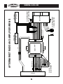
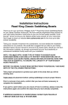
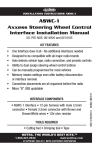
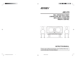
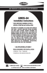
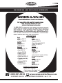
GM ONSTAR LAN DATA BUS INTERFACE
GMOS-LAN-01
Installation Instructions
Not compatible with amplified sound systems
* READ IMPORTANT WARNING ON PAGE 1
BEFORE ATTEMPTING ANY INSTALLATION
The GMOS-LAN-01 is designed to retain Onstar and retain the warning
chimes that are normally lost when the OEM radio is removed. It
also provides a 12 volt accessory output for proper aftermarket
radio operation. THE GMOS-LAN-01 also PROVIDES a MUTE,
PARKING BRAKE, VSS OR SPEED SENSE, AND A REVERSE OUTPUT TO MAKE INSTALLING AN AFTERMARKET NAVIGATIONAL
RADIO SIMPLER AND LESS TIME CONSUMING.
APPLICATIONS
GMC
Buick
• Enclave 2007-11
•Acadia 2007-11
• Lucerne 2006-10
•Savanna 2008-10
Cadillac
•Sierra (New body) 2007-11
• DTS 2006-10
•Yukon / XL 2007-10
• SRX 2007-09
Hummer
Chevrolet
•H2 2008-09
• Avalanche 2007-10
Pontiac
• Aveo 2009-10 *
•Torrent 2007-09
• Equinox 2007-09
• Vibe 2010 *
• Express 2008-10
*( Only required for retention of Onstar• Impala 2006-10
NAV outputs not applicable)
• Monte Carlo 2006-07
Saturn
• Silverado (new body)
2007-11
•Outlook 2007-09
• Suburban 2007-10
•Vue 2008-09
• Tahoe 2007-11
Suzuki
• Traverse 2009-11
•XL-7 2007-09
INTERFACE COMPONENTS
• GMOS-LAN-01 Interface
• 14 pin harness with stripped leads
• 12 pin to 30 pin GM harness
1-800-221-0932
www.axxessinterface.com
© COPYRIGHT 2004-2010 METRA ELECTRONICS CORPORATION Rev. 12-1-10
GMOS-LAN-01
* READ IMPORTANT WARNING
BEFORE ATTEMPTING ANY INSTALLATION
* IMPORTANT WARNING
THIS PRODUCT INCLUDES INSTRUCTIONS FOR INSTALLATION WHICH
MUST BE CAREFULLY FOLLOWED. THE INSTRUCTIONS ARE WORDED IN
SUCH A MANNER TO ASSUME THAT THE INSTALLER IS CAPABLE OF COMPLETING THESE TYPE OF ELECTRONIC INSTALLATIONS. IF YOU ARE
UNCLEAR AS TO WHAT YOU ARE INSTRUCTED TO DO OR BELIEVE THAT
YOU DO NOT UNDERSTAND THE INSTRUCTIONS SO AS TO PROPERLY AND
SAFELY COMPLETE THE INSTALLATION YOU SHOULD CONSULT A TECHNICIAN WHO DOES HAVE THIS KNOWLEDGE AND UNDERSTANDING.
FAILURE TO FOLLOW THESE INSTRUCTIONS CAREFULLY AND TO
INSTALL THE INTERFACE AS DESCRIBED COULD CAUSE HARM TO THE
VEHICLE OR TO SAFETY SYSTEMS ON THE VEHICLE. INTERFERENCE
WITH CERTAIN SAFETY SYSTEMS COULD CAUSE HARM TO PERSONS
AS WELL.
IF YOU HAVE ANY QUESTIONS IN THIS REGARD PLEASE CALL THE
METRA HELP LINE AT: 1-800-221-0932 FOR ASSISTANCE.
KNOWLEDGE IS POWER
Enhance your installation and fabrication skills by
enrolling in the most recognized and respected
mobile electronics school in our industry.
Log onto www.installerinstitute.com or call
800-354-6782 for more information and take steps
toward a better tomorrow.
We recommend MECP
certified technicians
1
We recommend MESA
certified technicians
GMOS-LAN-01
TOOLS REQUIRED FOR INSTALLATION
• Cutting Tool • Tape • Crimping Tool • Connectors (ie: butt-connectors, bell caps, etc.)
INSTALLING THE INTERFACE
* Important: Before beginning any of the following, disconnect the negative battery terminal to prevent accidental short circuit.
FOR INSTALLATION OF AFTERMARKET RADIO ONLY:
From the 14 pin harness:
1. Connect the red wire to the ignition/accessory wire of the aftermarket radio.
2. Connect the orange wire to the illumination wire of the aftermarket radio. If the aftermarket
radio has no illumination wire just tape off the orange wire.
3. Connect the Blue/white wire to the amp turn on wire of the aftermarket radio.
4. Connect the white wire to the left front positive speaker output of the aftermarket radio.
5. Connect the white/black wire to the left front negative speaker output of the aftermarket radio.
6. Connect the gray wire to the right front positive speaker output of the aftermarket radio.
7. Connect the gray/black wire to the right front negative speaker output of the aftermarket radio.
8. Connect the brown wire to the mute wire of the aftermarket radio. If the after market radio does not have
a Mute wire, tape up the brown wire.
The following wires on the 14 pin harness are for the aftermarket radios that have navigation built in:
1. Connect the green wire to the parking brake wire of the aftermarket navigation radio.
2. Connect the blue/pink wire to the VSS or speed sense wire of the aftermarket navigation radio.
3. Connect the green/purple wire to the reverse wire of the aftermarket navigation radio.
From the 12 pin harness:
1. Connect theYellow wire to the 12 volt constant/battery wire of the aftermarket radio.
2. Connect the Black wire to the ground wire of the aftermarket radio.
3. The Black/Yellow and Black/White wires will be discussed later in this manual.
From the 30 pin GM harness:
1. Connect the Green wire to the left rear positive speaker output of the aftermarket radio.
2. Connect the Green/Black wire to the left rear negative speaker output of the aftermarket radio.
3. Connect the Purple wire to the right rear positive speaker output of the after-market radio.
4. Connect the Purple/Black wire to the right rear negative output of the aftermarket radio.
(See wiring diagram 1 on page 3
2
3
CHIME VOLUME
ADJUSTMENT
RADIO
RF+
RF-
ORANGE
BLUE/WHITE
RED
LF+
LF-
YEL
DIAGR
RAM 1
L
LRRR+
R
RR-
L
LR+
GMOS-LAN-01
BLK
GM 30 PIN
BLACK/YELLOW
BLACK/WHITE
7 WIRES
GMOS-LAN-01
GMOS-LAN-01
FOR AFTERMARKET RADIO AND AMPLIFIER
(See wiring diagram on page 6)
CONNECTIONS TO BE MADE ON THE 14 PIN HARNESS:
1. Connect the red wire to the ignition/accessory wire of the aftermarket radio.
2. Connect the Orange wire to the illumination wire of the aftermarket radio. If the aftermarket radio
has no illumination wire just tape off the orange wire.
3. Connect the blue/white wire to the amp turn on wire of the aftermarket radio and to the blue/white wire in
the 24 pin harness.
4. White NOT USED
5. White/black NOT USED
6. Gray NOT USED
7. Gray/black NOT USED
8. Connect the Brown wire to the mute wire of the aftermarket radio. If the after market radio does not have a
Mute wire, tape up the Brown wire.
The following wires on the 14 pin harness are for the aftermarket radios that have navigation built in:
1. Connect the Green wire to the parking brake wire of the aftermarket navigation radio.
The following wires on the 14 pin harness are for the aftermarket radios that have navigation built in:
2. Connect the Blue/Pink wire to the VSS or speed sense wire of the aftermarket navigation radio.
3. Connect the Green/Purple wire to the reverse wire of the aftermarket navigation radio.
When completed, plug the 14 pin harness into the GMOS-LAN-01.
CONNECTIONS TO BE MADE ON THE 30 PIN GM HARNESS:
1. Connect the green wire to the amplifier’s left rear positive speaker output.
2. Connect the the green/black wire to the amplifier’s left rear negative speaker output.
3. Connect the purple wire to the amplifier’s right rear positive speaker output.
4. Connect the purple/black wire to the amplifier’s right rear negative speaker output.
5. Cut the white wire about half way between the two plugs. Connect the white wire from the 24 pin plug to
amplifier’s left front positive speaker output wire. Connect the white wire from the 12 pin plug to the positive
speaker wire of the Metra SP-2003 or equivalent.
6. Cut the white/black wire about half way between the two plugs. Connect the white/black wire from the 24
pin plug to amplifier’s left front negative speaker output wire. Connect the white/black wire from the 12 pin
plug to the negative speaker wire of the Metra SP-2003 or equivalent.
4
GMOS-LAN-01
7. Cut the gray wire about half way between the two plugs. Connect the gray wire from the 24 pin plug to amplifier’s right front positive speaker output wire. Connect the gray wire from the 12 pin plug to the positive
speakerwire of the Metra SP-2003 or equivalent.
8. Cut the gray/black wire about half way between the two plugs. Connect the gray/black wire from the 24 pin
plug to amplifier’s right front negative speaker output wire. Connect the gray/black wire from the 12 pin plug
to the negative speaker wire of the Metra SP-2003 or equivalent.
Note: If only one SP-2003 is used tape up the gray wires that would normally connect to the second
SP-2003 to avoid a short circuit.
CONNECTIONS TO BE MADE ON THE 12 PIN HARNESS:
1. Connect the yellow wire to the radio’s 12 volt battery or memory wire.
2. Connect the black wire to the radio’s ground wire.
3. The black/yellow and black/white wire is for the Onstar volume adjustment. This will be discussed in the
Onstar and Chime Level Adjustment section of this instruction.
When completed, plug the 12 pin harness into the GMOS-LAN-01.
FINAL WIRING CONNECTIONS
STRIP
Make wiring connections using the EIA color code chart shown below and the
instructions included with the head unit. Metra recommends making connections as shown below; Strip, Splice, Solder, Tape. Isolate and individually tape
off ends of any unused wires to prevent electrical short circuit.
SPLICE
SOLDER
TAPE
METRA/EIA WIRING CODE
Right Front (+) . . . . . . . . . . . . Gray
12V Ignition / Acc. . . . . . . . . . Red
12V Batt / Memory. . . . . . . . . Yellow
Right Front (-). . . . . . . . . . . . . Gray / Black
Ground. . . . . . . . . . . . . . . . . . Black*
Left Front (+) . . . . . . . . . . . . . White
Power Antenna. . . . . . . . . . . . Blue
Left Front (-). . . . . . . . . . . . . . White / Black
Amp Turn-On . . . . . . . . . . . . . Blue / White
Right Rear (+) . . . . . . . . . . . . Violet
Amp Ground. . . . . . . . . . . . . . Black / White
Right Rear (-) . . . . . . . . . . . . . Violet / Black
Illumination . . . . . . . . . . . . . . Orange
Left Rear (+) . . . . . . . . . . . . . Green
Dimmer . . . . . . . . . . . . . . . . . Orange / White
Left Rear (-) . . . . . . . . . . . . . . Green / Black
5
6
CHIME VOLUME
ADJUSTMENT
RF+
RF -
LF+
LF-
ORANGE/WHITE
RED
GREEN
BLUE/PINK
GREEN/PURPLE
BROWN
BLUE/WHITE
14 PIN
RADIO
GMOS-LAN-01
BLK
YEL
X
X
X
X
+
LR LR +
RR RR
BLACK/YELLOW
BLACK/WHITE
LF+
LF RF +
RF -
SP-2003
TO AFTERMARKET
REAR AMPLIFIER
GM 30 PIN
TO AFTERMARKET
FRONT AMPLIFIER
OPTIONAL
SP-2003
12 PIN
REQUIRED
AFTERMARKET RADIO AND AMPLIFIER WIRING
GMOS-LAN-01
GMOS-LAN-01
INSTALLING THE GMOS-LAN-01
1. With all connections completed, plug the 14 and 12 pin harnesses into the GMOS-LAN-01.
2. Reconnect the negative battery terminal.
3. Plug the 30 pin GM harness into the vehicle side harness, and plug the aftermarket radio harness into the
aftermarket radio.
4. Cycle the key by turning the ignition on then back off, then back on again to test the radio.
TESTING THE GMOS-LAN-01
1. Turn the ignition on, and then turn the aftermarket radio on.
2. Push the Onstar button, the radio should turn off and you should hear Onstar. Push the Onstar cancel button
and the radio should come back on.
CHIME VOLUME ADJUSTMENT
To adjust the chime volume, use a small screwdriver to rotate the potentiometer, located on the 14 pin harness side
of the interface, clockwise to make the chime louder and counterclockwise to make the chime softer.
ONSTAR LEVEL ADJUSTMENT
To adjust the Onstar volume level find the Black/Yellow wire on the 12 pin harness. Push the blue Onstar button,
while the voice is speaking tap the Black/Yellow wire to ground. There are 4 volume settings for Onstar; once the
4th setting is reached and the Black/Yellow wire is tapped to ground it will automatically go back to the first volume setting. Once the volume is set it will stay at that volume until the Black/Yellow wire is tapped to ground
again. This can be set during installation and then left alone. If user adjustment is desired, a momentary contact
switch (sold separately) can be added. Connect one terminal from the switch to ground and the other terminal to the
Black/Yellow wire. The volume will change one level every time the switch is pressed.
AUDIBLE TURN SIGNAL
When the factory radio is removed the audible turn signal indicator is lost.
If that turn signal “clicking” is desired follow these steps:
1. Using a SPDT relay (Metra part # E-123), connect pin #85 to the Black/White wire in the 12 pin harness.
2. . Connect pin #86 to the 12 volt constant wire on the 12 pin harness.
3 . Be sure to cover the other leads of the relay by either using female spade connectors or using tape to cover
the leads.
Now when the turn signal is on, the relay will make the audible “clicking” noise.
1-800-221-0932
www.axxessinterface.com
REV. 12/1/10 © COPYRIGHT 2004-2009 METRA ELECTRONICS CORPORATION INSTGMOS-LAN-01
7