1
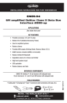
GMOS-LAN-04
GMOS-LAN-04
GM ONSTAR LAN DATA BUS INTERFACE
* IMPORTANT WARNING
GMOS-LAN-04
THIS PRODUCT INCLUDES INSTRUCTIONS FOR INSTALLATION WHICH
MUST BE CAREFULLY FOLLOWED. THE INSTRUCTIONS ARE WORDED
IN SUCH A MANNER TO ASSUME THAT THE INSTALLER IS CAPABLE
OF COMPLETING THESE TYPE OF ELECTRONIC INSTALLATIONS. IF YOU
ARE UNCLEAR AS TO WHAT YOU ARE INSTRUCTED TO DO OR BELIEVE
THAT YOU DO NOT UNDERSTAND THE INSTRUCTIONS SO AS TO
PROPERLY AND SAFELY COMPLETE THE INSTALLATION YOU SHOULD
CONSULT A TECHNICIAN WHO DOES HAVE THIS KNOWLEDGE AND
UNDERSTANDING. FAILURE TO FOLLOW THESE INSTRUCTIONS
CAREFULLY AND TO INSTALL THE INTERFACE AS DESCRIBED COULD
CAUSE HARM TO THE VEHICLE OR TO SAFETY SYSTEMS ON THE
VEHICLE. INTERFERENCE WITH CERTAIN SAFETY SYSTEMS COULD
CAUSE HARM TO PERSONS AS WELL. IF YOU HAVE ANY QUESTIONS
IN THIS REGARD PLEASE CALL THE HELP LINE OR THE METRA AT
1-800-221-0932 FOR ASSISTANCE.
INSTALLATION INSTRUCTIONS
For amplified sound systems only
* READ IMPORTANT WARNING ON PAGE 1
BEFORE ATTEMPTING ANY INSTALLATION
The GMOS-LAN-04 is designed to retain the amplified sound systems, retain Onstar, and retain the
warning chimes that are normally lost when the
OEM radio is removed. It also provides a 12 volt
accessory output for proper aftermarket radio
operation. THE GMOS-LAN-04 also PROVIDES a
MUTE, PARKING BRAKE, VSS OR SPEED SENSE,
AND A REVERSE OUTPUT TO MAKE INSTALLING
AN AFTERMARKET NAVIGATIONAL RADIO SIMPLER AND LESS TIME CONSUMING.
APPLICATIONS
Chevrolet
•Cobalt 2007-10
•HHR 2006-10
•Malibu 2008-11
Pontiac
•G5 2007-09
•G6 2009-10
•Solstice 2006-09
Saturn
•Aura 2006-09
•Sky 2006-09
INTERFACE COMPONENTS
• GMOS-LAN-04 Interface
• 14 pin harness with rca’s
• 16 pin to 30 pin GM harness
REV. 12/1/10
1-800-221-0932
1
INSTGMOS-LAN-04
www.metraonline.com
©Copyright 2004-2010 Metra Electronics Corporation
1-800-221-0932
www.metraonline.com
©Copyright 2004-2010 Metra Electronics Corporation
GMOS-LAN-04
TOOLS REQUIRED FOR INSTALLATION
INSTALLING THE GMOS-LAN-04
ONSTAR LEVEL ADJUSTMENT
• Cutting Tool • Tape • Crimping Tool • Connectors (I.E. butt-connectors, bell
caps, ECT…)
1. With all the connections completed, plug the 14 and 16 pin harnesses into
To adjust the Onstar volume level find the Black/Yellow wire on the 16 pin
harness. Push the blue Onstar button, while the voice is speaking tap the
Black/Yellow wire to ground. There are 31 volume settings for Onstar;
once the 31st setting is reached and the Black/Yellow wire is tapped to
ground it will automatically go back to the first volume setting. Once the
volume is set it will stay at that volume until the Black/Yellow wire is
tapped to ground again. If the user would like to adjust the Onstar volume
without having to get to the GMOS-LAN-04 interface, a 10K potentiometer
from Radio Shack (part # 271-1715) can be wired in. Connect one side of
the potentiometer to the Black/Yellow wire and connect the other side to
ground. Mount the potentiometer in a convenient location that is easy to
reach.
WIRING CONNECTIONS
*Important: Before beginning any of the following, disconnect the negative
battery terminal to prevent an accidental short circuit.
1. From the 14 pin harness:
Connect the Red wire to the ignition/accessory wire of the aftermarket radio.
Connect the Blue/White wire to the amp turn on wire of the aftermarket radio.
Connect the White rca to the left front rca output of the aftermarket radio.
Connect the Gray rca to the right front rca output of the aftermarket radio.
Connect the Green rca to the left rear rca output of the aftermarket radio.
Connect the Purple rca to the right rear rca output of the aftermarket radio.
Connect the Brown wire to the mute wire of the aftermarket radio. If the aftermarket radio does not have a Mute wire, tape up the Brown wire.
The following wires on the 14 pin harness are for the aftermarket radios
that have navigation built in:
Connect the Green wire to the parking brake wire of the aftermarket navigation
radio.
Connect the Blue/Pink wire to the VSS or speed sense wire of the aftermarket
navigation radio.
Connect the Green/Purple wire to the reverse wire of the aftermarket navigation radio.
2. From the 16 pin harness:
Connect the Yellow wire to the 12 volt constant/battery wire of the
aftermarket radio.
Connect the Black wire to the ground wire of the aftermarket radio.
Connect the Orange wire to the illumination wire of the aftermarket radio.
If no illumination wire is present, tape up the Orange wire.
The Black/Yellow wire will be discussed later in this manual.
3. Connect the two pin harness from the 30 pin connector to the two pin
connector located on the 12 pin harness side of the GMOS-LAN-04.
the GMOS-LAN-04.
2. Reconnect the negative battery terminal.
3. Plug the 30 pin GM harness into the vehicle side harness, and plug the
aftermarket radio harness into the aftermarket radio.
4. Cycle the key by turning the ignition on then back off, then back on again to
test the radio.
TESTING THE GMOS-LAN-04
Turn the ignition on, and then turn the aftermarket radio on. Push the Onstar
button, the radio should turn off and you should hear Onstar. Push the Onstar
cancel button and the radio should come back on.
CHIME VOLUME ADJUSTMENT
If the chime is too loud, remove the bottom shunt jumper that is next to the 14
pin harness side of the interface. (See diagram) This will lower the chime volume.
AUDIBLE TURN SIGNAL
AUDIO LEVEL ADJUSTMENT
If the audio level is too distorted or way too low under normal listening levels, to
correct this there is a potentiometer on the 14 pin side of the interface. Using a
small screwdriver turn the potentiometer counterclockwise to lower the input signal, and turn the potentiometer clockwise to raise the input signal.
Note: The chime and turn signal volume will adjust with the audio input.
When the factory radio is removed the audible turn signal indicator is lost. The
GMOS-LAN-04 will emulate the audible turn signal heard through the left front
speaker. If the turn signal if too loud remove the top shunt jumper that is next to
the 14 pin harness side of the interface. (See diagram) This will lower the audible
turn signal.
Programming Bluetooth function
through steering wheel (If equipped)
1. Turn on ignition and radio
2. Press and hold the phone button on the steering wheel
3. After you hear the audible sound ready release the button
4. Enjoy your Bluetooth
2
3
4