1
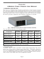
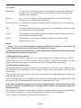
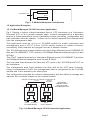
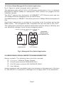
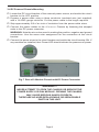
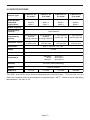
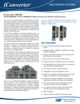
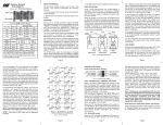
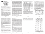
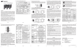
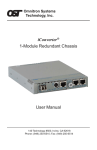
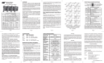
iConverter® 2-Module Power Chassis User Manual 140 Technology Dr., #500 Irvine, CA 92618 USA Phone: (949) 250-6510; Fax: (949) 250-6514 Page 1 Warning The operating description in this Instruction Manual is for use by qualified personnel only. To avoid electrical shock, do not perform any servicing of this module other than that contained in the operating instructions, unless you are qualified and certified to do so by Omnitron Systems Technology, Inc. Caution All user-required operations can be performed without opening the chassis. Never attempt to open or remove the cover or tamper with the chassis. There are no user replaceable or serviceable parts in this unit. Equipment is not intended to be installed and used in a place (home, school, or public area) accessible to the general population. Warranty This product is warranted to the original purchaser against defects in material and workmanship for a period of TWO YEARS from the date of shipment. A LIFETIME warranty may be obtained by the original purchaser by REGISTERING this product with Omnitron within 90 days from the date of shipment. TO REGISTER, COMPLETE AND MAIL OR FAX THE ENCLOSED REGISTRATION FORM. Or you may register your product on the Internet at http://www.omnitron-systems.com. During the warranty period, Omnitron will, at its option, repair or replace a product which is proven to be defective. For warranty service, the product must be sent to an Omnitron designated facility, at Buyer’s expense. Omnitron will pay the shipping charge to return the product to Buyer’s designated US address using Omnitron’s standard shipping method. Limitation of Warranty The foregoing warranty shall not apply to defects resulting from improper or inadequate use and/or maintenance of the equipment by Buyer, Buyer-supplied equipment, Buyersupplied interfacing, unauthorized modifications or tampering with equipment (including removal of equipment cover by personnel not specifically authorized and certified by Omnitron), or misuse, or operating outside the environmental specification of the product (including but not limited to voltage, ambient temperature, radiation, unusual dust, etc.), or improper site preparation or maintenance. No other warranty is expressed or implied. Omnitron specifically disclaims the implied warranties of merchantability and fitness for any particular purpose. Exclusive Remedies The remedies provided herein are the Buyer’s sole and exclusive remedies. Omnitron shall not be liable for any direct, indirect, special, incidental, or consequential damages, whether based on contract, tort, or any legal theory. Page 2 iConverter 2-Module Power Chassis User Manual 1. 0 GENERAL DESCRIPTION The iConverter 2-Module Power Chassis is powered by a single internal universal AC or DC power supply and can accommodate up to two iConverter media converters. It is ideal for enterprise Local Area Network (LAN) or Metropolitan Area Network (MAN) applications where remote management and explicit demarcation between the service provider’s equipment and customer’s equipment is required. Fig. 1 2-Module Chassis (Shown without modules installed) This User Manual describes the following models: 2-Module AC 8.5 watts 2-Module AC 16.5 watts 2-Module DC 6.6 watts 2-Module DC 16.5 watts 2-Module Chassis 8230-0 8231-0 8235-0 8236-0 2-Module Chassis with Dying Gasp Support 8230-1 8231-1 8235-1 8236-1 Wall-Mount Hardware Kit 8249-0 8249-0 8249-0 8249-0 Blank Module Panel 8090-0 8090-0 8090-0 8090-0 Configuration For wide temperature (-40 to 60º C), add a "W" to the end of the model number. Consult factory for extended temperature (-40 to +75º C) models. 1.1 Dying Gasp Trap The 8230-1, 8231-1, 8235-1 and 8236-1 chassis feature Dying Gasp Trap, which reports loss of power input or chassis power supply failure. This feature requires an iConverter management module be installed in the chassis. When power failure occurs, the chassis reserves enough power to keep the installed modules running in order to send a final SNMP alert to the management software. Page 3 1.2 Terms Backplane A printed circuit board which is permanently mounted inside the chassis and is populated with receptacle connectors into which modules are inserted. Module An iConverter plug-in card positioned into a slot location and inserted into a backplane connector. Module-Guide A mechanical channel guiding module insertion into a backplane connector. Slot A single chassis position consisting of a backplane connector and its associated module-guides. A Link A backplane slot-to-slot connection that provides Ethernet connectivity between adjacent slots. A Port An interface on a module capable of Ethernet traffic via the backplane’s A Link. Notes: 1. Other iConverter multi-module chassis models also support a backplane B Link. This feature is not required on the 2-Module Chassis. 2. Other modules support a B Port. In the application drawings in this manual, the B Ports depicted are not connected. 1.3 Mechanical Description The 2-Module chassis consists of a fixed internal AC (models 8230-0, 8230-1, 8231-0 and 8231-1) or DC (models 8235-0, 8235-1, 8236-0 and 8236-1) power supply that provides power to the chassis’ two (2) backplane connectors. 1.4 Backplane Architecture The chassis features two (2) module slots numbered 1 (top slot) and 2 (bottom slot). As modules are inserted into the chassis slots, they are seated into the slot connectors. The two slots are connected using the A Link which provides Ethernet connectivity between the two slots. When modules with A Port capability are inserted into the adjacent chassis slots, they can connect their Ethernet data using their A Ports and the A Link. Note: Not all modules support and have backplane ports. To find out about each specific module’s backplane port configuration, refer to the specific module’s documentation. This chassis’ architecture facilitates a variety of applications including unmanaged, out-of-band managed, in-band managed and multi-port configurations. Fig 2. Depicts the chassis’ backplane architecture. Page 4 Slot 1 Connector A Backplane Link Slot 2 Connector Fig. 2 2-Module Backplane Architecture 1.5 Application Examples 1.5.1 In-Band Managed 10/100 Converter Application Fig 3. Depicts a typical in-band managed fiber to UTP conversion at a Customer’s Premises (CP) or at a remote network edge. In-band management is a desirable feature in these applications since it facilitates remote monitoring, configuration and trap notification from the chassis. VLANs can be used to separate the customer data from the management data. This application uses an iConverter 10/100M module for media conversion and management and a 4TxVT 4-Port 10/100 switch module for added customer connectivity. Both modules are plugged into the 2-Module chassis. The 10/100M converter module features two front-plane Ethernet ports (100BASE-FX fiber and 10/100BASE-T UTP) and two 10/100Mbps Ethernet backplane ports (A and B Ports). The 4TxVT module features four front-plane Ethernet ports (10/100BASE-T) and two 10/100Mbps Ethernet backplane ports (A and B Ports). The user data flows between the fiber and UTP ports of the 10/100M and 4TxVT via the backplane. The management data flows between the fiber and all the UTP ports (in-band). Using a management VLAN, the management data is recognized by the 10/100M module and is not shared by the other ports. This configuration provides the network administrator with the ability to manage and maintain the converter chassis at the remote location. Chassis Backplane “A” Link A Port B Port Internal 10/100 switch chip Fiber 100 port UTP 10/100 port 10/100M Module A Port B Port Note that the 2-Module Chassis does not include the B Backplane Link Internal 10/100 switch chip 4-port 10/100 UTP Switch 4TxVT Module Fig. 3 In-Band Managed 10/100 Converter Application Page 5 1.5.2 Out-of-Band Managed 4-Port Switch Application Fig 4. Depicts a typical managed switch application. This application uses a 4TxVT 4-Port 10/100 switch module and an iConverter Network Management Module (NMM) for management. Both modules are plugged into the 2-Module chassis. The 4TxVT features four front-plane 10/100BASE-T UTP Ethernet ports and two 10/100Mbps Ethernet backplane ports (A and B Ports). The NMM features a 10BASE-T front-plane port and a 10Mbps Ethernet backplane A Port. Out-of-band management is provided by connecting to the front-plane port on the NMM module. The management data is separate from the user data on the 4TxVT. This configuration provides the network administrator with the ability to efficiently and cost effectively manage a small (4-port) workgroup switch. Chassis Backplane “A” Link A Port A Port B Port Note that the 2-Module Chassis does not include the B Backplane Link Internal 10/100 switch chip NMM NMM UTP 10 port NMM Module 4-port 10/100 UTP Switch 4TxVT Module Fig. 4 Managed 4-Port Switch Application 2.0 UNPACKING, VISUAL INSPECTION AND INVENTORY Review contents. The following items should be included: iConverter 2-Module Power Chassis One AC power cord (AC MODULES ONLY) One DC power connector (DC MODULES ONLY) User Manual Inspect equipment and immediately report any damage or discrepancies to Omnitron at 949-250-6510. If equipment is damaged, do not apply power to the equipment. Page 6 3.0 SITE PREPARATION AND INSTALLATION 3.1 AC Powered Chassis Site Preparation Power source should be available within 5 ft. of the chassis and installed per the National Electrical Code ANSI/NFPA-70. This equipment requires a 100-240VAC, 0.5Amp, 50/60Hz power outlet. Appropriate overloading protection should be provided on the AC power source outlets utilized. The standard operating temperature of this equipment is 0 to 50 degrees C. If installed in a closed or multi-module rack assembly, the operating ambient temperature of the rack must not exceed the maximum rated 50 degrees C. See specifications on page 10 for wide temperature ranges. Installation of the equipment should be such that the air flow in the front, back and side vents of the chassis are not compromised or restricted. Never use this equipment to carry any weight except its own. Never use it as a shelf to support the weight of other equipment. 3.2 AC Powered Chassis Mounting Attach the AC power cords to the back of the Power Receptacle and plug into the AC outlet. Any installed iConverter modules will illuminate the power LED. Fig. 6 Rear of 2-Module Chassis with Power Cord 3.3 DC Powered Chassis Site Preparation Power source should be available within 5 ft. of the chassis. The over current protection for connection with centralized DC shall be provided in the building installation, and shall be a UL listed circuit breaker rated 20 Amps, and installed per the National Electrical Code, ANSI/NFPA-70. This equipment requires 18-60VDC/1.0Amp (8235) or 2.0Amp (8236) rated power. Appropriate overloading protection should be provided on the DC power source outlets utilized. WARNING: Only a DC power source that complies with safety extra low voltage (SELV) requirements can be connected to the DC-input power supply. Page 7 WARNING REGARDING EARTHING GROUND: o This equipment shall be connected to the DC supply system earthing electrode conductor or to a bonding jumper from an earthing terminal bar or bus to which the DC supply system earthing electrode is connected. o This equipment shall be located in the same immediate area (such as adjacent cabinets) as any other equipment that has a connection between the earthed conductor of the same DC supply circuit and the earthing conductor, and also the point of earthing of the DC system. The DC system shall not be earthed elsewhere. o The DC supply source is to be located within the same premises as this equipment. o There shall be no switching or disconnecting devices in the earthed circuit conductor between the DC source and the earthing electrode conductor. The standard operating temperature of this equipment is 0 to 50 degrees C. If installed in a closed or multi-module rack assembly, the operating ambient temperature of the rack must not exceed the maximum rated 50 degrees C. See specifications on page 10 for wide temperature ranges. Installation of the equipment should be such that the air flow in the front, back and side vents of the chassis are not compromised or restricted. Never use this equipment to carry any weight except its own. Never use it as a shelf to support weight of other equipment. Page 8 3.4 DC Powered Chassis Mounting Locate the DC circuit breaker of the external power source, and switch the circuit breaker to the OFF position. Prepare a power cable using a three conductor insulated wire (not supplied) with a 14 AWG gauge minimum. Cut the power cable to the length required. Strip approximately 3/8 of an inch of insulation from the power cable wires. Connect the power cables to the iConverter Chassis by fastening the stripped ends to the DC power connector. WARNING: Note the wire colors used in making the positive, negative and ground connections. Use the same color assignment for the connection at the circuit breaker. Connect the power wires to the circuit breaker and switch the circuit breaker ON. If any modules are installed, their Power LED should indicate the presence of power. Fig. 7 Rear of 2-Module Chassis with DC Power Connector WARNING!!! NEVER ATTEMPT TO OPEN THE CHASSIS OR SERVICE THE POWER SUPPLY OR FAN MODULE. OPENING THE CHASSIS MAY CAUSE SERIOUS INJURY OR DEATH. THERE ARE NO USER REPLACEABLE OR SERVICEABLE PARTS IN THIS UNIT. Page 9 4.0 SPECIFICATIONS Chassis Type Model Number Standard Dying Gasp 2-Module AC 8.5 watts 2-Module AC 16.5 watts 2-Module DC 6.6 watts 2-Module DC 16.5 watts 8230-0 8230-1 8231-0 8231-1 8235-0 8235-1 8236-0 8236-1 Module Capacity 2 Power Supply Capacity Fixed Internal Input Power Requirements (typical) 100 to 240VAC, 50/60Hz 0.5A @ 120VAC 100 to 240VAC, 50/60Hz 0.5A @ 120VAC +/- 18 to 60VDC -48VDC @ 1.0A +/- 18 to 60VDC -48VDC @ 2.0A Backplane Power 2.6A @ 3.3VDC 1.5A per slot 5A @ 3.3VDC 2.5A per slot 2A @ 3.3VDC 1.5A per slot 5A @ 3.3VDC 2.5A per slot Dimensions W:6.7" x D:5.51" x H:1.87" Weight 2.5 lbs Compliance UL, CE, FCC Class A, NEBS Level 3 Standard: Wide: Storage: Temperature 0 to 50º C -40 to 60º C -40 to 80º C Humidity 5 to 95% (non-condensing) Altitude -100m to 4000m MTBF(hrs) 151,000 413,000 329,000 538,000 The 8231 and 8236 have internal temperature-controlled fans. The fan will turn on when the chassis internal temperature is greater then ~40oC. Under normal operating temperature, the fan is off. Page 10 5.0 CUSTOMER SUPPORT INFORMATION If you encounter problems while installing this product, contact Omnitron Technical Support: Phone: (949) 250-6510 Fax: (949) 250-6514 Address: Omnitron Systems Technology, Inc. 140 Technology Dr., #500 Irvine, CA 92618, USA Email: [email protected] URL: www.omnitron-systems.com Page 11 040-08230-001J 02/08 Page 12