1
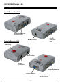
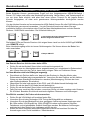
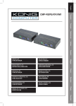
Cat.5 USB KVM Extender Lite User Manual Benutzerhandbuch Manuel Utilisateur Manuale d’uso English Deutsch Français Italiano LINDY No. 32338 www.lindy.com © LINDY ELECTRONICS LIMITED & LINDY-ELEKTRONIK GMBH - FIRST EDITION (June 2005) Product Information 2 User Manual 3 Benutzerhandbuch 6 Manuel Utilisateur 9 Manuale d’uso 12 1 USB KVM Extender Lite Product Information Local Transmitter Unit Computer/KVM Switch Connection Ports Console Connection Ports RJ-45 Connection Remote Receiver Unit VGA Tuning Control Power Adapter Connection RJ-45 Connection Computer/KVM Switch Connection Ports Console VGA Port Console Keyboard & Mouse Ports 2 User Manual English Introduction Thank you for purchasing the LINDY Cat.5 USB KVM Extender Lite. The USB KVM Extender LITE allows you to control your PC, server or USB KVM switch from a USB keyboard, mouse and VGA monitor at distances of up to approximately 150 metres (500 feet) away, using low cost CAT5 or higher cable. This extender supports USB mouse and keyboard operation only. It does not support other USB signals! The USB KVM Extender LITE consists of a Transmitter (Local) unit and a Receiver (Remote) unit. The Transmitter connects to a computer or USB KVM switch. The Receiver unit is located at a remote location and connects to a keyboard, monitor and mouse console. The USB KVM Extender LITE offers all the features of a professional KVM extender. A workstation can be connected to the Receiver unit allowing the operator to work on his computer or remotely on the remote computer or KVM switch. Additionally, a local console can be connected to the Transmitter unit for direct access to the KVM switch. Both local and remote consoles can access the servers connected to the KVM switch simultaneously, governed by a short timeout. Using the USB KVM Extender LITE to remotely access a computer: Local Computer Remote Operators PC Local Console Remote Console Remote Receiver Up to 150m Local Transmitter Features Provides a convenient and secure method of remotely locating workstations or servers without compromising convenience and control Supports USB keyboard/mouse and VGA monitor signals Dual console operation – control your computer / KVM Switch from both local and remote locations Remote Receiver unit features a built-in KVM Switch – allowing control of a local PC High-resolution video support: 1280 x 1024 @ 100m 800 x 600 @ 150m Adjustable VGA Tuning control to improve video quality Easy, user-friendly installation – no software required – the unit registers in the device manager as a USB KVM device Compatible with all major operating systems with USB support for KVM devices Package Contents Local Transmitter unit Remote Receiver unit 12V DC, 1A Power Adapter (for the Remote Receiver unit) 2 x 2-in-1 KVM cable (USB & VGA) This manual 3 User Manual English Installation Note: If you experience problems with mouse functionality, try using the same brand and model of mouse on both local and remote units. Make sure all of your computers and peripherals are switched OFF before proceeding with the installation. Local Transmitter Unit 1. Connect your keyboard, mouse and monitor to the Local Console ports on the Transmitter. 2. Using a 2-in-1 USB KVM cable, connect the ports labelled PC / KVM on the Transmitter unit to the USB and video ports on your computer, or the USB and video control console ports on your KVM switch. 3. Connect a CAT5 (or higher) network cable of appropriate length to the RJ-45 port Remote Receiver Unit 1. Connect your USB keyboard, mouse and monitor to the ports on the Remote unit. 2. Using the supplied 2-in-1 KVM cable, connect the USB and video ports labelled LOCAL PC to the USB and video ports on your local PC. 3. Connect a CAT5 (or higher) network cable to the RJ-45 port 4. Connect the power supply jack to the port on the Remote unit. Plug the power supply into the mains Powering up and checking the installation 1. Power on the PC connected to the Remote Receiver unit and then power on the PC / KVM Switch installation connected to the Local Transmitter unit. 2. Check the display quality at the Remote Receiver console. Rotate the VGA Tuning control to adjust the picture quality. If this does not provide a good enough picture quality you may get better results with higher quality CAT6 network cable. The picture quality of any CAT5 Extender degrades with increasing cable length. Up to a resolution of 1280x1024@80Hz and a cable length of 100m there should be no significant shadows, but a more or less clear picture. For higher resolutions this distance is reduced. For lower resolutions the picture quality may also be acceptable over longer cable lengths. LED Status Indicators Remote Receiver Unit LED LOCAL LOCAL REMOTE REMOTE STATUS RED FLASHING RED RED FLASHING RED MEANING The console is switched to the local workstation PC The console is switched to the workstation, but the PC is turned off or not connected. The console is switched to the remote computer / KVM Switch The console is switched to the remote computer / KVM Switch but the computer(s) are not connected or are switched off. Local Transmitter Unit LED POWER POWER STATUS STATUS STATUS OFF RED FLASHING RED OFF MEANING No computer(s) or KVM switch connected to the Local Transmitter. Computer(s) or KVM switch connected to the Local Transmitter. Flashes when there is local console keyboard/mouse activity. When there is no console keyboard/mouse activity this LED remains off. 4 User Manual English Keyboard hotkey commands (Remote Receiver only) Both consoles of the extender can have simultaneous access to the connected server or KVM switch. Active keyboard and mouse access is governed by a short timeout period. When you access from the local console of the Transmitter unit you can operate your USB KVM switch using its regular keyboard hotkeys. When you use the remote console you have two additional hotkeys that allow you to switch between your workstation and remote KVM access. You can switch console control at the Remote Receiver unit from PC port (connected workstation) to RJ-45 port (the PC / KVM switch connected to the Local Transmitter) using this simple hotkey command: Scroll Lock + Scroll Lock + C = select ‘PC Port’ or ‘RJ-45 Port’ (Remote KVM access) When switching, the appropriate LOCAL and REMOTE LED will light on the Remote unit. You will also hear an audible confirmation. You can enable and disable this audible beeper using this hotkey command: Scroll Lock + Scroll Lock + Q = Beeper ON/OFF Troubleshooting There are no LED’s illuminated on the Remote Receiver unit Ensure that the AC Adapter is plugged into the mains and the jack is plugged into the socket on the Remote Receiver. Verify that the connected PC is switched on. Otherwise display problems may result. There is no video signal displayed on the monitor Check that the VGA cables and CAT5 cable are properly connected to the respective ports on the Receiver and Transmitter units. Ensure the VGA cables are correctly connected to the computers. Make sure the computer is not in Stand-by mode or powered down. Make sure the power adapter is connected to the Receiver If you still can’t see a picture, try connecting with a shorter CAT5 patch cable to make sure there is not a fault with the longer CAT5 cable. The display is ‘foggy’ or unclear. Check that the VGA cables are properly connected. Try adjusting the VGA Tuning control as described in the Installation section Ensure that the VGA resolution is not set too high for the length of Ethernet cable that is used. Try a higher specification or shorter length CAT6 cable Try reducing the display resolution If results are still not satisfactory please refer to the final remarks in the Installation section 5 Benutzerhandbuch Deutsch Einführung Dieser KVM-Extender erlaubt Ihnen Monitor-, Maus- und Tastatursignale zu Ihrem PC oder USB KVM-Switch über günstiges Cat.5 Netzwerkkabel über Entfernungen bis 150m zu senden. Die USB-Ports unterstützen lediglich USB Maus- & Tastatursignale! Der USB KVM Extender LITE besteht aus einem Transmitter (Local Unit) und einem Receiver (Remote) Unit. Der Local Unit (Transmitter) wird am fernzubedienenden PC oder KVM Switch angeschlossen, der Receiver (Remote Unit) befindet sich (wie eine Fernbedienung: Remote Control) beim User. Die beiden Units werden mit preiswertem Netzwerkkabel Cat.5 oder höher verbunden. Der USB KVM Extender LITE stellt Ihnen alle Features eines KVM Extenders zur Verfügung: An der lokalen Seite am KVM Switch erlaubt er den Anschluss einer Konsole mit Monitor, Maus und Tastatur - für Wartungsarbeiten eine quasi unverzichtbare Option. Beide Konsolen können simultan arbeiten, der aktive Zugriff wird über einen kurzen Time-out geteilt. Und der Extender erlaubt am Büroarbeitsplatz den Anschluss eines Arbeitsplatzrechners für die tägliche Büroarbeit. Beispielkonfiguration mit einem PC Local Computer Remote Operators PC Local Console Remote Console Remote Receiver Bis 150m Kabellänge Local Transmitter Eigenschaften Erlaubt den bequemen komfortablen Remote Zugriff auf PCs, Server und USB-KVMSwitches aus Distanzen bis 150m Dual Console Betrieb: Je eine Arbeitskonsole an jeder Lokation Option Arbeitsplatzrechner: Der Remote Unit am Arbeitsplatz enthält einen KVMSwitch zum Umschalten zwischen Arbeitsplatzrechner und Remote KVM-Zugriff Unterstütz hohe VGA Auflösungen, z.B.: 1280 x 1024 bis 100m 800 x 600 bis 150m Einstellbare VGA Verstärkung und RGB-Laufzeitkalibrierung Einfach zu bedienen und zu installieren – keinerlei Softwareinstallation – meldet sich am System als USB KVM Device an Kompatibel zu allen weit verbreiteten Betriebssystemen mit USB Unterstützung für KVM Devices Lieferumfang, Packungsinhalt Local Transmitter Unit (am fern zu bedienenden PC / KVM-Switch) Remote Receiver Unit (am Arbeitsplatz) 12V DC, 1A Netzteil (für den Remote Receiver Unit) 2 x 2-in-1 KVM Kabel, 2m, zum Anschluss des lokalen Arbeitsplatzrechners und des fernbedienten KVM-Switch bzw. PC Dieses Handbuch 6 Benutzerhandbuch Deutsch Installation ACHTUNG: Falls Sie Probleme mit den Maus- und Tastatursignalen haben setzen Sie bitte identische Mäuse und Tastaturen local und remote ein! Schalten Sie alle angeschlossenen Rechner und Peripheriegeräte aus. Transmitter Local Unit 1. Schließen Sie ihre Maus, Tastatur und Monitor an die entsprechend gelabelten Ports am Local Unit an. 2. Schließen Sie den fernzusteuernden KVM-Switch oder PC mit einem 2-in-1 Kombi-KVMKabel an die Ports PC / KVM an. 3. Schließen Sie das Netzwerk-Verbindungskabel an den RJ-45-Port an. Remote Receiver Unit 1. Schließen Sie ihre Maus, Tastatur und Monitor an die entsprechend gelabelten Ports am Remote Unit an. 2. Schließen Sie den Arbeitsplatzrechner mit dem Kombi-KVM-Kabel an LOCAL PC an. 3. Schließen Sie das Netzwerk-Verbindungskabel an den RJ-45-Port an. 4. Schließen Sie das Netzteil an. Inbetriebnahme 1. Schalten Sie die Monitore und dann den Arbeitsplatzrechner und dann den fernzusteuernden PC bzw. den KVM Switch und ggf. die angeschlossenen Rechner ein. 2. Prüfen Sie die Bildqualität am Arbeitsplatzrechner wenn dieser remote zugreift. Durch Justierung des VGA-Tuning Reglers können Sie Laufzeitunterschiede der Einzelfarben RGB und die Verstärkung justieren. 3. Sollte dies nicht die gewünschten Ergebnisse erbringen, versuchen Sie eventuell noch ein anderes höherwertiges Netzwerkverbindungskabel oder kontaktieren Sie den Techniksupport von LINDY. Starke Farbsäume auf dem Monitor deuten auf nicht ausreichende Qualität des RJ-45 Verbindungskabel hin! Sollte auch dies nicht das gewünschte Ergebnis liefern so sollten Sie erwägen statt diesem Modell einen professionellen deutlich teureren High End KVM-Extender von LINDY zu einzusetzen. Bedeutung der LED Anzeigen Remote Receiver Unit LED LOCAL LOCAL REMOTE REMOTE STATUS ROT ROT BLINKEND ROT ROT BLINKEND BEDEUTUNG Diese Konsole greift gerade auf den Arbeitsplatz PC zu Diese Konsole greift gerade auf den Arbeitsplatz PC zu aber der Arbeitsplatz PC ist ausgeschaltet Diese Konsole greift gerade auf den Remote PC / KVM Switch zu Remote PC / KVM Switch nicht aktiv, möglicherweise Remote Rechner ausgeschaltet Local Transmitter Unit LED STATUS POWER AUS POWER ROT ROT BLINKEND AUS STATUS STATUS BEDEUTUNG Kein eingeschalteter PC oder KVM Switch angeschlossen (keine Stromversorgung von diesem) PC oder KVM Switch angeschlossen und eingeschaltet Aktiver Zugriff erfolgt von der lokalen Konsole am Local Unit Remote Konsole nicht aktiv bzw. ausgeschaltet 7 Benutzerhandbuch Deutsch Tastatur Hotkey Kommandos ( nur Remote Receiver ) Beide Konsolen können gemeinsamen Zugriff auf den ferngesteuerten USB-KVM-Switch / Server / PC haben und sehen das Monitorbild gleichzeitig. Aktiver Maus- und Tastaturzugriff ist nur von einer Seite möglich, wird aber über einen kurzen Timeout für die jeweils andere Konsole freigegeben, so dass auch gemeinsame Wartungsarbeiten durchgeführt werden können. Von der lokalen Konsole am fernzusteuernden KVM-Switch können Sie alle KVM-Hotkeys Ihres KVM-Switches ganz normal verwenden. Von der Remote Konsole aus haben Sie zwei zusätzliche Hotkeys, die zwischen dem Zugriff auf den Arbeitsplatzrechner und den Remote Rechner / KVM-Switch umschalten. Der Umschalt-Hotkey ist: Rollen + Rollen + C = Umschalten zwischen Arbeitsplatzrechner und Remote Zugriff am Remote Unit Die beiden LEDs am Remote Receiver Unit zeigen Ihnen visuell an ob Ihr KVM-Zugriff LOCAL oder REMOTE erfolgt. Beim Umschaltvorgang ertönt ein kurzer Quittierungston. Sie können diesen bei Bedarf einoder ausschalten: Rollen + Rollen + Q = Beeper ON/OFF Problemlösung Am Remote Receiver Unit leuchten keine LEDs Prüfen Sie ob das Netzteil Strom liefert und korrekt eingesteckt ist. Es sollte immer ein Arbeitsplatzrechner angeschlossen und mindestens im Ruhezustand sein. Wenn dies nicht der Fall ist, kann dies in einigen Fällen zu Problemen führen. Auf dem Monitor wird kein Bildsignal angezeigt Dies könnte ein Zeichen dafür sein, dass sich der Rechner im Standby Modus oder Ruhezustand befindet oder ausgeschaltet ist. Versuchen Sie den Rechner auf die übliche Weise aus dem Standby/Ruhezustand zu wecken (Mausbewegung, Drücken der Leeroder Großschreibtaste, Einschalten). Überprüfen Sie lokal und remote ob die PS/2- und VGA-Kabel korrekt befestigt sind. Prüfen Sie ob das das RJ-45-Kabel korrekt befestigt ist. Prüfen Sie ob das Netzteil Strom liefert und korrekt eingesteckt ist. Falls Sie immer noch kein Bild erhalten, versuchen Sie es mit einem anderen oder kürzeren RJ-45 Kabel. Beachten Sie bitte die maximal möglichen Distanzen und Auflösungen. Das Bild ist unscharf, die Farben sind verwaschen Prüfen Sie die VGA-Kabel auf korrekten festen Sitz. Versuchen Sie mit dem Drehregler VGA Tuning die Bildqualität zu verbessern. Versuchen Sie ob das Bildsignal bei einer geringeren Auflösung besser übertragen wird. Bis 100m sollten VGA Signale bis 1280x1024@75Hz ohne nennenswerte Schatten, Farbsäume und mit akzeptabler Schärfe übertragen werden. Bei höheren Auflösungen reduiziert sich dies Distanz, bei niedrigeren erhöht sie sich. Sollten Sie keine zufrieden stellenden Ergebnisse erzielen so beachten Sie bitte die Anmerkungen unter Punkt Installation / Inbetriebnahme. 8 Manuel Utilisateur Français Introduction Merci d’avoir acheté le commutateur LINDY Cat.5 USB KVM Extender Lite. Le commutateur USB KVM Extender LITE vous permet de contrôler votre PC, serveur ou commutateur KVM USB depuis un clavier USB, souris et moniteur VGA sur des distances jusqu’à 150 mètres (500 pieds), grâce à l’utilisation de câbles CAT5 ou supérieur. Cet Extender supporte uniquement les souris et claviers USB. Il ne supporte pas d’autres signaux USB ! Le commutateur USB KVM Extender LITE consiste en un transmetteur (local) et un récepteur (distant). Le transmetteur se connecte à un ordinateur ou un commutateur KVM USB. Le récepteur est placé à l’endroit distant et se connecte à une console écran, clavier et souris. Le commutateur USB KVM Extender LITE propose toutes les fonctions d’un Extender KVM professionnel. Une station peut être connectée au récepteur pour permettre à l’utilisateur travaillant sur son ordinateur d’accéder à l’ordinateur distant ou un commutateur KVM. En supplément, une console locale peut être connecté au transmetteur pour un accès direct au commutateur KVM. Les consoles locales et distantes sont connectées au commutateur KVM simultanément, et sont commutables par un délai timeout. Utilisation du KVM Extender LITE USB pour accéder à un ordinateur distant : PC local PC distant Cons. locale Cons. distante Récepteur distant Jusqu’à 150m Transmetteur local Caractéristiques Fournit une méthode rapide et sécurisée pour l’accès à un ordinateur distant depuis une console locale Supporte les signaux USB clavier/souris et moniteur VGA Utilisation possible de deux consoles – contrôlez votre ordinateur / KVM depuis la console locale ou distante Le récepteur distant intègre un commutateur KVM permettant le contrôle d’un PC Support Haute Résolution: 1280 x 1024 @ 100m 800 x 600 @ 150m Contrôle et ajustement du signal VGA pour augmenter la qualité vidéo Installation facile et rapide – pas d’installation logicielle – le périphérique est reconnu en tant que périphérique standard USB Compatible avec la plupart des systèmes USB Contenu de l’emballage Transmetteur Récepteur Alimentation 12V DC, 1A (pour le récepteur) 2x cables KVM 2-en-1 (USB&VGA) Ce manuel 9 Manuel Utilisateur Français Installation Remarque: Si vous rencontrez des difficultés avec la souris, essayez d’utilisez la même marque de souris sur la partie locale et distante.. Assurez-vous d’avoir éteints tous les périphériques et ordinateurs avant l’installation. Transmetteur local 1. Connectez votre clavier, souris et moniteur aux ports Local Console du Transmetteur. 2. En utilisant un câble USB KVM 2-en-1, connectez les ports PC / KVM du transmetteur aux ports USB et vidéo de votre ordinateur, ou les ports de contrôle USB et vidéo vers votre commutateur KVM. 3. Connectez un câble CAT5 (ou plus) de la longueur appropriée au port RJ-45. Récepteur distant 1. Connectez votre clavier, souris USB et moniteur aux ports du récepteur distant. 2. En utilisant le câble KVM 2-en-1 fourni, connectez les ports USB et vidéo LOCAL PC vers les ports USB et vidéo de votre PC local. 3. Connectez un câble CAT5 (ou plus) de la longueur appropriée au port RJ-45. 4. Connectez l’alimentation sur le port du récepteur, puis ensuite à la prise secteur. Démarrage et vérification de l’installation 1. Allumez le PC connecté au récepteur distant et allumez ensuite le PC / KVM connecté au transmetteur local. 2. Vérifiez la qualité d’affichage du récepteur. Faites tourner la molette du VGA Tuning pour ajuster la qualité de l’image. Si cela n’améliore pas la qualité de l’image, vous devriez obtenir de meilleurs résultats avec du câble réseau CAT6. La qualité d’image se dégrade si vous avez une grande longueur de câble en CAT5. Vous pouvez monter à une résolution de 1280x1024@80Hz et 100m de câble sans avoir d’échos, mais vous aurez certainement une image moins nette et claire. Pour de plus hautes résolutions, la longueur de connexion doit être inférieure et l’inverse pour les basses résolutions. Statut des indicateurs par LED Récepteur Distant LED LOCAL LOCAL REMOTE REMOTE STATUT ROUGE ROUGE CLIGNOTANT ROUGE ROUGE CLIGNOTANT CORRESPONDANCE La console est commutée sur la station PC locale La console est commutée sur la station locale, mais le PC est éteint ou non connecté. La console est commutée sur l’ordinateur distant ou le KVM La console est commutée sur l’ordinateur distant ou le KVM mais le PC ou le KVM est éteint ou non connecté. Emetteur Local LED POWER POWER STATUS STATUS STATUT ETEINT ROUGE ROUGE CLIGNOTANT ETEINT CORRESPONDANCE Aucun ordinateur ou KVM connecté au transmetteur local. Ordinateur(s) ou KVM connecté au transmetteur local. Clignote lorsque la console locale détecte une activité clavier/souris. When there is no console keyboard/mouse activity this LED remains off. 10 Manuel Utilisateur Français Commandes de raccourcis clavier (Récepteur distant uniquement) Les deux consoles de l’extender peuvent avoir un accès simultané au serveur ou au KVM connecté. La souris et le clavier actif sont gérés par un délai de timeout pour la commutation. Lorsque vous accédez au système depuis la console locale du transmetteur, vous pouvez utiliser un commutateur KVM USB avec ses touches de raccourcis standard. Lorsque vous utilisez la console distante, vous bénéficiez de deux touches de raccourcis supplémentaires pour basculer entre la station locale et l’accès KVM distant. Vous pouvez commuter entre la console distante et locale par cette simple commande : Arrêt Défil + Arrêt Défil + C = sélection du ‘Port PC’ ou du ‘Port RJ-45’ (accès KVM distant) Lors de la commutation, la LED LOCAL et REMOTE appropriée vont s’allumer sur le boîtier distant. Vous allez également entendre une confirmation sonore. Vous pouvez activer ou désactiver cette fonction en utilisant les touches de raccourcis suivantes: Arrêt Défil + Arrêt Défil + Q = Beeper ON/OFF Résolution de problèmes Aucune LED n’est allumée sur le récepteur Assurez vous d’avoir connecté l’alimentation externe sur le récepteur. Vérifiez que les PCs connectés sont bien allumés. Dans le cas contraire, vous risqueriez de rencontrer des problèmes d’affichage. Il n’y a pas de signal vidéo affiché sur le moniteur Vérifiez que les câbles VGA & CAT5 sont correctement connectés aux ports respectifs du récepteur et du transmetteur. Assurez-vous que les câbles VGA soient correctement connectés aux ordinateurs Assurez-vous que l’ordinateur ne soit pas en mode veille ou éteint. Assurez-vous que l’adaptateur d’alimentation est connecté au récepteur Si vous ne voyez toujours pas d’image à l’écran, essayez de connecter un câble CAT5 plus court pour vous assurer que cela ne vient pas de la. L’affichage est brumeux ou pas net. Essayez d’ajuster l’affichage avec la molette VGA Tuning control Assurez-vous que les câbles VGA soient bien connectés Assurez-vous que les résolutions VGA ne soient pas trop élevées pour le câble Ethernet utilisé. Essayez de mettre en place un câble CAT6 Essayez de réduire la résolution d’affichage Si les résultats n’étaient toujours pas satisfaisants, référez vous aux détails d’installation 11 Manuale d’uso Italiano Introduzione Grazie di aver acquisto il LINDY KVM Extender Cat.5 Lite USB. Questo prodotto vi permetterà di controllare il vostro PC, server o KVM Switch USB da una tastiera e mouse USB e un monitor VGA fino ad una distanza di circa 150 metri utilizzando un cavo Cat. 5 o superiore. Questo Extender supporta solo Mouse e Tastiere USB. Non è possibile collegare e utilizzare nessun altra tipologia di periferica USB!! Il LINDY KVM Extender Cat.5 Lite USB è composto da un unità Trasmittente (Locale) e una Ricevente (Remota). L’unità trasmittente va connessa ad un computer o ad un KVM Switch USB. L’unità ricevente va posizionato nel luogo dove va installata la consolle remota e collegata ad un monitor, una tastiera ed un mouse. Il LINDY KVM Extender Lite USB offre tutte le funzionalità di un KVM extender professionale. Una Workstation può essere connessa all’unità ricevente permettendo all’operatore di lavorare su una postazione di lavoro remota. E’ possibile inoltre collegare una consolle locale all’unità trasmittente per poter lavorare vicino al PC o al KVM switch. Entrambe le consolle locale e remota posso accedere al server o KVM con priorità impostata da un Timeout. Utilizzo del KVM Extender USB LITE per accedere da remoto a un computer: Computer Locale PC dell’operatore remoto Consolle Locale Consolle Remota Unità Ricevente (Remota) Fino a 150m di cavo Cat.5 o sup. Unità Transmittente (Locale) Funzioni Principali Fornisce un metodo sicuro e conveniente per posizionare Server e Workstation lontano dalla postazione di controllo. Supporta Tastiere/Mouse USB e monitor VGA. Dual consolle operation – permette di controllare il computer / KVM Switch sia dalla console locale che da quella remota. L’unità ricevente remota possiede un KVM Switch interno che permette di commutare fra un PC locale e quello remoto. Risoluzioni video supportata: 1280 x 1024 @ 100m 800 x 600 @ 150m Funzione VGA Tuning regolabile per migliorare la qualità video. Facile da installare – non è richiesto alcun software – l’unità viene riconosciuta come una componente USB KVM. Compatibile con tutti i principali sistemi operativi con supporti USB per unità KVM. Contenuto della confezione Unità trasmittente (locale) Unità ricevente (remota) Adattatore 12V DC, 1A (per l’unità ricevente remota) Cavo KVM 2 x 2-in-1 (USB&VGA) Questo manuale. 12 Manuale d’uso Italiano Installazione Nota: se rilevate problemi il funzionamento del mouse, provate a usare lo stesso modello di mouse sia nell’unità remota sia in quella locale per verificarne la compatibilità.. Assicurarsi che tutti i computer e periferiche siano spente prima di procedere con l’installazione. Unità trasmittente locale 1. Collegare tastiera, mouse e monitor alle porte della Consolle Locale. 2. Usare un cavo 2-in-1 USB KVM per collegare le porte PC / KVM dell’unità trasmittente alle porte USB e video del computer, o le porte USB e video della consolle al KVM switch. 3. Collegare un cavo network di CAT5 (o superiore) della lunghezza appropriata per la porta RJ-45. Unità ricevente remota 1. Collegare la tastiera e mouse USB e il monitor alle porte dell’unità remota. 2. Usando il cavo 2-in-1 KVM, collegare le porte USB e video denominate LOCAL PC alle porte USB e video del PC locale. 3. Collegare un cavo CAT5 (o superiore) alla porta RJ-45. 4. Collegare il jack di alimentazione alla porta dell’unità remota. Accendere e provare l’installazione 1. Accendere il PC collegato all’unità ricevente (remota) e accendere lo Switch PC / KVM collegato all’unità trasmittente locale. 2. Controllare la qualità del display sulla consolle ricevente remota. Ruotare il comando VGA Tuning per regolare la qualità del video. Se non si ottiene un’immagine sufficientemente nitida, si potrebbero ottenere migliori risultati utilizzando un cavo network di CAT6. La qualità delle immagini, nel caso si utilizzi un Extender CAT5, diminuisce all’aumentare della lunghezza del cavo. Con una risoluzione fino a 1280x1024@80Hz e una lunghezza del cavo di 100m si dovrebbe ottenere un’immagine più o meno chiara ,senza ombreggiature molto visibili. Per risoluzioni più alte, la distanza si deve ridurre. Per risoluzioni inferiori, la qualità delle immagini può essere accettabile anche con cavi molto lunghi. Indicatori LED Unità ricevente (remota) LED LOCALE LOCALE REMOTO REMOTO STATO ROSSO ROSSO A INTERMITTENZA ROSSO ROSSO A INTERMITTENZA SIGNIFICATO La consolle è collegata alla consolle del PC locale La consolle è collegata alla consolle del PC locale ma il PC è spento o non connesso La consolle è collegata al KVM/PC remoti La consolle è collegata al KVM/PC remoti, ma il/i computer non sono connessi o sono spenti Unità trasmittente (locale) LED STATO POWER OFF POWER ROSSO ROSSO A INTERMITTENZA STATO STATO OFF SIGNIFICATO Nessun computer o Switch KVM è connesso all’ unità trasmittente locale Computer o Switch KVM connessi all’unità trasmittente locale Lampeggia quando si sta utilizzando il mouse o la tastiera della console locale Quando non si sta utilizzando mouse o tastiera della console locale questo LED rimane spento 13 Manuale d’uso Italiano Controllo da tastiera (solo per l’unità ricevente-remota) Entrambe le console possono avere accesso simultaneo dal server o dallo Switch KVM. L’accesso tramite tastiera o mouse è possibile solo per un breve periodo di tempo. Quando si accede dalla console locale dell’unità trasmittente si può comandare lo Switch USB KVM usando le combinazioni hotkey da tastiera. Quando si utilizza la consolle remota ci sono due combinazioni di hotkey che consentono di passare dalla stazione di lavoro locale a quella remota (o al KVM remoto). Per spostare il controllo della consolle dalla workstation locale (porta PC) a quella remota (porta RJ-45), usate questo semplice comando: Bloc Scorr + Bloc Scorr + C = seleziona la porta PC o la porta RJ-45 (Workstation o KVM remoti) Una volta eseguito il comando si accenderà sull’unità remota il LED LOCALE o REMOTO a seconda della selezione e verrà emesso anche un avviso acustico. Si può abilitare o disabilitare il segnale acustico usando il comando: Bloc Scorr + Bloc Scorr + Q = Beeper ON/OFF Analisi guasti I LED illuminati sull’unità ricevente (remota) non ci accendono Assicurarsi che l’adattatore AC sia inserito correttamente nella presa di corrente e che il jack sia inserito nel ricevitore remoto. Verificare che il PC connesso sia acceso. In caso contrario potrebbero esserci problemi di visualizzazione Sul monitor non compare nessun segnale video Controllare che i cavi VGA e CAT5 siano collegati appropriatamente alle rispettive porte sulle unità ricevente e trasmittente. Assicurarsi che i cavi VGA siano saldamente inseriti nei connettori. Assicurarsi che il computer non sia in modalità Stand-by o spento. Assicurarsi che il cavo Cat.5 sia collegato al ricevitore. Se il problema non viene risolto, provare a collegare un cavo CAT5 più corto per assicurarvi che non sia un problema dovuto alla lunghezza del cavo. Il display è disturbato o poco leggibile. Controllare che i cavi VGA siano collegati correttamente. Provare a regolare il comando VGA Tuning come descritto nella parte relativa all’installazione. Assicurarsi che la risoluzione VGA non sia troppo alta per la lunghezza del cavo Ethernet utilizzato. Provare con un cavo di qualità più alta o un cavo CAT6 più corto. Provare a ridurre la risoluzione del display. Se i risultati non sono soddisfacenti riferirsi alle osservazioni finali nella sezione Installazione. 14 Radio Frequency Energy, Certifications CE Statement This device complies with the European Regulations for Electromagnetic Compatibility (EMC) of the European Union and it is equipped with the CE mark. This unit has to be used with high quality shielded connection cables except for the Cat.5 connection cable. FCC Statement FCC Warning This equipment has been tested and found to comply with the limits for a Class B Digital device, pursuant to part 15 of the FCC Rules. These limits are designed to provide reasonable protection against harmful interference in a residential installation. This equipment generates, uses, and can radiate radio frequency energy and, if not installed and used in accordance with the instructions, may cause harmful interference to radio communications. However, there is no guarantee that interference will not occur in a particular installation. If this equipment does cause harmful interference to radio or television reception, which can be determined by turning the equipment off and on, the user is encouraged to try to correct the interference by one or more of the following measures: y Reorient or relocate the receiving antenna y Increase the separation between the equipment and receiver y Connect the equipment into an outlet on a circuit different from that to which the receiver is connected y Consult the dealer or an experienced technician for help You are cautioned that changes or modifications not expressly approved by the party responsible for compliance could void your authority to operate the equipment. LINDY No. 32338 1st Edition June 2005 www.lindy.com