1
SUPER
®
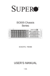
SC743 Chassis Series
SC743TQ-865B-SQ
SC743TQ-865(B)
SC743TQ-R760(B)
SC743S2-R760(B)
SC743S1-R760(B)
SC743T-R760(B)
SC743i-R760(B)
SC743i-665B
SC743T-665B
SC743i-500B
SC743T-500B
SC743i-465B
USER’S MANUAL
1.2d
SC743 Chassis Manual
The information in this User’s Manual has been carefully reviewed and is believed to be accurate.
The vendor assumes no responsibility for any inaccuracies that may be contained in this document,
makes no commitment to update or to keep current the information in this manual, or to notify any
person or organization of the updates. Please Note: For the most up-to-date version of this
manual, please see our web site at www.supermicro.com.
Super Micro Computer, Inc. ("Supermicro") reserves the right to make changes to the product
described in this manual at any time and without notice. This product, including software and
documentation, is the property of Supermicro and/or its licensors, and is supplied only under a
license. Any use or reproduction of this product is not allowed, except as expressly permitted by
the terms of said license.
IN NO EVENT WILL SUPERMICRO BE LIABLE FOR DIRECT, INDIRECT, SPECIAL, INCIDENTAL,
SPECULATIVE OR CONSEQUENTIAL DAMAGES ARISING FROM THE USE OR INABILITY TO
USE THIS PRODUCT OR DOCUMENTATION, EVEN IF ADVISED OF THE POSSIBILITY OF
SUCH DAMAGES. IN PARTICULAR, SUPERMICRO SHALL NOT HAVE LIABILITY FOR ANY
HARDWARE, SOFTWARE, OR DATA STORED OR USED WITH THE PRODUCT, INCLUDING THE
COSTS OF REPAIRING, REPLACING, INTEGRATING, INSTALLING OR RECOVERING SUCH
HARDWARE, SOFTWARE, OR DATA.
Any disputes arising between manufacturer and customer shall be governed by the laws of Santa
Clara County in the State of California, USA. The State of California, County of Santa Clara shall
be the exclusive venue for the resolution of any such disputes. Super Micro's total liability for all
claims will not exceed the price paid for the hardware product.
California Best Management Practices Regulations for Perchlorate Materials: This Perchlorate
warning applies only to products containing CR (Manganese Dioxide) Lithium coin cells. “Perchlorate
Material-special handling may apply. See www.dtsc.ca.gov/hazardouswaste/perchlorate”
WARNING: Handling of lead solder materials used in this
product may expose you to lead, a chemical known to
the State of California to cause birth defects and other
reproductive harm.
Manual Revision 1.2d
Release Date: May 23 2011
Unless you request and receive written permission from Super Micro Computer, Inc., you may not
copy any part of this document.
Information in this document is subject to change without notice. Other products and companies
referred to herein are trademarks or registered trademarks of their respective companies or mark
holders.
Copyright © 2011 by Super Micro Computer, Inc.
All rights reserved.
Printed in the United States of America
ii
Preface
Preface
About This Manual
This manual is written for professional system integrators and PC technicians. It
provides information for the installation and use of the SC743 chassis. Installation
and maintenance should be performed by experienced technicians only.
Supermicro’s SC743 chassis features a unique and highly-optimized design. The
chassis is equipped with a 465, 500, 665, 760 or 865 Watt power supply, and highperformance fans provide ample optimized cooling.
This manual lists compatible parts available when this document was published. Always refer to the our Web site for updates on supported parts and configurations.
iii
SC743 Chassis Manual
Manual Organization
Chapter 1: Introduction
The first chapter provides a checklist of the main components included with this
chassis and describes the main features of the SC743 chassis. This chapter also
includes contact information.
Chapter 2: System Safety
This chapter lists warnings, precautions, and system safety. It recommended that
you thoroughly familiarize yourself installing and servicing this chassis safety precautions.
Chapter 3: Chassis Components
Refer here for details on this chassis model including the fans, airflow shields, and
other components.
Chapter 4: Chassis Setup and Maintenance
Follow the procedures given in this chapter when installing or removing components,
or reconfiguring your chassis.
Chapter 5: Rack Installation
Refer to this chapter for detailed information on chassis rack installation. You should
follow the procedures given in this chapter when installing, removing or reconfiguring
your chassis into a rack environment.
Appendix
Appendix
Appendix
Appendix
Appendix
Appendix
A: Cables, Screws and other Accessories
B: Power Supply Specifications
C: M34S/CSE-M34T Mobile Rack Specifications
D: M35TQ Mobile Rack Specifications
E: SAS-743TQ Backplane Sepcifications
F: SATA-743 Backplane Sepcifications
iv
Preface
Table of Contents
Chapter 1 Introduction
1-1
Overview.......................................................................................................... 1-1
1-2
Shipping List..................................................................................................... 1-1
Part Numbers................................................................................................... 1-1
1-3
Where to get Replacement Components......................................................... 1-2
1-4
Contacting Supermicro..................................................................................... 1-3
1-5
Returning Merchandise for Service................................................................. 1-4
Chapter 2 System Safety
2-1
Overview.......................................................................................................... 2-1
2-2
Warnings and Precautions............................................................................... 2-1
2-3
Preparing for Setup.......................................................................................... 2-1
2-4
Electrical Safety Precautions........................................................................... 2-2
2-5
General Safety Precautions............................................................................. 2-3
2-6
System Safety.................................................................................................. 2-3
Chapter 3 Chassis Components
3-1
Overview.......................................................................................................... 3-1
3-2
Components..................................................................................................... 3-1
Chassis............................................................................................................. 3-1
Mounting to a Rack (Optional)......................................................................... 3-1
Power Supply................................................................................................... 3-1
3-3
Where to get Replacement Components......................................................... 3-2
3-4
Front Control Panel.......................................................................................... 3-2
3-5
Control Panel Buttons...................................................................................... 3-3
3-6
Control Panel LEDs......................................................................................... 3-3
Chapter 4 Chassis Setup and Maintenance
4-1
Overview.......................................................................................................... 4-1
4-2
Removing the Chassis Side and Top Covers.................................................. 4-2
Removing the Side Cover................................................................................ 4-2
Removing the Top Cover................................................................................. 4-3
4-3
Accessing the Hot-Swappable Drive Trays...................................................... 4-4
4-4
Installing Fixed Hard Drives in SC743i Series Chassis Models...................... 4-5
4-5
Installing Hard Drives into the Drive Trays...................................................... 4-6
4-6
Configuring the Storage Module...................................................................... 4-7
Storage Module Options.................................................................................. 4-7
4-7
Removing and Replacing the System Fans.................................................... 4-9
SC743TQ-865B-SQ Cooling System............................................................... 4-9
v
SC743 Chassis Manual
Standard Cooling Systems.............................................................................. 4-9
4-8
Removing the Air Shroud................................................................................4-11
4-9
Installing the Motherboard............................................................................. 4-12
4-10 Installing Expansion Cards............................................................................ 4-14
4-11 Power Supply................................................................................................. 4-16
465, 500, 665 and 865 Watt Power Supplies................................................ 4-16
760 Watt Power Supply................................................................................. 4-18
4-12 Accessing the Interior Space Between the Backplane and the Midplane..... 4-19
4-13 SCSI (Super) GEM Driver Installation Instructions for Windows OS............ 4-20
Chapter 5 Rack Installation
5-1
Overview.......................................................................................................... 5-1
5-2
Unpacking the System..................................................................................... 5-1
5-3
Preparing for Setup.......................................................................................... 5-1
Choosing a Setup Location.............................................................................. 5-1
Rack Precautions............................................................................................. 5-2
General Server Precautions............................................................................. 5-2
Rack Mounting Considerations........................................................................ 5-3
Ambient Operating Temperature................................................................. 5-3
Reduced Airflow.......................................................................................... 5-3
Mechanical Loading.................................................................................... 5-3
Circuit Overloading...................................................................................... 5-3
5-4
Installing the Chassis Rack Mounting Rails..................................................... 5-4
Appendix A Cables, Screws, and other Accessories
A-1
Overview..........................................................................................................A-1
A-2
Cables Included with the SC743 Chassis........................................................A-1
Extending Power Cables..................................................................................A-3
Front Panel to the Motherboard.......................................................................A-3
A-3
Chassis Screws................................................................................................A-4
Appendix B Power Supply Specifications
B-1
Power Supply Options.....................................................................................B-1
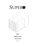
Appendix C CSE-M34S/CSE-M34T Mobile Rack Specifications
Appendix D M35TQ Mobile Rack Specificaitons
Appendix E SAS-743TQ Backplane Specifications
Appendix F SATA-743 Backplane Specifications
vi
Chapter 1: Introduction
Chapter 1
Introduction
1-1 Overview
Supermicro’s SC743 chassis features a unique and highly-optimized design. The
chassis is equipped with a high-efficiency 80%+ low-noise power supply.
1-2 Shipping List
Part Numbers
Please visit the the Supermicro Web site for the latest shiping lists and part numbers
for your particular chassis model at http://www.supermicro.com/
CPU
HDD
I/O Slots
Power
Supply
SC743TQ-865B-SQ
DP Xeon
8x SAS/SATA
7x FF
865W
SC743TQ-865B
DP Xeon
8x SAS/SATA
7x FF
865W
SC743TQ-R760 /
SC743TQ-R760B
DP Xeon
800 FSB
8x SAS/SATA
7x FF
760W
SC743S2-R760 /
SC743S2-R760B
DP Xeon
800 FSB
8x SCA Dual
Channel
7x FF
760W
SC743S1-R760 /
SC743S1-R760B
DP Xeon
800 FSB
8x SCA
7x FF
760W
SC743T-R760 /
SC743T-R760B
UP/DP
Xeon/AMD
8x SATA
7x FF
760W
SC743i-R760 /
SC743i-R760B
UP/DP
Xeon/AMD
8x Fixed
7x FF
760W
SC743T-665B
UP/DP
Xeon/AMD
8x SAS/SATA
7x FF
665W Super
Quiet
SC743i-500B
UP/DP
Xeon/AMD
8x Fixed
7x FF
500W
SC743T-500B
UP/DP
Xeon/AMD
8x SATA
7x FF
500W
SC743i-465 /
SC743i-465B
UP/DP
Xeon/AMD
8x Fixed
7x FF
465W Low
Noise
Model
1-1
SC743 Chassis Manual
1-3 Where to get Replacement Components
Although not frequently, you may need replacement parts for your system. To
ensure the highest level of professional service and technical support, we strongly
recommend purchasing exclusively from our Supermicro Authorized Distributors/
System Integrators/Resellers. A list of Supermicro Authorized Distributors/System
Integrators/Reseller can be found at: http://www.supermicro.com. Click the Where
to Buy link.
1-2
Chapter 1: Introduction
1-4 Contacting Supermicro
Headquarters
Address:
Super Micro Computer, Inc.
980 Rock Ave.
San Jose, CA 95131 U.S.A.
Tel:
+1 (408) 503-8000
Fax:
+1 (408) 503-8008
Email:
[email protected] (General Information)
[email protected] (Technical Support)
Web Site:
www.supermicro.com
Europe
Address:
Super Micro Computer B.V.
Het Sterrenbeeld 28, 5215 ML
's-Hertogenbosch, The Netherlands
Tel:
+31 (0) 73-6400390
Fax:
+31 (0) 73-6416525
Email:
[email protected] (General Information)
[email protected] (Technical Support)
[email protected] (Customer Support)
Asia-Pacific
Address:
Super Micro Computer, Inc.
4F, No. 232-1, Liancheng Rd.
Chung-Ho 235, Taipei County
Taiwan, R.O.C.
Tel:
+886-(2) 8226-3990
Fax:
+886-(2) 8226-3991
Web Site:
www.supermicro.com.tw
Technical Support:
Email:
[email protected]
Tel: 886-2-8226-1900
1-3
SC743 Chassis Manual
1-5 Returning Merchandise for Service
A receipt or copy of your invoice marked with the date of purchase is required before any warranty service will be rendered. You can obtain service by calling your
vendor for a Returned Merchandise Authorization (RMA) number. When returning
to the manufacturer, the RMA number should be prominently displayed on the
outside of the shipping carton, and mailed prepaid or hand-carried. Shipping and
handling charges will be applied for all orders that must be mailed when service
is complete.
For faster service, RMA authorizations may be requested online (http://www.
supermicro.com/support/rma/).
Whenever possible, repack the chassis in the original Supermicro carton, using the
original packaging material. If these are no longer available, be sure to pack the
chassis securely, using packaging material to surround the chassis so that it does
not shift within the carton and become damaged during shipping.
This warranty only covers normal consumer use and does not cover damages incurred in shipping or from failure due to the alteration, misuse, abuse or improper
maintenance of products.
During the warranty period, contact your distributor first for any product problems.
1-4
Chapter 2: System Safety
Chapter 2
System Safety
2-1 Overview
This chapter provides a quick setup checklist to get your chassis up and running.
Following the steps in the order given should enable you to have your chassis set up
and operational within a minimal amount of time. This quick setup assumes that you
are an experienced technician, familiar with common concepts and terminology.
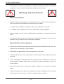
2-2 Warnings and Precautions
You should inspect the box the chassis was shipped in and note if it was damaged
in any way. If the chassis itself shows damage, file a damage claim with carrier
who delivered your system.
Decide on a suitable location for the rack unit that will hold that chassis. It should
be situated in a clean, dust-free area that is well ventilated. Avoid areas where heat,
electrical noise and electromagnetic fields are generated.
The system must be placed near at least one grounded power outlet. When configured, the SC743 chassis includes at least one power supply, "R" model chassis
may include up to three redundant power supplies.
2-3 Preparing for Setup
The SC743 chassis may stand as a tower or bolt directly to a rack. The mounting
screws you will need to install the systems into the rack are included. Please read
this manual in its entirety before you begin the installation procedure.
2-1
SC743 Chassis Manual
2-4 Electrical Safety Precautions
Basic electrical safety precautions should be followed to protect yourself from harm
and the SC743 from damage:
•Be aware of the locations of the power on/off switch on the chassis as well
as the room’s emergency power-off switch, disconnection switch or electrical
outlet. If an electrical accident occurs, you can then quickly remove power from
the system.
•Do not work alone when working with high-voltage components.
•Power should always be disconnected from the system when removing or in-
stalling main system components, such as the serverboard, memory modules
and the DVD-ROM and floppy drives (not necessary for hot-swappable drives).
When disconnecting power, you should first power down the system with the
operating system and then unplug the power cords from all the power supply
modules in the system.
•When working around exposed electrical circuits, another person who is fa-
miliar with the power-off controls should be nearby to switch off the power, if
necessary.
•Use only one hand when working with powered-on electrical equipment. This
is to avoid making a complete circuit, which will cause electrical shock. Use
extreme caution when using metal tools, which can easily damage any electrical
components or circuit boards they come into contact with.
•Do not use mats designed to decrease electrostatic discharge as protection from
electrical shock. Instead, use rubber mats that have been specifically designed
as electrical insulators.
•The power supply power cord must include a grounding plug and must be
plugged into grounded electrical outlets.
•Serverboard battery: CAUTION - There is a danger of explosion if the on-board
battery is installed upside down, which will reverse its polarities. This battery
must be replaced only with the same or an equivalent type recommended by
the manufacturer. Dispose of used batteries according to the manufacturer’s
instructions.
2-2
Chapter 2: System Safety
•Please handle used batteries carefully. Do not damage the battery in any way;
a damaged battery may release hazardous materials into the environment. Do
not discard a used battery in the garbage or a public landfill. Please comply
with the regulations set up by your local hazardous waste management agency
to dispose of your used battery properly.
•DVD-ROM laser: CAUTION - This server may have come equipped with a
DVD-ROM drive. To prevent direct exposure to the laser beam and hazardous
radiation exposure, do not open the enclosure or use the unit in any unconventional way.
2-5 General Safety Precautions
•Keep the area around the chassis clean and free of clutter.
•Place the chassis top cover and any system components that have been re-
moved away from the system or on a table so that they won’t accidentally be
stepped on.
•While working on the system, do not wear loose clothing such as neckties and
unbuttoned shirt sleeves, which can come into contact with electrical circuits or
be pulled into a cooling fan.
•Remove any jewelry or metal objects from your body, which are excellent metal
conductors that can create short circuits and harm you if they come into contact
with printed circuit boards or areas where power is present.
•After accessing the inside of the system, close the system back up and secure
it to the rack unit with the retention screws after ensuring that all connections
have been made.
2-6 System Safety
Electrostatic discharge (ESD) is generated by two objects with different electrical
charges coming into contact with each other. An electrical discharge is created to
neutralize this difference, which can damage electronic components and printed
circuit boards. The following measures are generally sufficient to neutralize this
difference before contact is made to protect your equipment from ESD:
•Do not use mats designed to decrease electrostatic discharge as protection from
electrical shock. Instead, use rubber mats that have been specifically designed
as electrical insulators.
2-3
SC743 Chassis Manual
•Use a grounded wrist strap designed to prevent static discharge.
•Keep all components and printed circuit boards (PCBs) in their antistatic bags
until ready for use.
•Touch a grounded metal object before removing any board from its antistatic
bag.
•Do not let components or PCBs come into contact with your clothing, which may
retain a charge even if you are wearing a wrist strap.
•Handle a board by its edges only; do not touch its components, peripheral chips,
memory modules or contacts.
•When handling chips or modules, avoid touching their pins.
•Put the backplane and peripherals back into their antistatic bags when not in
use.
•For grounding purposes, make sure your computer chassis provides excellent
conductivity between the power supply, the case, the mounting fasteners and
the serverboard.
2-4
Chapter 3: Chassis Components
Chapter 3
Chassis Components
3-1 Overview
This chapter describes the most common components included with your chassis.
Some components listed may not be included or compatible with your particular
chassis model. For more information, see the installation instructions detailed later
in this manual.
3-2 Components
Chassis
The SC743 chassis may include the following options:
•Up to three 5.25" peripheral bays
•Up to eight 3.5" hard drives.
•Up to seven expansion cards
For the latest shipping lists, visit our Web site at: http://www.supermicro.com.
Mounting to a Rack (Optional)
The SC743 can be placed in a rack for secure storage and use. To set up your rack
follow the step-by-step instructions included in this manual.
Power Supply
Each SC743 chassis model includes a high-efficiency power supply with thermal
control fan, rated at 465, 500, 665, 760 or 865 Watts. In the unlikely event your
power supply fails, replacement is simple. The power supply simply needs to be
unscrewed from the chassis and replaced.
3-1
SC743 Chassis Manual
3-3 Where to get Replacement Components
Although not frequently, you may need replacement parts for your system. To
ensure the highest level of professional service and technical support, we strongly
recommend purchasing exclusively from our Supermicro Authorized Distributors/
System Integrators/Resellers. A list of Supermicro Authorized Distributors/System
Integrators/Resellers can be found at: http://www.supermicro.com. Click the Where
to Buy link
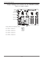
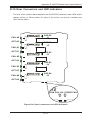
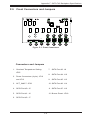
3-4 Front Control Panel
The following diagram defines each component of the front LED panel.
1
2
3
4
5
6
7
8
Figure 3-1: Front Control Panel
1. Power Button
2. System Reset
3. Power Indicator
4. HDD Activity Indicator
5. LAN1 Indicator
6. LAN2 Indicator
7. CPU Temperature/Fan Failure Indicator
8. Power Failure Indicator
9. USB Port
10. USB Port
3-2
9
10
Chapter 3: Chassis Components
3-5 Control Panel Buttons
There are two push-buttons located on the front of the chassis. These are (in order
from left to right) a power on/off button and a reset button.
•Power: The main power switch is used to apply or remove power from the power
supply to the server system. Turning off system power with this button removes
the main power but keeps standby power supplied to the system. Therefore,
you must unplug system before servicing.
•Reset: The reset button is used to reboot the system.
3-6 Control Panel LEDs
The control panel located on the front of the SC743 chassis has six LEDs. These
LEDs provide you with critical information related to different parts of the system.
This section explains what each LED indicates when illuminated and any corrective
action you may need to take.
•Power: The main power switch is used to apply or remove power from the power
supply to the server system. Turning off system power with this button removes
the main power but keeps standby power supplied to the system. Therefore,
you must unplug the system's power cord before servicing.
3-3
SC743 Chassis Manual
•HDD: Indicates IDE channel activity. SAS/SATA drive, SCSI drive, and/or DVDROM drive activity when flashing.
•NIC1: Indicates network activity on GLAN1 when flashing.
•NIC2: Indicates network activity on GLAN2 when flashing.
•Overheat/Fan Fail: When this LED flashes it indicates a fan failure. When
continuously on (not flashing) it indicates an overheat condition, which may be
caused by cables obstructing the airflow in the system or the ambient room
temperature being too warm. Check the routing of the cables and make sure
all fans are present and operating normally. You should also check to make
sure that the chassis covers are installed. Finally, verify that the heatsinks are
installed properly. This LED will remain flashing or on as long as the overheat
condition exists.
3-4
Chapter 3: Chassis Components
!
•Power Fail: Indicates a power failure to the system's power supply units.
3-5
SC743 Chassis Manual
Notes
3-6
Chapter 4: Chassis Setup and Maintenance
Chapter 4
Chassis Setup and Maintenance
4-1 Overview
This chapter covers the steps required to install components and perform maintenance on the chassis. The only tool you will need to install components and perform
maintenance is a Phillips screwdriver. Print this page to use as a reference while
setting up your chassis.
The SC743 i series chassis models do not come equipped with hot-swappable hard
drives. Chassis models in the i series, such as SC743-665, SC743i-500 and SC743i465 must be powered-down prior to removing the hard drives. See the instructions
in this section for details on how to remove and install fixed hard drives.
All other SC743 chassis models include hot-swappable hard drives which may be
replaced without powering down the system. See the instructions in this chapter for
details on how to install and remove hot-swappable hard drives.
!
Review the warnings and precautions listed in
the manual before setting up or servicing this
chassis. These include information in Chapter
2: System Safety and the warning/precautions
listed in the setup instructions.
4-1
!
SC743 Chassis Manual
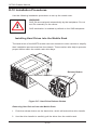
4-2 Removing the Chassis Side and Top Covers
Disconnecting the Chassis from the Power Source
1. Turn off all peripheral devices and turn off the power supply to the SC743.
2. Disconnect the AC power cords from the system.
3. Disconnect all cables and label the cables for easy identification.
!
Warning: Use a grounded wrist strap designed to
prevent static discharge when handling components.
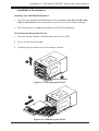
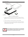
Removing the Side Cover
Removing the Side Cover of the Chassis
1. Disconnect the chassis from any power source as described above.
2. Press the release tab to unlock the cover.
3. The release tab will pop open as shown.
4. Slide the cover back and off of the chassis.
14
12
13
Figure 4-1: Removing the Side Cover
4-2
!
Chapter 4: Chassis Setup and Maintenance
When mounting the SC743 into a rack or changing the power supply, it is necessary
to remove the top cover from the chassis.
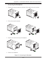
Removing the Top Cover
Removing the Top Cover of the Chassis
1. Disconnect the chassis from any power source.
2. Press the release tab at the back of the top cover.
3. Slide the back cover off the chassis.
Release Tab
12
13
Figure 4-2: Removing the Top Cover
4-3
SC743 Chassis Manual
4-3 Accessing the Hot-Swappable Drive Carriers
Hot-swappable drives may be removed and installed in the chassis without powering-down the system and without opening the chassis cover.
Accessing and Removing Hard Drive Carriers
1. Unlock and open the drive carrier door as shown.
2. Press the release tab located on the drive carrier. This will release the drive
carrier from its locked position.
3. Lift up the drive carrier handle.
4. Pull the drive carrier out from the chassis using the handle.
Installing Hard Drive Carriers
1. Gently push the hard drive carrier all the way into the hard drive bay.
2. Push in the drive carrier handle until it clicks into the locked position.
(Note: The orientation of the picture shown below is for rack mount systems.)
3
2
4
1
Figure 4-3: Removing Hard Drive Carrier
4-4
Chapter 4: Chassis Setup and Maintenance
4-4 Installing Hard Drives into the Drive Carriers
Installing Hard Drives
1. Remove the screws from the hard drive carrier and set them aside for later
use.
2. Remove the dummy drive from the hard drive carrier.
3. Mount a hard drive into the hard drive carrier
4. Replace the screws which were set aside earlier.
5. Install the hard drive into the chassis.
6. Push down the release tab over the newly installed hard drive.
7. Close the hard drive carrier door.
12
13
Installing the Hard Drive
Removing the Dummy Drive
Figure 4-5: Hard Drive Carrier
!
Warning! Enterprise level hard disk drives are recommended for
use in Supermicro chassis and servers. For information on recommended HDDs, visit the Supermicro Web site at http://www.
supermicro.com/products/nfo/files/storage/SAS-1-CompList110909.pdf
4-5
SC743 Chassis Manual
4-5 Installing Fixed Hard Drives in SC743i Series
Chassis Models
The SC743i series chassis features dual fixed storage modules. The system must
be powered-down and disconnected from any power source before installing or
removing hard drives.
Disconnecting the Chassis from the Power Source
1. Turn off all peripheral devices and turn off the power supply to the SC743.
2. Disconnect the AC power cord from the system.
3. Disconnect all cables and label the cables for easy identification.
4. Open the chassis side cover as described in section 4-2.
5. Disconnect the wiring which runs to either the motherboard or the expansion
card of the motherboard, depending upon your chassis model.
6. Unlock and open the door on the front of the chassis.
7. Insert the 3.5" drives into the fixed hard drive bays.
8. Secure the 3.5" drives into the fixed hard drive bays with the screws provided.
9. Close and lock the front cover.
10. Reconnect power to the system.
4-6
Chapter 4: Chassis Setup and Maintenance
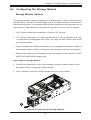
4-6 Configuring the Storage Module
Storage Module Options
The storage module can be configured to accommodate a variety of data storage
devices such as CD, IDE, DVD and floppy drives. The chassis may be rotated from a
vertical tower position, to a horizontal rack mounting position to accommodate use of
these devices. The following configurations may be used in the SC743 chassis:
•5.25" Drives: Install any combination of three 5.25" devices.
•3.5" Drives: Install three 3.5" fixed hard drives in a 5.25" peripheral drive bay,
or install five hot-swappable hard drives by using an M35 mobile rack inside
the storage module.
•Tower Configuration: Rotate the chassis into an upright tower position. Remove
the storage module, rotate it 90 degrees and reinstall it back into the chassis.
•Mobile Rack: Remove the storage module and replace it with either the CSEM35TQ or CSSE-M35S mobile rack.
Removing the Storage Module
1. Locate the release tab on top of the storage module as shown below. Press
the release tab to unlock the storage module.
2. Once unlocked, push the module forward and out of the chassis.
1
2
Figure 4-6: Removing the Storage Module
4-7
SC743 Chassis Manual
Configuring the Storage Module for 5.25" Devices
1. Remove the 5.25” drive carriers from the storage module.
2. Remove the screws and drive carrier brackets from the drive carriers.
3. Install the 5.25” devices into the storage module.
4. Replace the module back into the chassis.
5. Ensure that the storage module is securely locked into position.
Figure 4-7: Installing 5.25" Devices into the Storage Module
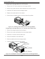
Configuring the Storage Module for 3.5" Devices with a Mobile Rack
1. Remove the storage module from the chassis.
2. Remove the screws and brackets from the storage module.
3. Install the 3.5” devices into the mobile rack.
4. Secure the brackets to the mobile rack.
5. Slide the mobile rack into the storage module
6. Slide the storage module into the chassis.
Storage Module
Mobile Rack
Bracket
3.5" Devices
Figure 4-8: Installing 3.5" Devices into Mobile Rack and Storage Module
4-8
Chapter 4: Chassis Setup and Maintenance
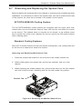
4-7 Removing and Replacing the System Fans
Before installing the motherboard in the chassis or accessing the motherboard after
installation, it is necessary to remove the system fans. One set is located at the rear
of the chassis, the other set is located in the middle of the chassis.
SC743TQ-865B-SQ Cooling System
The SC743TQ-865B-SQ model chassis are equipped with two super quiet midchassis fans, two non-functional "dummy" fans, one rear fan, and does not require
an air shroud. This chassis does not require an air shroud. In the unlikely event
that a system fan needs to be replaced, be sure to specify the SQ model number
when ordering parts.
Standard Cooling Systems
Most SC743 model chassis include mid-chassis cooling fans, rear cooling fans and
an air shroud to channel air within the chassis.
Removing and Replacing Mid-chassis Fans
1. Press the release tab located on the left side of the middle chassis fan.
2. While holding down the release tab, pull the fan upwards, and out of the
chassis.
3. When replacing the middle chassis fan, push the fan back into the fan module
slot until a click is heard, indicating that the fan has locked into position.
Release Tab
Figure 4-9: Removing the Middle Chassis Fans
4-9
SC743 Chassis Manual
Removing Rear Chassis Fans
1. Locate the release tab on the top of the chassis fan, at the rear of the chassis. Push the release tab down to unlock the fan.
2. Once the fan is unlocked, tip it forward and out of the chassis.
3. When replacing the rear chassis fan, push the fan back into the fan module
until a click is heard, indicating that the fan has locked into position.
1
2
Figure 4-10: Removing Rear Chassis Fans
4-10
Chapter 4: Chassis Setup and Maintenance
4-8 Removing the Air Shroud
Before installing the motherboard in the chassis or accessing the motherboard
after installation, it is necessary to remove the air shroud between the two sets of
system fans.
SC743TQ-865B-SQ model chassis are equipped with a specialized air shroud to
accommodate the super quiet front and rear fans. Be sure to specify the air shroud
model number MCP-310-74301-ON upon arrival, in the unlikely event that the air
shroud needs to be replaced.
Removing the Air Shroud
1. Press the release tab on the middle chassis bracket until a click is heard.
2. Press the release tab on the back of the rear chassis fans.
3. Lift the air shroud upward and out of the chassis.
1
2
3
Figure 4-11: Removing the Air Shroud
4-11
SC743 Chassis Manual
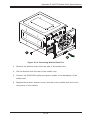
4-9 Installing the Motherboard
Prior to Installing the Motherboard
Before the motherboard can be installed or removed, the air shroud must be removed, as directed in sections 4-8. The following information is for reference only,
the motherboard is not included with the SC743 chassis.
Identify the locations of the following components:
•Processor(s)
•Mounting holes
•Retention brackets
•Type A (6-32) screws (included in the chassis accessory kit)
Obtain the following parts for the motherboard being used. These should be included
with the motherboard. (Refer to the motherboard documentation for details)
•I/O shield
•Chassis standoffs
•Heatsink retention brackets
Motherboard Installation
Installing the Motherboard
1. Disconnect the power supply.
2. Lay the chassis on a flat surface.
3. Compare the mounting holes in the chassis to those on the motherboard.
4. Add and remove standoffs as needed.
5. Install the I/O shield as directed by the motherboard documentation.
4-12
Chapter 4: Chassis Setup and Maintenance
6. Secure the heatsink to the motherboard as directed by the motherboard
documentation.
7. Secure the motherboard to the chassis using Type A screws, which are included in the chassis accessory kit. Do not exceed eight pounds of torque per
square inch when tightening down the motherboard.
8. Replace the middle and rear system fans as directed in section 4-6.
9. Replace the air shroud as directed in section 4-7.
Figure 4-12: Installing the Motherboard
!
Warning: The system fans, air shroud and chassis cover must be installed prior to operating the
system. Out-of-warranty damage may result if the
system is operated without proper cooling protection in place.
4-13
!
SC743 Chassis Manual
4-10 Installing Expansion Cards
After installing the motherboard, expansion cards may be installed into the chassis.
Installing Expansion Cards
1. Locate the release tab on the top of the PCI slot bracket
2. Gently apply pressure on the middle of the release tab to unlock the bracket
as shown.
1
2
Figure 4-13: Installing Expansion Cards
4-14
Chapter 4: Chassis Setup and Maintenance
3. Once the bracket is unlocked, pull the release tab upward and remove the
bracket from the chassis.
4. Gently slide the expansion card bracket into the PCI slot until it clicks into
place.
4-15
SC743 Chassis Manual
4-11 Power Supply
The SC743 chassis includes a power supply rated at either 465, 500, 665, 760 or
865 Watts. In the unlikely event that you need to replace the power supply, simply
follow the directions for your specific power supply below.
!
Warning: Always unplug the power cord before removing the power supply.
Warning: Do not open the casing of the power supply.
Power supplies can only be serviced by a qualified
manufacturer's technician.
!
465, 500, 665 and 865 Watt Power Supplies
The 465, 500 665 and 865 Watt power supplies offer different features, but are
designed to be installed and removed in the same way.
Installing the Power Supply
1. Unplug the power cord from the power supply.
2. Remove both the side and top covers from the chassis as described in section 4-2 of this manual.
1
Figure 4-14: Installing the 465, 500, 665 or 865 Watt Power Supply
4-16
Chapter 4: Chassis Setup and Maintenance
3
Remove
Screws
14
Figure 4-15: Removing the Interior Chassis Screws on the Power Supply
3. Using a Phillips head screwdriver, remove the five screws securing the power
supply to the chassis as shown above, and set them aside for later use.
4. Carefully lift the power supply up and out of the chassis.
5. Install the replacement power supply in the chassis.
6. Replace the screws which were set aside previously.
7. Replace any other components in the chassis that have been removed and
replace the chassis cover before replacing the power cord and powering up
the system.
4-17
SC743 Chassis Manual
760 Watt Power Supply
The 760 Watt power supply is a triple redundant power supply with a different configuration than that of the 465, 500, 665 and 865 Watt power supplies.
Installing the Power Supply
1. Unplug the AC power cord from the power supply.
2. Push the release tab on the left side of each power supply to release it from
the locked position.
3. Once released from the locked position, pull the power supply outward, using
the handle provided.
4. Install the replacement power supply in the chassis.
5. Replace any other components in the chassis that have been removed and
replace the chassis cover before replacing the power cord and powering up
the system.
Upper Release Tab
Upper Power Cord
Middle Release Tab
Middle Power Cord
Lower Release Tab
Lower Power Cord
Figure 4-16: Installing the 760 Watt Power Supply
4-18
Chapter 4: Chassis Setup and Maintenance
4-12 Accessing the Interior Space Between the
Backplane and the Midplane
For easy access to the interior space between the backplane and the midplane,
follow the instructions below before installing components or cables into this area.
Accessing the Interior Space
1. Remove the two screws as shown below and set them aside for future use.
2. Remove the three screws on the bottom of the bracket between the back
plane and the mideplane.
3. Use a standard screwdriver to gently press the release tabs to release the
midplane
4. Pull the midplane forward approximately 35 degrees, as shown in the illustration below. The interior space is now accessible.
1
4
1
2
3
3
Figure 4-17: Accessing the Interior Backplane/Midplane Space
4-19
SC743 Chassis Manual
4-13 SCSI (Super) GEM Driver Installation Instructions
for Windows OS
Note: This driver is not necessary for other operating systems. If you have two SCA
backplanes, you will need to install the driver twice. The driver is located on the
Super Micro motherboard driver CD or may be downloaded from the Supermicro
ftp site: ftp://ftp.supermicro.com/driver/Qlogic/
Follow the procedure below to install this driver onto your system.
Installing the Driver
1. Right click on the My Computer icon and choose Properties.
2. Select the Hardware tab and click on Device Manager.
3. Open System Devices or browse to the location of GEM318.
4. Right click on this device and select Properties.
5. Click on Driver tab and select Update Driver.
6. Click the Next button twice.
7. Uncheck both options for Floppy Disk Drives and CD-ROM Drives.
8. Select Specify a Location and click the Next button.
9. Click on the Browse button and select the drive containing the Supermicro
Setup CD.
10. Select the Qlogic folder and click on the Open button.
11. System will automatically detect GEM318 and install the drive from this point
on.
Or, use the following procedure:
4-20
Chapter 4: Chassis Setup and Maintenance
Installing the Driver (Alternative Procedure)
1. Right click the “My Computer” icon on your desktop and choose Properties.
2. Click on the Hardware tab and select Device Manager to bring up the list of
system devices.
3. You may see one or two yellow question marks (?) that read QLogic GEM354
or GEM318 SCSI Processor Device. Right click on these, and select uninstall.
If two such question marks are present, uninstall both.
4. Select the Action tab and click on Scan for Hardware Changes. The Hardware Wizard program should start up. Click the Next button.
5. At the first prompt, select Display a list of known device drivers for the
device so that I can choose a specific driver and click the Next button.
6. Select Other Devices and click Next.
7. Select Have Disk, specify your floppy drive location in the options box, and
click Next.
8. Select Enclosure Services Device and click Next.
9. Ignore the warning prompt by clicking Yes.
4-21
SC743 Chassis Manual
Notes
4-22
Chapter 5: Rack Installation
Chapter 5
Rack Installation
5-1 Overview
This chapter provides instructions on installing the chassis into a rack. Following
these steps in the order given should enable you to have the system installed in a
minimal amount of time.
5-2 Unpacking the System
You should inspect the box the chassis was shipped in, and note if it was damaged
in any way. If the chassis itself shows damage, you should file a damage claim with
the carrier who delivered it.
Decide on a suitable location for the rack unit that will hold your chassis. It should
be situated in a clean, dust-free area that is well ventilated. Avoid areas where
heat, electrical noise and electromagnetic fields are generated. You will also need
it placed near a grounded power outlet. Be sure to read the Rack and Server Precautions in the next section.
5-3 Preparing for Setup
The box your chassis was shipped in should include four mounting screws, which
you will need if you intend to install the system into a rack. Read this section in
its entirety before you begin the installation procedure outlined in the sections that
follow.
Choosing a Setup Location
•Leave enough clearance in front of the rack to enable you to open the front
door completely (~25 inches).
•Leave approximately 30 inches of clearance in back of the rack to allow for
sufficient airflow and ease in servicing.
5-1
SC743 Chassis Manual
•This product is only to be installed in a Restricted Access Location (dedicated
equipment rooms, service closets and similar environments).
!
Warnings and Precautions!
!
Rack Precautions
•Ensure that the leveling jacks on the bottom of the rack are fully extended to
the floor with the full weight of the rack resting on them.
•In single rack installation, stabilizers should be attached to the rack.
•In multiple rack installations, the racks should be coupled together.
•Always make sure the rack is stable before extending a component from the
rack.
•You should extend only one component at a time. Extending two or more simultaneously may cause the rack to become unstable.
General Server Precautions
•Review the electrical and general safety precautions that came with the components you are adding to your chassis.
•Determine the placement of each component in the rack.
•Install the heaviest server components on the bottom of the rack first, and then
work up.
•Use a regulating, uninterruptible power supply (UPS) to protect the server from
power surges, voltage spikes and to keep your system operating in case of a
power failure.
•Allow
the hard drives and power supply modules to cool before touching
them.
•Always keep the rack's front door, all panels and all components on the servers
closed when not servicing, in order to maintain proper cooling.
5-2
Chapter 5: Rack Installation
Rack Mounting Considerations
Ambient Operating Temperature
If installed in a closed or multi-unit rack assembly, the ambient operating temperature of the rack environment may be greater than the ambient temperature of the
room. Therefore, consideration should be given to installing the equipment in an
environment compatible with the manufacturer’s maximum rated ambient temperature (TMRA).
Reduced Airflow
Equipment should be mounted into a rack so that the amount of airflow required
for safe operation is not compromised.
Mechanical Loading
Equipment should be mounted into a rack so that a hazardous condition does not
arise due to uneven mechanical loading.
Circuit Overloading
Consideration should be given to the connection of the equipment to the power
supply circuitry and the effect that any possible overloading of circuits might have
on overcurrent protection and power supply wiring. Appropriate consideration of
equipment nameplate ratings should be used when addressing this concern.
Reliable Ground
A reliable ground must be maintained at all times. To ensure this, the rack itself
should be grounded. Particular attention should be given to power supply connections other than the direct connections to the branch circuit (for example, the use
of power strips, and other devices).
5-3
SC743 Chassis Manual
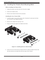
5-4 Installing the Chassis Rack Mounting Rails
Before Installing the Chassis Rails
1. Unplug the power cord from the from the power supply.
2. Secure the chassis cover.
3. Remove all external devices and connectors.
Installing the Inner Chassis Rails
1. Locate the pair of inner rails and two sets of screws (6 screws per set) that
are included in the shipping package.
2. Remove the chassis feet and top cover.
3. Align the inner rails against the chassis as shown.
12
14
13
14
Figure 5-1: Installing the Inner Chassis Rails
4. Secure the inner rails onto the chassis with the screws provided. Ensure that
the inner rails are mounted flush with the edge of the chassis.
5-4
Chapter 5: Rack Installation
Installing the Outer Chassis Rails
1. Locate the two pairs of outer rails. Each pair consists of one middle rail, one
end bracket and one end rail as shown.
Middle Rail
End Rail
End Bracket
Figure 5-2: Assembling the Outer Chassis Rails
2. Insert the end bracket and the end rail onto the middle rail and secure them
with the screws as shown.
3. Install a set of outer rail assemblies to each side of the rack and secure them
with the screws provided.
4. Check that both sets of inner rails are securely attached to the chassis.
5. Check that both sets of outer rails are securely attached to the rack.
6. Insert the inner rails on the chassis, into the outer rails on the rack.
7. Gently slide the chassis into position within the rack.
5-5
SC743 Chassis Manual
Outer Rail
Assemblies
Inner Rails
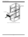
Figure 5-3: Mounting the Chassis into a Rack
5-6
Appendix A: Chassis Cables
Appendix A
Cables, Screws,
and other Accessories
A-1 Overview
This appendix lists supported cables for your chassis system. It only includes the
most commonly used components and configurations. For more compatible cables,
refer to the manufacturer of the motherboard you are using and to the Supermicro
Web site at: www.supermicro.com.
A-2 Cables Included with the SC743 Chassis
SC743S1 Series (SCSI)
Part #
Type
Length
Description
CBL-033L-U320
Cable
9"
Two-drop SCSI ultra 320 cable
CBL-0087
Cable
20"
Round 16-pin to 16-pin front panel
ribbon cable
CBL-0084
Cable
6"
Split converter cable
CBL-0063L
Cable
20"
SCSI cable
CBL-0062L
Cable
7.9"
12V 8-pin to 8-pin power connector
extension cable
CBL-0209L
Cable
8.26"
(210mm)
4-pin to 3-pin fan power cable
SC743S2 Series (SCSI)
Type
Length
CBL-033L-U320
Part #
Cable
9"
Two-drop SCSI ultra 320 cable
CBL-0087
Cable
20"
Round 16-pin to 16-pin front panel
ribbon cable
CBL-0084
Cable
6"
Split converter cable
CBL-0063L
Cable
20"
SCSI cable
CBL-0062L
Cable
7.9"
12V8-pin to 8-pin power connector
extension cable
CBL-0209L
Cable
8.26"
(210mm)
A-1
Description
4-pin to 3-pin fan power cable
SC743 Chassis Manual
SC743T Series (SAS/SATA)
Part #
Type
Length
Description
CBL-0044L
Cable
2'
CBL-0087
Cable
20"
Round 16-pin to 16-pin front panel
ribbon cable
CBL-0084
Cable
6"
Split converter cable
CBL-0062L
Cable
7.9"
CBL-0209L;
Cable
8.26"
(210mm)
SATA cable (Amphenol)
12V 8-pin to 8-pin power connector
extension cable
4-pin to 3-pin fan power cable
Note: The SC743T-665 includes the first three cables above only, plus CBL-0216L
a 200mm, 4-pin to 4-pin middle fan power extension cable
SC743TQ Series (SATA/SCSI)
Type
Length
CBL-0044L
Part #
Cable
2'
Description
CBL-0087
Cable
20"
Round 16-pin to 16-pin front panel
ribbon cable
CBL-0084
Cable
6"
Split converter cable
CBL-0157L
Cable
15.8"
CBL-0216L
Cable
8.26"
(210mm)
SATA cable (Amphenol)
8-pin to 8-pin ribbon cable for
SGPIO (supports up to 4 drives)
4-pin to 4-pin fan power cable
SC743i Series
Part #
Type
Length
CBL-0087
Cable
20"
Round 16-pin to 16-pin front panel
ribbon cable
CBL-0084
Cable
6"
Split converter cable
CBL-0209L
Cable
8.26"
(210mm)
4-pin to 3-pin fan power cable
CBL-0216L
Cable
8.26"
(210mm)
4-pin to 4-pin fan power cable
(optional)
A-2
Description
Appendix A: Chassis Cables
Extending Power Cables
Although Supermicro chassis are designed with to be efficient and cost-effective,
some compatible motherboards have power connectors located in different areas.
To use these motherboards you may have to extend the power cables to the mother
boards. To do this, use the following chart as a guide.
Power Cable Extenders
Number of Pins
Cable Part #
Length
24-pin
CBL-0042
7.9”(20 cm)
20-pin
CBL-0059
7.9”(20 cm)
8-pin
CBL-0062
7.9”(20 cm)
4-pin
CBL-0060
7.9”(20 cm)
Front Panel to the Motherboard
The SC743 chassis includes a cable to connect the chassis front panel to the
motherboard. If your motherboard uses a different connector, use the following
chart to find a compatible cable.
Front Panel to Motherboard Cable (Ribbon Cable)
Number of Pins
(Front Panel)
Number of Pins
(Motherboard
Cable Part #
16-pin
16-pin
CBL-0049
16-pin
20-pin
CBL-0048
20-pin
20-pin
CBL-0047
16-pin
various*
CBL-0068
20-pin
various*
CBL-0067
* Split cables: Use these cable if your motherboard requires several different connections from the front panel.
A-3
SC743 Chassis Manual
A-3 Chassis Screws
The accessory box includes all the screws needed to set up your chassis. This
section lists and describes the most common screws used. Your chassis may not
require all the parts listed.
M/B
HARD DRIVE
Flat head
6-32 x 5 mm
[0.197]
Pan head
6-32 x 5 mm
[0.197]
DVD-ROM, CD-ROM, and FLOPPY DRIVE
Pan head
6-32 x 5 mm
[0.197]
Flat head
6-32 x 5 mm
[0.197]
Round head
M3 x 5 mm
[0.197]
Round head
M2.6 x 5 mm
[0.197]
RAIL
Flat head
M4 x 4 mm
[0.157]
Round head
M4 x 4 mm
[0.157]
Flat head
M5 x 12 mm[0.472]
Washer for M5
M/B STANDOFFS
M/B standoff
6-32 to 6-32
M/B (CPU)
standoff
M5 to 6-32
Thumb screw
6-32 x 5 mm
[0.197]
A-4
1/U M/B standoff
6-32 x 5 mm
[0.197]
Appendix B: Power Supply Specifications
Appendix B
Power Supply Specifications
B-1 Power Supply Options
This appendix lists power supply specifications for your chassis system.
465W
MFR Part #
PWS-465-PQ
Rated AC Voltage
100 - 240V
60 - 50Hz
6 - 3 Amp
+5V standby 3 Amp
+12V
35 Amp
+5V
20 Amp
+3.3V
15 Amp
-12V
0.5 Amp
500W
MFR Part #
PWS-502-PQ
Rated AC Voltage
100 - 240V
50 - 60Hz
12 - 6 Amp
+5V standby 6.5 Amp
+12V
69 Amp
+5V
30 Amp
+3.3V
-12V
305 Amp
1 Amp
B-1
SC743 Chassis Manual
665W
MFR Part #
PWS-665-PQ
Rated AC Voltage
100 - 240V
50 - 60Hz
10- 5 Amp
+5V standby 6 Amp
+12V
54.0 Amp
+5V
30.0 Amp
+3.3V
24 Amp
-12V
0.5 Amp
R760W
MFR Part #
PWS-0056
Rated AC Voltage
100 - 240V
50 - 60Hz
14 - 8 Amp
+5V standby 3.5 Amp
+12V
50.0 Amp
+5V
36.0 Amp
+3.3V
36.0 Amp
-12V
1.0 Amp
865W
MFR Part #
PWS-865-PQ
Rated AC Voltage
100 - 240V
50 - 60Hz
12- 6 Amp
+5V standby 6.5 Amp
+12V
70.0 Amp
+5V
30.0 Amp
+3.3V
30.0 Amp
-12V
1.0 Amp
B-2
Apppendix C: CSE-M34S/CSE-M34T Mobile Rack Specifications
Appendix C
CSE-M34S/CSE-M34T Mobile Rack Specifications
C-1 Overview
This manual is written for system integrators, PC technicians and
knowledgeable PC users. It provides detailed information for the installation and
use of the CSE-M34S/CSE-M34T mobile rack.
The Supermicro CSE-M34S/CSE-M34T mobile rack offers cutting edge technolgy
with greater flexibility. The CSE-M34T supports 4 Serial ATA hot-swappagle hard
drives. These hard drive yield an unparalleled storage capacity without compromising productivity, by eliminating possible system downtime. The CSE-M34S also accommodates four SCSI SCA 320/160 hard drives, providing configuration flexibility
and maximum data integrity.
If your system is running on a Windows operating system, refer to section 4-13
of this manual for instructions on installing the appropriate drivers required by the
backplane of the CSE-M34S or CSE-M34T mobile rack.
C-2 Product Features
Occupancy
•
Three 5.25" drive bays
Capacity
•
Five 1" SCA Ultra 320/160 hard drives with SAF-TE
built-in (CSE-M35S only)
Five 1" host receptacle connectors, SATA hot-swappable hard drives (CSE-M35T-1 only)
•
Cooling Subsystem
Monitoring
•
•
•
•
•
One 9cm exhaust fan
Fan fail detection LED and alarm
Overheat LED indication
Drive fail alarm indication (CSE-M35S only)
Built-in termination (CSE-M35S only)
Dimension (WxHxD)
•
146mm x 129mm x 245mm (5.7 in x 5.0 in x 9.5 in)
Weight
•
Net: 5.9lb (2.9 kg), Gross: 7.5lb (3.7 kg)
Chassis supported: SC762, SC830, SC942, and SC743.
C-1
SC743 Chassis Manual
C-3 Packing List
The CSE-M34S/CSE-M34T mobile rack provides the following:
•CSE-M34S/CSE-M34T mobile rack
•90 mm exhaust fan
•Drive carrier four CSE-PT10 (-beige only)
•Six counts of 6-32 hex washer head screws
•Eight counts of M3 washer head screws
•Eighteen counts of pan head screws
For CSE-M34T only
•Serial ATA backplane (CSESATA-M34)
•Four Serial ATA cables (CBL-0044)
•Serial ATA LED cable (CBL-0057)
•SCSI cable (CBL-027-U320)
•SCSI backplane (CSESCA-002)
Supported Operating Systems
This mobile rack supports the following operating systems:
•Windows 2000, Windows XP, and Windows 2003
•Linux: Red Hat and SuSE
C-2
Apppendix C: CSE-M34S/CSE-M34T Mobile Rack Specifications
Additional Information
The CSE-M34S/CSE-M34T mobile rack was designed for use in certain chassis
and servers or as a stand alone unit. Use the chassis or server manual for installation instructions. Use the instructions listed in this manual to use the mobile rack
independent of a chassis.
The pictures or graphics shown in this user’s guide were based upon the latest PCB
revision available at the time of the publishing of this manual. The CSE-M34S/CSEM34T mobile rack may or may not look exactly the same as the graphics shown in
this manual. The availability of SAS-devices supported depends on the readiness
of firmware and hardware support.
C-3
SC743 Chassis Manual
C-4 Front Connectors and Jumpers
JP24
JP14 JP25
JP21
JP18
Figure C-1. Mobile Rack Backplane (Front)
Jumper Settings
Jumper settings for the CSE-M34S (SCSI)
Jumper
Description
Setting
JP14
Delay start
Closed: Enable
Open Disable (default)
JP18
Bumper Reset
Closed: Enable
Open Disable (default)
JP21
SCSI Termination
Closed: Enable
Open Disable (default)
JP24
SCSI ID Selection
1-2: SCSI IDs: 0, 1, 2, 3, 4, (default)
2-3: SCSI IDs: 9,10,11,12,13
C-4
Apppendix C: CSE-M34S/CSE-M34T Mobile Rack Specifications
JP25
Overheat Temperature
Open: 45 degrees Celcius
1-2: 50 degrees Celcius (Default)
2-3: 55 degrees Celcius
JP26
Common Act#1-Act#4
Connect this header to CBL-0057 (SATA LED
Cable)
JP27
Common Act In-Act#1
Closed: Enable
Open: Disable (default)
JP28
Fan Sense
1-2: Enabled (if a fan is not present, the alarm will
sound) (default)
2-3: Disabled
JP29
Common Act In-Act#2
Closed: Enable
Open: Disable (default)
JP30
Common Act In-Act#3
Closed: Enable
Open: Disable (default)
JP31
Common Act In-Act#1
Closed: Enable
Open: Disable (default)
JP32
Common Act Out
Closed: Enable
Open: Disable (default)
C-5
SC743 Chassis Manual
Jumper Settings and Locations for the CSE-M35T (SATA)
Figure C-2: Jumper Locations
JP25
JP18
Channel #1
Channel #2
Channel #3
Channel #4
JP28
Activity LEDs Pin Definitions JP26
ACT1
Act. LED1 = Channel 1
JP26
ACT2
ACT3
ACT4
COM
Act. LED2 = Channel 2
Act. LED3 = Channel 3
Act. LED4 = Channel 4
C-6
Key
Apppendix C: CSE-M34S/CSE-M34T Mobile Rack Specifications
Installation Procedures
Installing the CSE-M35S Backplane
1. SCSI IDs are assigned automatically by the backplane. Do not set IDs manually on the drives. See the previous section for SCSI ID jumper settings.
2. SCSI termination is enabled by default on the SCSI backplane.
Accessing Hot-Swappable Drives
1. Push the release button located beside each drive's LED.
2. Lift up on the drive's handle.
3. Carefully pull the drives out of the storage module.
2
1
Release Buttons
Figure C-3: Releasing the Drives
3
Figure C-4: Removing the Drives
C-7
SC743 Chassis Manual
Installing a Drive into the Drive Tray
1. Mount the drive in the drive tray.
2. Secure it into the drive tray as shown with the screws provided.
Figure C-5: Installing the Drive into the Drive Tray
!
Warning! Enterprise level hard disk drives are recommended for
use in Supermicro chassis and servers. For information on recommended HDDs, visit the Supermicro Web site at http://www.
supermicro.com/products/nfo/files/storage/SAS-1-CompList110909.pdf
C-8
Apppendix C: CSE-M34S/CSE-M34T Mobile Rack Specifications
Accessing the Backplane
1. Remove the screws located on the back of the mobile rack unit as shown
1
1
2. Pull out the rear fan bracket.
2
2
3. Remove the screws securing the backplane.
3
4
4. Remove the backplane.
Figure C-6: Accessing the Backplane
C-9
SC743 Chassis Manual
Notes
C-10
Appendix D: M35TQ Mobile Rack Specifications
Appendix D
M35TQ Mobile Rack Specificaitons
D-1 Overview
This manual is written for system integrators, PC technicians and knowledgeable PC
users who intend to integrate Supermicro's intelligent, highly expandable and costeffective mobile rack solutions into their systems. It provides the user with detailed
information for the installation and use of the M35TQ mobile rack.
The Supermicro M35TQ mobile rack supports SAS or SATA hard drives, and can
accomodate up to five 3.5" hard drives or three 5.25" hard drives. The M35TQ
showcases today's most advanced technological innovations in modular connectivity and data transferability, laying the foundation for reliable, effective and scalable
solutions for tomorrow's data communications industry.
D-2 Product Features
The M35TQ mobile rack includes the following features:
•Supports SAS or SATA
•Supports five 3.5" hot-swappable HDDs or three 5.25" HDDs
System Monitoring
•Fan failure LED
•Overheat LED indicatior
•Drive activity indicatior
D-1
SC743 Chassis Manual
D-3 An Important Note to the User
The pictures or graphics shown in this User's Guide were based upon the latest
PCB revision available at the time of the publishing of this manual. The M35TQ
mobile rack you've received may or may not look exactly the same as the graphics
shown in this manual.
D-4 ESD Safety Guidelines
Electrostatic Discharge (ESD) can damage electronic components. To prevent damage to your system, it is important to handle it very carefully. The following measures
are generally sufficient to protect your equipment from ESD.
•Use a grounded wrist strap designed to prevent static discharge.
•Touch a grounded metal object before removing a component from the antistatic
bag.
•Handle the backplane by its edges only; do not touch its components, peripheral
chips, memory modules or gold contacts.
•When handling chips or modules, avoid touching their pins.
•Put the backplane and peripherals back into their antistatic bags when not in
use.
D-5 General Safety Guidelines
•Always disconnect power cables before installing or removing any components
from the computer, including the mobile rack.
•Disconnect the power cable before installing or removing any cables from the
mobile rack.
D-2
Appendix D: M35TQ Mobile Rack Specifications
•Make sure that the mobile rack is securely and properly installed on the motherboard to prevent damage to the system due to power shortage.
D-6 Introduction to the SAS-M35TQ Backplane
The M35TQ mobile rack contains a SAS-M35TQ backplane. The SAS-M35TQ
backplane has been designed to utilize the most up-to-date technology available,
providing your system with reliable, high-quality performance.
This manual reflects SAS-M35TQ Revision 1.01, the most current release available
at the time of publication. Always refer to the Supermicro Web site at www.supermicro.com for the latest updates, compatible parts and supported configurations.
D-3
SC743 Chassis Manual
D-7 Front Connectors and Jumpers
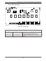
1
S UPER
13
12
R
1
SASM35TQ
18
15
REV 1.01
14
17
111
12
1
13
1
14
1
15
1
16
19
10
1
Figure D-1: Front Connectors
Front Connectors
1. 4-pin Power Connectors: JP10
and JP13
8. Upgrade: JP46
9. ACT IN: JP26
2. MG9072 Chip
10. Fan Connector: JP22
3. JTAG Connector: JP47
11. SAS Port #0: J5
4. I2C Connector #1: JP44
12. SAS Port #1: J6
5. I2C Connector #2: JP45
13. SAS Port #2: J7
6. Sideband Connector #1: JP51
14. SAS Port #3: J8
7. Sideband Connector #2: JP52
15. SAS Port #4: J10
D-4
Appendix D: M35TQ Mobile Rack Specifications
D-8 Front Connectors and Pin Definitions
1. Mobile Rack Main Power Connectors
The 4-pin power connectors, designated JP10
and JP13, provide power to the mobile rack.
See the table on the right for pin definitions.
Mobile rack
Main Power
4-Pin Connector
Pin#
Definition
1
+12V
2 and 3
4
Ground
+5V
2. MG9072 Chip
The MG9072 is an enclosure management
chip that supports the SES-2 controller and
SES-2 protocols.
3. JTAG Connector
The JTAG connector, designated JP47, is used
for diagnostic purposes only.
4. and 5. I2C Connectors
The I C connectors, designated JP44 and
JP45, are used to monitor the HDD activity
and status. See the table on the right for pin
definitions.
I2C Connector
Pin Definitions
2
D-5
Pin#
Definition
1
Data
2
Ground
3
Clock
4
No Connection
SC743 Chassis Manual
6. and 7. Sideband Headers
Sideband Headers
The sideband headers are designated JP51
and JP52. For SES-2 to work properly, an
8-pin sideband cable must be connected.
See the table to the right for pin definitions.
Pin #
Definition
Pin #
Definition
2
Mobile rack
Addressing
(SB5)
1
Controller
ID (SB6)
4
Reset (SB4)
3
GND (SB2)
6
GND (SB3)
5
SDA (SB1)
8
Mobile rack
ID (SB7)
7
SCL (SB0)
10
No Connection
9
No Connection
8. Upgrade Connector
The upgrade connector, designated JP46,
is used for diagnostic purposes only. This
connector should only be used by a certified
and experienced technician.
9. Activity LED Header
The activity LED header, designated JP26,
is used to indicate the activity status of
each SAS drive. For the activity LED
header to work properly, connect a 10-pin
LED cable.
SAS Activity LED Header
Pin Definitions
Pin #
Definition
Pin #
Definition
1
ACT IN#0
6
ACT IN#4
2
ACT IN#1
7
ACT IN#5
3
ACT IN#2
8
ACT IN#6
4
ACT IN#3
9
ACT IN#7
5
Ground
10
Empty
10. Fan Connector
Fan Connectors
The 3-pin connector, designated JP22, provides power to the mobile rack fan. See the
table on the right for pin definitions.
11 - 15. SAS/SATA Ports
The SAS/SATA ports are used to connect
the SAS/SATA cables from the ports to the
hard drives. The five ports are designated
#0 - #4.
D-6
Pin#
Definition
1
Ground
2
+12V
3
Tachometer
Appendix D: M35TQ Mobile Rack Specifications
D-9 Front Jumper Locations and Pin Definitions
S UPER
R
SASM35TQ
REV 1.01
S UPER
JP62
JP38
JP29
R
SASM35TQ
JP50
JP37 JP36
JP41
JP33
REV 1.01
JP34
JP40
JP43 JP61
JP42
JP18
Figure D-2: Front Jumpers
Explanation of Jumpers
To modify the operation of the mobile rack,
jumpers can be used to choose between
optional settings.Jumpers create shorts
between two pins to change the function
of the connector. Pin 1 is identified with
a square solder pad on the printed circuit
board. Note: On two pin jumpers, "Closed"
means the jumper is on and "Open" means
the jumper is off the pins.
D-7
Connector
Pins
3
2
1
3
2
1
Jumper
Setting
SC743 Chassis Manual
S UPER
R
SASM35TQ
S UPER
JP29
REV 1.01
R
SASM35TQ
REV 1.01
JP18
Figure D-3: Buzzer and Chip Reset Jumpers
Buzzer and Chip Reset Jumper Settings
Jumper Settings
Jumper
Jumper Settings
Note
JP18
Open: Enabled
Closed: Disabled
Buzzer Reset*
JP29
Open: Default
Closed: Reset
MG9072 Chip Reset
*The buzzer sound indicates that a condition requiring immediate attention has
occurred.
The buzzer alarm is triggered by the following conditions:
1. Hard drive failure
2. Fan failure
3. System temperature over 45º Celsius.
D-8
Appendix D: M35TQ Mobile Rack Specifications
S UPER
R
SASM35TQ
REV 1.01
JP62
S UPER
R
SASM35TQ
JP61
REV 1.01
Figure D-4: Fan Jumpers
Fan Jumper Settings
This mobile rack can utilize up to four fans. To use each fan, you must configure
both jumpers as instructed below.
Fan Jumper Settings
Jumper
Jumper Settings
Note
JP61
Closed: With Fan
Open: No Fan
FAN#1
JP62
1-2:With Fan
2-3:No Fan
FAN#1
D-9
SC743 Chassis Manual
S UPER
R
S UPER
JP38
SASM35TQ
REV 1.01
R
JP50
SASM35TQ
JP37 JP36
JP41
JP33
REV 1.01
JP34
JP40
JP43
JP42
Figure D-5: I2C and SGPIO Jumpers
I2C and SGPIO Modes and Jumper Settings
This mobile rack can utilize I2C or SGPIO. I2C is the default mode and can be used
without making changes to your jumpers. The following information details which
jumpers must be configured to use SGPIO mode or restore your mobile rack to
I2C mode.
I2C/SGPIO Settings
I2C Setting
(Default)
Jumper
SGPIO
Setting
Description
JP33
2-3
1-2
Controller ID #1
JP34
1-2:ID#0
1-2:ID#0
Backplane ID #1
JP36
2-3
1-2
Controller ID #2
JP37
2-3:ID#1
1-2:ID#0
Backplane ID #2
JP38
Closed
Open
I2C reset #2
JP40
Open
Closed
I2C reset SDOUT #1
JP41
Open
Closed
I2C reset SDOUT #2
JP42
2-3
1-2
Backplane ID SDIN #1
JP43
2-3
1-2
Backplane ID SDIN #2
JP50
Closed
Open
I2C reset #1
D-10
Appendix D: M35TQ Mobile Rack Specifications
D-10 Rear Connectors and LED Indicators
The rear of the mobile rack backplane has SAS/SATA connectors and LEDs which
SAS #2
J3
FAIL #1
SAS
ACT #1
FAIL #2
SAS
#3
FAIL #3
#0
SAS
SAS
ACT #2
SAS
SAS
#1
SAS #1
J2
#2
ACT #0
SAS #0
J1
#1
FAIL #0
#2
SAS
#0
display activity or failure status for each of the drives, as well as overheat and
drive failure status.
SAS #3
J4
SAS
#3
SAS
SAS #4
J9
#4
SAS
FAIL #4
#4
ACT #3
ACT #4
FAN FAIL OH / DRIVE FAIL
D4 D3
Figure D-6: Rear Connectors and LED Indicators
D-11
SC743 Chassis Manual
Rear SAS/SATA Connectors
Rear
Connector
SAS/SATA
Drive Number
SAS #0
SAS/SATA HHD #0
SAS #1
SAS/SATA HHD #1
SAS #2
SAS/SATA HHD #2
SAS #3
SAS/SATA HHD #3
SAS #4
SAS/SATA HHD #4
Rear LED Indicators
Hard Drive Activity
Failure LED
SAS #0
Rear LED
D12
D5
SAS #1
D13
D6
SAS #2
D14
D7
SAS #3
D15
D8
SAS #4
D18
D19
Mobile Rack Backplane LEDs
LED
Hard Drive Activity
Failure LED
D3
On
Drive failure LED indicator
(Red light flashing, buzzer on)
D4
On
Fan failure overheat LED indicator
(Red light flashing, buzzer on)
D-12
Appendix D: M35TQ Mobile Rack Specifications
D-11 Preparing for Installation
Tools Required
The following tools are required to install the mobile rack into the chassis:
•Phillips head screwdriver
•Antistatic strap (recommended)
Important Safety Guidelines
This product should be assembled and/or serviced by qualified and experienced
technicians. To avoid personal injury and property damage, carefully follow the
guidelines listed below.
Safety Guidelines
1. Turn off all peripheral devices and the power supply connected to the chassis.
2. Disconnect the chassis from any power source.
3. When disconnecting cables, label them for easy identification.
4. Use a grounded wrist strap designed to prevent static discharge when handling components.
5. Save all the screws and fasteners for later use and label them for easy identification.)
6. Follow the installation procedures in the following section of this manual to
remove and install the hard drives, cooling fan, and the back panel of the
mobile rack.
D-13
SC743 Chassis Manual
D-12 Installation Procedures
Use the following installation procedures to set up the mobile rack.
!
WARNING!
SAS IDs are assigned automatically by the backplane. Do not
set ID's manually on the drives.
SAS termination is enabled by default on the SAS backplane.
Installing Hard Drives into the Mobile Rack
The hard drives of the M35TQ mobile rack are mounted in drive carriers to simplify
their installation and removal from the chassis. These carriers also help to promote
proper airflow within the mobile rack drive bays.
Release Button
Figure D-7: Hard Drive Release Button
Removing Hard Drives from the Mobile Rack
1. Push the release button on the hard drive, which will extend the drive handle
2. Use the drive handle to carefully pull the drive from the mobile rack.
D-14
Appendix D: M35TQ Mobile Rack Specifications
Dummy Drive
Drive Carrier
Figure D-8: Chassis Drive Carrier
!
Warning: Except for short periods of time while swapping
hard drives, do not operate the server with the mobile rack
hard drive bays empty. The hard drive carrier must have a
hard drive or dummy drive installed.
1
12
1
Figure D-9: Removing Dummy Drive from Carrier
Installing a Hard Drive into the Hard Drive Carrier
1. Remove the two screws holding securing the dummy drive to the carrier.
2. Remove the dummy drive from the carrier.
D-15
SC743 Chassis Manual
SAS/SATA or SCSI
Hard Drive
14
14
Drive Tray
Figure D-10: Installing a Hard Drive
3. Install a new drive into the carrier with the printed circuit board side facing
downward so that the mounting holes in the drive align with those in the carrier.
4. Secure the hard drive to the carrier with the six screws provided.
5. Return the drive carrier to the mobile rack. Make sure that the drive carrier
handle is returned to the closed and locked position. Repeat these steps for
each hard drive you want to install.
!
Warning! Enterprise level hard disk drives are recommended
for use in Supermicro chassis and servers. For information on
recommended HDDs, visit the Supermicro Web site at http://
www.supermicro.com/products/nfo/storage.cfm
D-16
Appendix D: M35TQ Mobile Rack Specifications
Connecting Cables to the Mobile Rack
Before connecting cables the mobile rack, the exhaust fan must be removed. In
some circumstances, the backplane may need to be removed.
1
1
Figure D-11: Removing Mobile Rack Fan
Removing the Exhaust Fan and Connecting SAS/SATA Cables
1. Simultaneously press inward on the tabs on each side of the fan housing.
D-17
SC743 Chassis Manual
12
Figure D-12: Removing Mobile Rack Fan
2. Pull the exhaust fan off the rear of the mobile rack.
D-18
Appendix D: M35TQ Mobile Rack Specifications
13
14
Figure D-13: Removing Mobile Rack Fan
3. Remove the bracket screw from the side of the mobile rack.
4. Pull the bracket from the rear of the mobile rack.
5. Connect the SAS/SATA cables and power cables to the backplane of the
mobile rack.
6. Replace the bracket, bracket screw, and fan on the mobile rack and reconnect power to the chassis.
D-19
SC743 Chassis Manual
Backplane Screw
Locations
Figure D-14: Removing Mobile Rack Backplane (Optional)
Additional Optional Installation Information
If necessary, before reassembling the mobile rack, the backplane may be removed.
To remove the mobile rack backplane, remove the six screws securing the backplane, and carefully pull the backplane from the rear of the mobile rack.
D-20
Appendix E: SAS-743TQ Backplane Specifications
Appendix E
SAS-743TQ Backplane Specifications
To avoid personal injury and property damage, carefully follow all the safety steps
listed below when accessing your system or handling the components.
E-1 ESD Safety Guidelines
Electrostatic Discharge (ESD) can damage electronic components. To prevent damage to your system, it is important to handle it very carefully. The following measures
are generally sufficient to protect your equipment from ESD.
•Use a grounded wrist strap designed to prevent static discharge.
•Touch a grounded metal object before removing a component from the antistatic
bag.
•Handle the backplane by its edges only; do not touch its components, peripheral
chips, memory modules or gold contacts.
•When handling chips or modules, avoid touching their pins.
•Put the card and peripherals back into their antistatic bags when not in use.
E-2 General Safety Guidelines
•Always disconnect power cables before installing or removing any components
from the computer, including the backplane.
•Disconnect the power cable before installing or removing any cables from the
backplane.
•Make sure that the backplane is securely and properly installed on the motherboard to prevent damage to the system due to power shortage.
E-1
SC743 Chassis Manual
E-3 An Important Note to Users
•All images and layouts shown in this user's guide are based upon the latest PCB
revision available at the time of publishing. The card you have received may or
may not look exactly the same as the graphics shown in this manual.
E-4 Introduction to the SAS-743TQ Backplane
The SAS-743TQ backplane has been designed to utilize the most up-to-date technology available, providing your system with reliable, high-quality performance.
This manual reflects SAS-743TQ Revision 3.00, the most current release available
at the time of publication. Always refer to the Supermicro Web site at www.supermicro.com for the latest updates, compatible parts and supported configurations.
E-2
Appendix E: SAS-743TQ Backplane Specifications
M86
M90
M96
19M
17M
M87
M75
E-5 Front Connectors
SUPER SAS743TQ
1
M97
R
MM3
pb
REV 3.00
H6
H12
MM2
H5
7H
12
48
49
64
16
1
H3
13
16
14
+12V
GND
GND +5V
+12V
GND
GND
117
15
1
13
1
111
16
1
114
12
1
10
1
19
+5V
15
18
Figure E-1: Front Connectors
1. JTAG Connector: JP47
9. I2C Connector #1 JP44
2. Upgrade Connector: JP46
10. SAS Port #0 J5
3. Chip: MG9072
11. SAS Port #1 J6
4. Power Connectors (4-pin): JP10,
and JP13
12. SAS Port #2 J7
13. SAS Port #3 J8
5. ACT IN: JP26
14. SAS Port #4 J10
6. Sideband Connector #2 JP52
15. SAS Port #5 J12
7. Sideband Connector #1 JP51
16. SAS Port #6 J14
8. I2C Connector #2 JP45
17. SAS Port #7 J16
E-3
17
SC743 Chassis Manual
E-6 Front Connector and Pin Definitions
#1. and 2. JTAG Connector and Upgrade
Connectors
The JTAG and upgrade connectors, designated JP47 and JP46, are used for diagnostic purposes. These connectors should
be used by a certified and experienced
technician.
#3. MG9072 Chip
The MG9072 is an enclosure management
chip that supports the SES-2 controller and
SES-2 protocols.
#4. Backplane Main Power Connectors
The 4-pin connectors, designated JP10 and
JP13, provide power to the backplane. See
the table on the right for pin definitions.
Backplane
Main Power
4-Pin Connector
Pin#
1
2 and 3
4
#5. Activity LED Header
The activity LED header, designated JP26,
is used to indicate the activity status of
each SAS drive. The Activity LED Header is
located on the front panel. For the Activity
LED Header to work properly, connect using
a 10-pin LED cable.
E-4
Definition
+12V
Ground
+5V
Appendix E: SAS-743TQ Backplane Specifications
#6. and #7. Sideband Headers
Sideband Headers
The sideband headers are designated JP51
and JP52. For SES-2 to work properly, you
must connect an 10-pin sideband cable.
See the table to the right for pin definitions.
Pin # Definition
Backplane
Addressing
(SB5)
1
Controller
ID (SB6)
4
Reset (SB4)
3
GND (SB2)
6
GND (SB3)
5
SDA (SB1)
8
Backplane
ID (SB7)
7
SCL (SB0)
10
No Connection
9
No Connection
#8. and #9. I2C Connectors
The I C connectors, designated JP44 and
JP45, are used to monitor HDD activity and
status. See the table on the right for pin
definitions.
I2C Connector
Pin Definitions
2
#10. - #17. SAS Ports
The SAS ports are used to connect the
SAS drive cables. These eight ports are
designated #0 - #7. Each port is also
compatible with SATA drives, however, do
NOT mix SAS and SATA drives in the same
enclosure.
E-5
Pin # Definition
2
Pin# Definition
1
Data
2
Ground
3
Clock
4
No Connection
SC743 Chassis Manual
M90
M75
17M
19M
M87
M86
M97
M96
E-7 Front
Jumper
Locations
and Pin Definitions
SUPER SAS743TQ
R
M90
19M
M86
pb
REV 3.00
M97
JP50
pb
REV 3.00
JP38
48
49
JP40
JP33
JP41
JP34
64
48
JP37
1
49
64
M86
M90
M96
19M
17M
M87
M75
1
SUPER SAS743TQ
M97
R
MM3
16
JP29
H3
JP36
MM2
pb
REV 3.00
H6
H12
H5
7H
JP18
48
49
1
+12V
+12V
GND
GND
GND +5V
GND +5V
+12V
GND
GND
16
H3
64
+5V
+12V
GND
GND
+5V
JP43
JP42
+12V
GND
GND
+5V
Figure E-2: Front Jumpers
E-6
16
Appendix E: SAS-743TQ Backplane Specifications
Explanation of Jumpers
To modify the operation of the backplane,
jumpers can be used to choose between
optional settings. Jumpers create shorts
between two pins to change the function
of the connector. Pin 1 is identified with
a square solder pad on the printed circuit
board.
Connector
Pins
3
2
1
3
2
1
Jumper
Setting
Note: On two pin jumpers, "Closed" means
the jumper is on and "Open" means the
jumper is off the pins.
Jumper Settings
Jumper
Jumper Settings
Note
JP18
Open: Enabled
Closed: Disabled
Buzzer Reset*
JP29
Open: Normal (Default)
Closed: Reset
MG9072 Chip Reset
*The buzzer sound indicates that a condition requiring immediate attention has
occurred.
The buzzer alarm is triggered by the following conditions:
1. Hard drive failure
2. Fan failure
3. System temperature over 45º Celsius.
E-7
SC743 Chassis Manual
I2C and SGPIO Mode Jumper Settings
This backplane can utilize I2C or SGPIO. I2C is the default mode and can be used
without making changes to your jumpers. The following information details which
jumpers must be configured to use SGPIO mode or restore your backplane to I2C
mode.
I2C and SGPIO Settings
Jumper
I2C Jumper Setting
(Default)
SGPIO Jumper
Setting
Note
JP33
2-3
1-2
Controller ID #1
JP34
1-2:ID#0
1-2
Backplane ID #1
JP36
2-3
1-2
Controller ID #2
JP37
2-3:ID#1
1-2
Backplane ID #2
JP38
Closed
Open
I2C Reset #2
JP40
Open
Closed
I2C Reset SDOUT #1
JP41
Open
Closed
I2C Reset SDOUT #2
JP42
2-3
1-2
Backplane ID SDIN #1
JP43
2-3
1-2
Backplane ID SDIN #2
JP50
Closed
Open
I2C Reset #1
SAS Port Connections in I2C and SGPIO Settings
Use the following chart when connecting this backplane. If you connect the SAS
ports out of order, you will not able to easily identify drives using the LED function.
SAS Port Connections in I2C and SGPIO Settings
Port #
I2C
SGPIO
#0-3
I2C #1
Sideband #1
#4-7
I2C #2
Sideband #2
E-8
Appendix E: SAS-743TQ Backplane Specifications
M86
M90
M96
19M
17M
M87
MM3
M75
Front LED Indicators
SUPER SAS743TQ
M97
R
MM2
pb
REV 3.00
H6
H12
H5
7H
OH/Drive
Fail LED
48
49
1
+12V
GND
GND +5V
+12V
GND
GND
16
H3
64
+5V
Figure E-3: Front LEDs
Front Panel LEDs
LED
D3
State
On
Specification
Overheat/drive failure LED indicator
(Red light: Flashing. Buzzer: On, if activated)
E-9
SC743 Chassis Manual
E-8 Rear Connectors and LED Indicators
MM3
SAS #0 SAS #1 SAS #2 SAS #3 SAS #4 SAS #5 SAS #6 SAS #7
J1
J2
J3
J4
J9
J11
J13
J15
D6
D7
D8
D19
D20
D23
D26
2TCA
D5
D12
D13
D14
D15
D18
D21
D22
Figure E-4: Rear Connectors
Rear SAS/SATA Connectors
Rear Connector
SAS Drive Number
SAS #0
SAS/SATA HHD #0
SAS #1
SAS/SATA HHD #1
SAS #2
SAS/SATA HHD #2
SAS #3
SAS/SATA HHD #3
SAS #4
SAS/SATA HHD #4
SAS #5
SAS/SATA HHD #5
SAS #6
SAS/SATA HHD #6
SAS #7
SAS/SATA HHD #7
Rear LED Indicators
Rear LED
Hard Drive Activity
Failure LED
SAS #0
D12
D5
SAS #1
D13
D6
SAS #2
D14
D7
SAS #3
D15
D8
SAS #4
D18
D19
SAS #5
D21
D20
SAS #6
D22
D23
SAS #7
D25
D26
E-10
D25
Appendix F: SATA-743 Backplane Specifications
Appendix F
SATA-743 Backplane Specifications
To avoid personal injury and property damage, carefully follow all the safety steps
listed below when accessing your system or handling the components.
F-1 ESD Safety Guidelines
Electrostatic Discharge (ESD) can damage electronic components. To prevent damage to your system, it is important to handle it very carefully. The following measures
are generally sufficient to protect your equipment from ESD.
•Use a grounded wrist strap designed to prevent static discharge.
•Touch a grounded metal object before removing a component from the antistatic
bag.
•Handle the backplane by its edges only; do not touch its components, peripheral
chips, memory modules or gold contacts.
•When handling chips or modules, avoid touching their pins.
•Put the card and peripherals back into their antistatic bags when not in use.
F-2 General Safety Guidelines
•Always disconnect power cables before installing or removing any components
from the computer, including the backplane.
•Disconnect the power cable before installing or removing any cables from the
backplane.
•Make sure that the backplane is securely and properly installed on the motherboard to prevent damage to the system due to power shortage.
F-1
SC743 Chassis Manual
F-3 An Important Note to Users
All images and layouts shown in this user's guide are based upon the latest revision
available at the time of publishing. The backplane you have received may or may
not look exactly the same as the graphics shown in this manual.
F-4 Introduction to the SATA-743 Backplane
The SATA-743 backplane has been designed to utilize the most up-to-date technology available, providing your system with reliable, high-quality performance.
This manual reflects SATA-743 Revision 3.00, the most current release available at
the time of publication. Always refer to the Supermicro Web site at www.supermicro.
com for the latest updates, compatible parts and supported configurations.
F-2
Appendix F: SATA-743 Backplane Specifications
F-5 Front Connectors and Jumpers
R
12
1
JP25
SATA743
pb
REV 3.00
JP18
JP35
1
OH LED
JP18: BUZZER RESET
JP35: GEM24 RST
48
49
64
16
1
JP25: OH TEMP.
OPEN 45 C
1-2 50 C
2-3 55 C
H3
BZ1
11
1
#5
#7
JP10
GND
+12V
GND
GND
+5V
#6
2
12
5
#1
ACT IN
JP13
GND +5V
#3
JP26
+12V
7
9
13
10
#0
#2
#4
8
6
4
Figure F-1: Front Connectors
Connectors and Jumpers
1. Overheat Temperature Setting:
JP25
7. SATA Port #3: J8
8. SATA Port #4: J10
2. Power Connectors (4-pin): JP10
and JP13
9. SATA Port #5: J12
3. ACT_IN#0-7: JP26
10. SATA Port #6: J14
4. SATA Port #0: J5
11. SATA Port #7: J16
5. SATA Port #1: J6
12. Buzzer Reset: JP18
6. SATA Port #2: J7
F-3
MM2
H5
SUPER
7H
SC743 Chassis Manual
F-6 Front Connector and Jumper Pin Definitions
1. Overheat Temperature Jumper
OH TEMP: JP25
Open: 45º C
1-2: 50º C (Default)
2-3: 55º C
2. Backplane Main Power Connectors
Backplane
Main Power
4-Pin Connector
The 4-pin connectors designated JP10 and
JP13 provide power to the backplane. See the
table on the right for pin definitions.
3. Activity LED Connector
The activity LED connector, designated JP26,
is used to indicate the activity status of each
SATA drive. The activity LED connector is located on the front panel. For the activity LED
header to work properly, connect using a 10-pin
LED cable.
4. - 11. SATA Ports
The SATA ports are used to connect the SATA
drive cables. The eight SATA ports are designated #0 - #7.
12. Buzzer Reset
The buzzer reset jumper allows the buzzer to
be reset when an alarm has occured.
F-4
Pin#
Definition
1
+12V
2 and 3
Ground
4
+5V
SATA Activity LED Header
Pin Definitions
Pin #
Definition
1
ACT IN#0
6
Pin # Definition
ACT IN#4
2
ACT IN#1
7
ACT IN#5
3
ACT IN#2
8
ACT IN#6
4
ACT IN#3
9
ACT IN#7
5
Ground
10
Empty
Appendix F: SATA-743 Backplane Specifications
F-7 Front Jumper Locations and Pin Definitions
R
JP18
JP25
SATA743
pb
REV 3.00
JP18
JP35
JP25
OH LED
MM2
H5
SUPER
7H
JP18: BUZZER RESET
JP35: GEM24 RST
48
49
64
16
1
JP25: OH TEMP.
OPEN 45 C
1-2 50 C
2-3 55 C
H3
BZ1
#5
#7
JP10
GND
+12V
GND
GND
#3
#1
ACT IN
JP13
GND +5V
+5V
JP26
+12V
#6
#4
#2
#0
Figure F-2: Front Jumpers
Socket Settings
Jumper
Setting
Note
JP18
Open: No Reset (Default)
Closed: Reset
Buzzer reset*
JP25
Open: 45º C
1-2: 50º C (Default)
2-3: 55º C
Overheat temperature setting.
Explanation of Jumpers
Connector
Pins
To modify the operation of the backplane,
jumpers can be used to choose between
optional settings. Jumpers create shorts between two pins to change the function of the
connector. Pin 1 is identified with a square
solder pad on the printed circuit board. Note:
On two pin jumpers, "Closed" means the
jumper is on and "Open" means the jumper
is off the pins.
3
2
1
3
2
1
Jumper
Setting
*The buzzer sound indicates that a condition requiring immediate attention has
occurred.
The buzzer alarm is triggered by the following conditions:
1. Hard drive failure
2. System temperature over 50º Celsius.
F-5
SC743 Chassis Manual
Front LED Indicator
R
JP25
SATA743
MM2
pb
REV 3.00
JP18
JP35
D3
H5
SUPER
7H
OH LED
JP18: BUZZER RESET
JP35: GEM24 RST
48
49
64
16
1
JP25: OH TEMP.
OPEN 45 C
1-2 50 C
2-3 55 C
H3
BZ1
#5
#7
JP10
GND
GND +5V
+12V
GND
GND
#1
+5V
JP26
+12V
#3
ACT IN
JP13
#6
#4
#2
#0
Figure F-3: Front LED
Front Panel LEDs
LED
D3: OH LED
Normal State
Off
Indicator Status
Red indicator light is on when an overheat
condition occurs.
F-6
Appendix F: SATA-743 Backplane Specifications
F-8 Rear Connectors and LED Indicators
Rear Connectors
J2
J1
J9
J4
J3
J13
J11
J15
H4
#6
Figure F-4: Rear Connectors
Rear SATA Connectors
Rear
Connector
SATA Drive
Number
SATA #0
SATA HDD #0
SATA #1
SATA HDD #1
SATA #2
SATA HDD #2
SATA #3
SATA HDD #3
SATA #4
SATA HDD #4
SATA #5
SATA HDD #5
SATA #6
SATA HDD #6
SATA #7
SATA HDD #7
F-7
SATA
#7
ACT7
FAIL7
SATA
#6
ACT6
#7
FAIL6
SATA
#5
ACT5
FAIL5
SATA
#4
ACT4
#5
FAIL4
SATA
#3
ACT3
FAIL3
SATA
#2
ACT2
ACT1
#4
#3
#2
FAIL1
ACT0
FAIL0
#1
SATA
#1
FAIL2
#0
SATA
#0
SC743 Chassis Manual
Rear LEDs
ACT 0
D12
ACT 2
D14
J15
ACT 6
D22
ACT 4
D18
Figure F-5: Rear LEDs
Rear LED Indicators
Activity LED
SATA Drive Number
ACT 0
Rear LED
D12
SATA HDD #0
ACT 1
D13
SATA HDD #1
ACT 2
D14
SATA HDD #2
ACT 3
D15
SATA HDD #3
ACT 4
D18
SATA HDD #4
ACT 5
D21
SATA HDD #5
ACT 6
D22
SATA HDD #6
ACT 7
D25
SATA HDD #7
F-8
ACT7
ACT 7
D25
FAIL7
ACT6
#7
FAIL6
#5
ACT 5
D21 #6
ACT5
J13
FAIL5
J11
ACT4
FAIL4
ACT 3
D15 #4
ACT3
ACT2
#3
FAIL2
ACT1
ACT0
FAIL0
#1
ACT 1
D13 #2
FAIL1
#0
J9
J4
J3
FAIL3
J2
J1
H4
Appendix F: SATA-743 Backplane Specifications
Notes
F-9
SC743 Chassis Manual
Disclaimer (cont.)
The products sold by Supermicro are not intended for and will not be used in life support systems, medical equipment, nuclear facilities or systems, aircraft, aircraft devices,
aircraft/emergency communication devices or other critical systems whose failure to perform be reasonably expected to result in significant injury or loss of life or catastrophic
property damage. Accordingly, Supermicro disclaims any and all liability, and should
buyer use or sell such products for use in such ultra-hazardous applications, it does so
entirely at its own risk. Furthermore, buyer agrees to fully indemnify, defend and hold
Supermicro harmless for and against any and all claims, demands, actions, litigation,
and proceedings of any kind arising out of or related to such ultra-hazardous use or
sale.
F-10