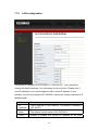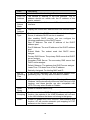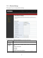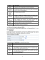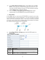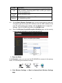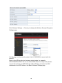
1
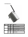
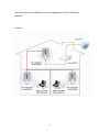
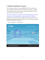
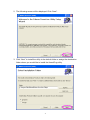
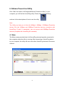
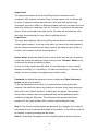
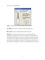
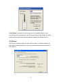
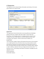
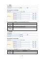
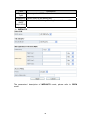
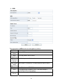
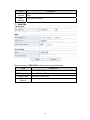
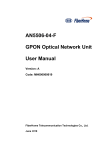
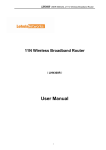
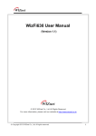
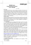
Copyright© by Edimax Technology Co, LTD. all rights reserved. No part of this publication may be reproduced, transmitted, transcribed, stored in a retrieval system, or translated into any language or computer language, in any form or by any means, electronic, mechanical, magnetic, optical, chemical, manual or otherwise, without the prior written permission of this company This company makes no representations or warranties, either expressed or implied, with respect to the contents hereof and specifically disclaims any warranties, merchantability or fitness for any particular purpose. Any software described in this manual is sold or licensed "as is". Should the programs prove defective following their purchase, the buyer (and not this company, its distributor, or its dealer) assumes the entire cost of all necessary servicing, repair, and any incidental or consequential damages resulting from any defect in the software. Further, this company reserves the right to revise this publication and to make changes from time to time in the contents hereof without obligation to notify any person of such revision or changes. The product you have purchased and the setup screen may appear slightly different from those shown in this QIG. For more detailed information about this product, please refer to the User Manual on the CD-ROM. The software and specifications are subject to change without notice. Please visit our web site www.edimax.com for the update. All rights reserved including all brand and product names mentioned in this manual are trademarks and/or registered trademarks of their respective holders. Notice according to GNU/GPL-Version 2 This product includes software that is subject to the GNU/GPL-Version 2. You find the text of the license on the product cd/dvd. The program is free software and distributed without any warranty of the author. We offer, valid for at least three years, to give you, for a charge no more than the costs of physically performing source distribution, a complete machine-readable copy of the corresponding source code. Please contact Edimax at: Edimax Technology co., Ltd, NO. 3, Wu-Chuan 3rd RD Wu-Ku-Industrial Park, Taipei Hsien, Taiwan. R.O.C., TEL : +886-2-77396888, FAX : +886-2-77396887, [email protected] 1. Product Introduction Thank you for purchasing and using Edimax HP-2002APn 200Mbps PowerLine Ethernet Adapter with wireless Access Point. This device allows you to use your home or office’s existing electrical wiring to create a network for multiple computers to share files or connecting DVR, X-Box or Set-top Box device to join the network. Using the existing AC outlet, you can obtain greater flexibility in arrangement of a new network with your existing wired or wireless network. No extra cost is needed. This product complies with the HomePlug AV mode and IEEE802.11b/g (compatible with 1T1R 802.11n) wireless standards which providing up to 200Mbps / 150Mbps data transfer rate. This product enables you to create a network easily and cost-effectively, it is a good choice for you to create a new network or rearrangement of the existing network. Note : 14Mbps and 85Mbps Powerline devices (complies with HomePlug 1.0 and 1.1 standards ) can not connect with 200Mbps Powerline devices (complies with HomePlug AV standard). 1 2. Product Package This package contains the following components: One HP-2002APn PowerLine 200Mbps Ethernet Adapter One RJ-45 Cable (100cm) One Quick Installation Guide One CD-ROM (Including all the software utilities, drivers, Multi-languages Quick Installation Guide and User’s Manual) If any item is missing or damaged, please contact your local resellers for service. Note:CD-ROM with the management Utility could help you to manager all of the HomePlug devices in the LAN. The Utility is not necessary when you use the internet via HP-2002APn. 2 3. LED Definitions LED Indicator Color Status Description PWR Red On Power is on. Green On The device runs normally. - Off Power is off or the device is down. Green On Radio switch is turned on. Green Blink Data is being transmitted. - Off Radio switch is shut off. Green On Connection succeeds Protected Setup. Green Blink Negotiation is in progress under Wi-Fi Protected Setup. WLAN WPS 3 under Wi-Fi PLC LAN Off Green On/Blink Orange On/Blink Red On/Blink Wi-Fi Protected Setup is disabled. When PLC rate﹥100Mbps, see note 1 When PLC rate in 80-100Mbps, see note 1 Green On Connection succeeds. Green Blink Data is being transmitted. - Off No LAN connection. When PLC rate﹤100Mbps, see note 1 Note: The PLC LED indicator turns “ON” when powerline link is detected. If the device is serving as a STATION, the LED indicator will blink to indicate transmit or receive powerline activity. If the device is serving as a CCO, the LED indicator will light steadily ON, even in the presence of powerline activity 4. Hardware Installation Procedure 1. Unpack the package and verify that all the items listed in the previous section are provided. 2. Connect the HomePlug product to the device which you want to add to a powerline network through the Ethernet cable. 3. Plug the HomePlug product to the power outlet. 4. This device with the HomePlug will join in the powerline network automatically. 5. Buttons : Reset: The Reset button can restore the factory defaults. Group: The button is used to synchronous the private network name. WPS: This button is used for enabling WPS PBC mode. If WPS is enabled, press this button, and then the extender starts to accept the negotiation of PBC mode Note: Do not press the Reset button unless you want to clear the current settings. The Reset button is in a small circular hole on the rear panel. If you want to restore the default settings, please press the Reset button gently for 3 seconds with a fine needle inserted into the hole and then release the button. The system reboots and returns to the factory defaults. 4 The following is the architecture of various applications of the HomePlug products. Picture 1 : 5 5. Software Installation Procedure The Configuration Utility for Windows 98SE/Me/2000/XP/Vista enables the users to identify HomePlug devices within the powerline network, measures data rate performance, ensures privacy and performs diagnostics by setting user defined secure powerline networks. The Utility could help you to manager all of the HomePlug devices in the LAN. The Utility is not necessary when you use the internet via HP-2002APn. Please follow the procedures below to install the utility. Please note that the following procedures are running in Windows XP, for other Windows operating systems, the procedures are similar. 1. Click “ Setup Utility “ to install Utility . 6 2. The following screen will be displayed. Click “Next”. 3. Click “Next” to install the utility in the default folder or assign the destination folder where you would like to install the HomePlug utility. 7 4. Click “Finish” to complete the installation. 8 6. Edimax PowerLine Utility Click “Start” and select “All Programs\Edimax PowerLine Utility” in your computer, you will find the HomePlug utility. Please refer to the following sections for the descriptions of how to use the utility. Note : The Utility can help you to find all (14Mbps / 85Mbps / 200Mbps) Powerline devies. But the 14Mbps and 85Mbps Powerline devices (complies with HomePlug 1.0 and 1.1 standards ) can not connect with 200Mbps Powerline devices (complies with HomePlug AV standard). 6.1 Main The Main screen provides lists of all HomePlug devices logically connected to the computer when the utility is running. After connecting a HomePlug device to your computer, the utility will auto scan other HomePlug devices in the same network. 9 Upper Panel The upper panel shows all local HomePlug devices connected to the computer’s NIC (Network Interface Card). In most cases, only one device will be seen. In situations where there are more than one local device being connected, such as a USB or an Ethernet adapter, the user can select the local device by clicking on it and then click the “Connect” to connect to the selected device. Once connected to the local device, the utility will automatically scan the power line periodically for any other HomePlug devices. Lower Panel The lower panel displays all the HomePlug remote devices, discovered on the current logical network. In the top of the table, you can see the total number of remote devices connected on the same network, the Network type (Public or Private) of the network and the scanning status. Device Name: shows the default device name, which may be user re-defined. A user can change the name by either clicking on the “Rename” button or by clicking on the name and editing in-place. An icon is usually shown with the name. A color distinction in icons is made between HomePlug 1.0, HomePlug 1.0 Turbo and HomePlug 1.1 devices. By default, the icon is always accompanied by a device name. Password: by default the password column is blank and ‘Enter Password’ button can be used to enter it. To set the Password of the device (it is required when creating a private network), first select the device by clicking on its name in the lower panel and then click on the “Enter Password”. A dialog box will appear. The selected device name is shown above the password field and the password can be verified by hitting the OK button. The Password field accepts the Device password in any case formats, with or without dashed between them. Note 1: The device must be present on the power line (plugged in) in order for the password to be confirmed and added to the network. If the device could not be located, a warning message will be shown. Note 2: Please find the password of the HomePlug device in the rear panel. 10 The “DAK” code is the password. Quality: the status of the connection quality will be shown here. Rate (Mbps): show the current data rate of the HomePlug device. MAC Address: the device’s MAC address will be shown here. Add Button: it is used to add a remote device to the existing network by entering the device password of the device. A dialog box will appear as below. The dialog box allows the user to enter both a device name and the password. A confirmation box will appear if the password was entered correctly and if the device was found in the powerline network. If a device was not found, the user will be notified and suggestions to resolve common problems will be presented. 11 Scan Button: the button is used to perform an immediate search of the HomePlug devices connected to the Powerline network. By default, the utility automatically scans every few seconds and updates the display screen. 6.2 Privacy The Privacy screen provides the user with an option to maintain security for their logical network and also to select the devices that has to be included in the network. 12 Private Network Name: All HomePlug devices are shipped using a default logical network (network name), which is normally “HomePlug”. If you wan to set a privacy network, change the network name. Use Default (Public Network): The user can always reset to the HomePlug network (Public) by entering “HomePlug” as the network name or by clicking on the “Use Default (Public Network)”. Set Local Device Only: The button can be used to change the private network name to all of the local devices. If a new network name is entered, all the devices seen on the top panel of Main screen prior to this will be no longer present in the new network. You have to set the new network name to all local devices. Set All Devices: The button is used to set the new network name (network password) to all HomePlug devices whose password has been entered for the same logical network. A dialog window will appear to report the success of this operation. For devices whose password is not entered, this operation will fail and will report a failure message. 13 6.3 Diagnostics The Diagnostics screen shows System information and a history of all remote devices seen over a period of time. Upper Panel The Upper panel shows technical data concerning software and hardware present on the host computer which were used to communicate over HomePlug on the Powerline network. It includes powerline network name, computer user name, MAC Address of all NICs (Network interface card) connected to the computer, versions of all drivers and utilities, etc. Lower Panel The Lower panel contains a history of all remote devices seen on the computer over a certain period of time. All devices that were on the powerline network are listed here along with a few other parameters. Devices that are active on the current logical network will show a transfer rate in the Rate column; devices on other networks, or devices that may no longer exist are shown with a “?” in the Rate column. The following remote device information is available from the diagnostics screen: Device Alias Name Device MAC Address 14 Device Password Device Last known rate Device Last Known Network name HomePlug chipset manufacturer name Date device last seen on the network MAC Firmware Version. (Turbo Only) The diagnostics information displayed may be saved to a text file for later use, or can be printed for reference for a technical support call. Devices, which are not part of the network anymore, can be deleted using the delete button. A dialog window pops up with a confirmation message if we try to delete a device whose password has been entered. 6.4 About The About screen shows the software version information. You can select “AutoScan” to turn on or off the auto-scan function. 15 7. Wireless Access Point Configuration 7.1 IP Setting You can configure the HP-2002APn wireless setting by running the Setup Wizard in the CD-ROM provided in the package. The wizard provides quick setup for the SSID, wireless security of WPA-PSK and changing password of HP-2002APn. When you start the Setup Wizard, you will get the following Welcome screen. Please choose the language to start with and follow the easy steps in the Wizard. No instruction for the Setup Wizard is given here. If you lost the CD-ROM or you prefer the traditional web setup, please follow the procedures in this Manual to configure the HP-2002APn The default IP address of HP-2002APn is ‘192.168.2.8’.Before you start the Wizard or start to login HP-2002APn, you should make sure your computer’s IP address is in the same segment (192.168.2.XXX where XXX=10~253 ) of HP-2002APn . 1. Click ‘Start’ button (it should be located at lower-left corner of your computer), then click control panel. Double-click Network and Internet Connections icon, click Network Connections, then double-click Local Area Connection, Local Area Connection Status window will appear as follows. 16 2. Select ‘Use the following IP address ’ and you can assign “192.168.2.XXX” (where XXX=10~253), then click ‘OK’. Note : If your original setting of computer is “Obtain an IP address automatically “ & “Obtain DNS server address automatically“ , you should reset to original settings when you finish the following HP-2002APn configuration. 17 7.2 Wireless configuration via EZmax CD Wizard After you finish IP address configuration of computer, you can start the Setup of EZmax Wizard, and you will get the following Welcome screen. Please choose the language to start with and follow the easy steps in the Wizard. No instruction for the Setup Wizard is given here. If you lost the CD-ROM or you prefer the traditional web setup, please follow the procedures in this Manual to configure the HP-2002APn Note : If your original setting of computer is “Obtain an IP address automatically “ & “Obtain DNS server address automatically“ , you should reset to original settings when you finish the following HP-2002APn configuration. 18 7.3 Wireless configuration via Web Setup If you prefer the traditional web setup, please follow the procedures in this Manual to configure the HP-2002APn. The default IP address of HP-2002APn is “ 192.168.2.8 “ . Please input ‘admin’ in ‘User name’ field, and ‘1234’ in ‘Password’ field, and click ‘OK’ button to enter web configuration interface. After login, the default page Status appears, and this page shows the status information, including firmware version, LAN interface, wireless channel and MAC address, and statistic information. 19 Device Info – This page shows you “Firmware Version / MAC address / IP address and Wireless information” LAN For you to setup HP-2002APn’s IP address, enable/disable DHCP, IGMP and IP address pool. Wireless You can setup SSID, wireless security and ACL here. Management For you to upgrade HP-2002APn’s firmware, save current settings, reboot, reset to default settings and change password. 20 7.3.1 LAN configuration The default IP address of HP-2002APn is “192.168.2.8”, if you would like change the default settings. You can assign a new one here. Please note if new IP address is not in same segment with current IP address of your desktop, you will not configure HP-2002APn unless you change computer’s IP address again. Field Description IP Address The IP address of LAN interface. The default IP address is 192.168.2.8. Subnet Mask The subnet mask of the IP address of the LAN interface. The default subnet mask is 255.255.255.0. LAN 2 Enable or disable the second IP address of the LAN 21 Field Description interface. The default setting is Disable. LAN 2 IP Address The second IP address of the LAN interface. This IP address should not collide with the IP address of the interior network. LAN 2 Subnet Mask The subnet mask of the second IP address of the LAN interface. MAC Address Display the current MAC address that LAN interface uses. DHCP Type Enable or disable DHCP service. The default setting is Server, it indicates DHCP service is enabled. After enabling DHCP service, you can configure the following parameters of the DHCP server: Start IP Address: The start IP address of the DHCP address pool. End IP Address: The end IP address of the DHCP address pool. Subnet Mask: The subnet mask that DHCP server assigns. Primary DNS Server: The primary DNS server that DHCP server assigns. Secondary DNS Server: The secondary DNS server that DHCP server assigns. Default Gateway: The gateway that DHCP server assigns. Lease Time: The lease time of the IP address. Statically Assigned: For binding MAC and IP. 802.1d Spanning Tree It can provide redundant link and prevent network from generating loop. You may select Enable or Disable. LLTD After enabling LLTD (Link Layer Topology Discovery), Windows Vista automatically discovers other devices’s link topology, and these devices are also compatible with LLTD. You may select Enable or Disable. IGMP Proxy Enable or disable IGMP Proxy. IGMP Snooping Enable or disable IGMP Snooping. After enabling this function, the packets of the IGMP broadcast will not sent to the LAN interface that does not belong to that group. UPNP Enable or disable the UPnP function. After enabling this function, AP will provide automatic port-mapping for P2P software on the interior network. 22 7.3.1 Wireless Settings This page is for you to setup wireless settings. The parameters of Wireless Network are described as follows: Field Description Radio On/Off Enable or disable wireless LAN interface. Network Mode You may select a proper network mode in the drop down list. 11b/g mixed mode 11b only 11g only 11b/g/n mixed mode (default) Network The maximum character number for SSID is 32 23 Field Name (SSID) Description characters. The legal characters include letter, number underline or the combination of these characters. Multiple SSID1~7 Accessional network SSID. Each SSID can use wireless security setting independently. Broadcast Network Name (SSID) Whether to broadcast SSID. After enabling this function, AP will broadcast its SSID. AP Isolation Enable or disable the isolation among AP clients. After enabling this function, the client terminals that connect to the same AP can not communicate each other. MBSSID AP Isolation Enable or disable the isolation among different SSIDs. After enabling this function, the client terminals with different SSIDs can not communicate each other. BSSID The MAC address of the wireless interface. Frequency (Channel) You may select a proper channel in the drop down list. The default channel is Channel 6. Wireless Distribution System (WDS) WDS modes include Lazy Mode, Bridge Mode, and Repeater Mode. You can also enable WDS. 1) Lazy Mode In the lazy mode, AP automatically connects to the WDS devices that use the same SSID, channel, encryption mode, and the physical mode. You do not need to manually enter other MAC addresses of peer APs. The parameters of Lazy Mode are described as follows: Field Description WDS Mode Select the Lazy Mode in the drop down list. Phy Mode The physical modes in the drop down list include CCK, OFDM, HTMIX, and GREENFIELD. Encryp Type The encryption types you can select include NONE, WEP, TKIP, and AES. If selecting WEP, TKIP, or AES, you need to set the encryption key. Encryp Key Set the encryption key. 24 Step 1 Step 2 On the Basic Wireless Settings page, set the WDS mode to be Lazy Mode, set the same phy mode and encryp type with the peer AP, and then enter the MAC address of the peer AP. After finishing the settings, click the Apply button to apply the settings. Enter the Wireless Security/Encryption Settings page, set the security mode of the HP-2002APN to accord with the peer AP. 2) Bridge Mode In the bridge mode, you can use the HP-2002APN to connect to your router, for extending wireless coverage. Meanwhile, it can also decrease the working load of the AP that accesses the Internet. In that case, the wireless card does not directly communicate with the wireless device that accesses the Internet, but it directly communicates with the HP-2002APN. Step 1 On the Basic Wireless Settings page, select the WDS mode to be Bridge Mode. Field Description WDS Mode Select the Bridge Mode. Phy Mode The physical modes in the drop down list include CCK, OFDM, HTMIX, and GREENFIELD. 25 Field Encryp Type The encryption types you can select include NONE, WEP, TKIP, and AES. If selecting WEP, TKIP, or AES, you need to set the encryption key. Encryp Key Set the encryption key. AP MAC Address Step 2 Step 3 Description The MAC address of another AP that connects to the HP-2002APN by WDS. On the Basic Wireless Settings page, set the same physical mode and encryption type with the peer AP, and then enter the MAC address of the peer AP. After finishing the settings, click the Apply button to apply the settings. The HP-2002APN will work in the Bridge mode. Enter the Wireless Security/Encryption Settings page, set the security mode of the HP-2002APn to accord with the peer AP. 3) Repeater Mode In the Repeater mode, you can use the HP-2002APN to connect to the primary router, for extending the wireless coverage. 4) Click Wireless Settings --> Basic to display Basic Wireless Settings page. 26 Set the Frequency(channel) according with the peer AP (An AP that wants to connect to the HP-2002APN by WDS). On the Basic Wireless Settings page, set the WDS mode to be Repeater Mode, set the same physical mode and encryption type with the peer AP, and then enter the MAC address of the peer AP. After finishing the settings, click the Apply button to apply the settings. The HP-2002APN will work in the Repeater Mode. 27 Click Wireless Settings --> Security to display the Wireless Security/Encryption Settings page. On this page, set the security mode of the HP-2002APN to accord with the peer AP. Note: In the WDS mode, don’t set any mixed modes, for example, WPA-PSK/WPA2-PSK. Do not set all the WDS APs to be Lazy mode, please ensure that at least one WDS AP acts as Root Bridge, and enter the MAC addresses in the WDS table on the Basic Wireless Settings page 28 HT Physical Mode The parameters of HT Physical Mode are described as follows: Field Description Operation Mode You may select Mixed Mode or Green Field. The default operation mode is Mixed Mode. Channel BandWidth You may select 20 or 20/40. The default channel bandwidth is 20/40. Guard Interval You may select Long or Auto. The default guard interval is Auto. MCS You may select the MCS value from 0 to 32. The default MCS is Auto. Reverse Direction Grant (RDG) You may select Disable or Enable. The default RDG setting is Enable. Extension Channel When the channel bandwidth is set to be 20/40 MHz, the extension channel will provide a channel that is adjacent to the primary channel but not overlaps. The wireless network will acquire diploid bandwidth by this extension channel, that is, 20MHz bandwidth. Note: IEEE 802.11n can bind two adjacent 20 MHz bandwidths together to form a 40MHz bandwidth. Actually, the 40MHz bandwidth can act as two 20 MHz bandwidths. One is primary bandwidth, the other is 29 Field Description secondary bandwidth. When data is being transmitted, it can act as 40MHz bandwidth, and it can also acts as 20 MHz bandwidth independently. In this way, the data rate is doubled. Aggregation Enable or disable A-MSDU. MSDU MSDU is the aggregation of multiple MSDUs by using (A-MSDU) certain method and the multiple MSDUs forms a greater load. MSDU can be considered as Ethernet message. Usually, when AP or wireless client receives MSDUs from protocol stack, the MSDUs will be marked with the Ethernet message header (also called A-MSDU Subframes). Before sending them out, the A-MSDU Subframes need to be transformed into the message format of 802.11 one by one. A-MSDU aggregates multiple A-MSDU Subframes and encapsulates them to be an 802.11 message. In this way, PLCP Preamble, PLCP Header, and 802.11 MAC overhead that are needed to send an 802.11 message decrease. At the same time, the acknowledge frames also decrease, and the efficiency for sending message is improved. Auto Block ACK Enable or disable Auto Block ACK. In order to insure the security of the data transmission, 802.11n protocol requires that if client receives a uincast frame, it should immediately send back an ACK frame. After the receiver of A-MPDU receives A-MPDU, it needs to process every MPDU. In that case, it sends out ACK frames to every MPDU. Block Acknowledgement is used to reduce the number of the ACK frames by using an ACK frame. Decline BA Request Enable or disable Decline BA Request. 30 7.3.1 Advanced Wireless Settings On this page, you may configure advanced wireless parameters, such as beacon interval, data beacon rate, and Tx power. Note: The advanced wireless setting is only for advanced user. For the common user, do not change any setting on this page. Advanced Wireless The parameters of Advanced Wireless are described as follows: 31 Field Description BG Protection Mode You may select On, Off, or Auto. The default BG protection mode is Auto. Beacon Interval By default, wireless beacon signal sends data to station every other 100 ms. The range is 20~999. Data Beacon Rate (DTIM) The default DTIM is 1ms. The range is 1~255. Fragment Threshold The default fragment threshold is 2346. The range is 256~2346. RTS Threshold The default RTS threshold is 2347.The range is 1~2347. TX Power Set the Tx power. 100% indicates full power. Short Preamble Enable or disable short preamble. The default setting is Disable. Preamble defines the length of CRC correction block for wireless devices. Short preamble adopts 56-bit synchronization field. The network whose network stream is dense should use shorter preambles. Short Preamble is mainly applied to improvement the efficiency of real- time applications, such as streaming video, and Voice-Over-IP telephony. Short Slot Enable or disable short slot. Tx Burst Tx Burst can be used to improve the efficiency of data transmission. It can make system transmit more data during a period of time. Pkt_Aggregate Pkt_Aggregate can aggregate multiple data packets together for improving the transmission efficiency Country Code Select a proper country code in the drop down list. Wi-Fi Multimedia The parameters of WMM are described as follows: Field Description WMM Capable Enable or disable WMM. After enabling WMM, AP can process different types of wireless data according to their priority levels. APSD Capable Enable or disable APSD. After enabling APSD, it can decrease the consumption of the power supply device. DLS Capable Enable or disable DLS WMM Parameters Click the WMM Configuration button to display WMM parameters configuration page. 32 1) WMM Access Categories At present, WMM defines traffic into 4 access categories. AC_VO: Voice (highest priority) AC_VI: Video (high priority) AC_BE: Best effort (medium priority) AC_BK: Background (low priority) 802.11 uses DCF (Distributed Coordination Function) scheme of the CSMA/CA (Carrier Sense Multiple Access / Collision Avoidance) protocol to reduce the chances of packets collision while one more devices access the wireless media at the same time. A client wishing to transmit has to first listen to the channel for a predetermined amount of time so as to check for any activity on the channel. If the channel is sensed "idle" then the client is permitted to transmit. If the channel is sensed as "busy" the station has to defer its transmission. The random interval provides a fair transmission chance for all the devices. When each priority queue waits for sending packets, it has to wait a fixed time AIFSN and a random time CW. They define time values by multiple time slots. For 802.11b, its time slot is 20ms. The time slot of 802.11a and 802.11g is 9 ms. CW insures the random delay time of DCF, so that the packets collision among the devices with the same access category can be avoided. If collision occurs, CW is doubled until exceeds its maximum value. After every successful transmission, CW returns to the minimum value. The priority queue that succeeds in the competition of sending packets, it will acquire Txop time to send packets. If the txop value is 0, it is limited to be a MSDC (MAC Service Data Unit). 33 2) Set WMM Parameters Click the WMM Configuration button, the following page appears. On this page, you can configure WMM parameters of access point and station.The parameters are described as follows: Field Description Aifsn Aifsn (Arbitrary Inter-Frame Space Number). This parameter influences the delay time of WMM access category. If you use voice or video service, you’d better set this parameter to be smaller in the fields of AC_VI and AC_VO. If it is E-mail or Web service, you should set a bigger value in the fields of AC_BE and AC_BK. Cwmin Cwmin (Mini. Contention Window) also influences the delay time of WMM access category. The difference between AC_VI and AC_VO should be smaller, but the difference between AC_BE and AC_BK should be bigger. Cwmax Cwmax (Max.Contention Window) Txop Txop (Opportunity to Transmit) may optimize the WMM access. Compared to the WMM access that needs a higher priority, such as AC_VI and AC_VO, this value should be bigger. ACM ACM (Admission Control Mandatory) parameter only reacts on AC_VI and AC_VO. If you set this value to be 0, it indicates that AP is in the charge of the access commands. 34 Field Description If this value is 1, it means the client is in the charge of the access commands. Ackpolicy When WMM packets are transmitting, AP will receive an echo request. If you set this value is 0, it means AP does not send back an echo request, which will brings positive effect for WMM. If this value is 1, AP generates the response to the request. Note: HP-2002APN provides standard WMM settings. If you want to modify the parameters above, please refer to the WMM settings of your WMM products. 3) DLS (Direct Link Setup) HP-2002APN provides DLS function. Suppose that there are two WMM devices. Enter the MAC address of a WMM device in the DLS setting of the other device, and then connect the two WMM devices to the HP-2002APN. In this way, the two WMM devices can transmit message directly. If you want to configure WMM DLS, do as follows: Step 1 Prepare two wireless network cards (A and B) and one HP-2002APN. Step 2 Enable the DLS function on the Advanced Wireless Settings page. Step 3 Enable the DLS function of wireless network cards. Enter the MAC address of wireless card A on the WMM page of the wireless network card B, and then click the Apply button. 35 Step 4 If DLS succeeds, you can view the MAC address of wireless card A on the WMM page of wireless card B, and vice versa. Multicast-to-Unicast Converter Enable or disable Multicast-to-Unicast. After enabling this function, the transmission quality of wireless multicast stream can be improved. 7.3.2 Security Click Wireless Settings --> Security Security/Encryption Settings page. 36 to display the Wireless This page allows you to configure wireless security modes and set the encryption keys, to prevent unauthorized access and monitoring. Select SSID SSID choice: select SSID that you want to configure. Security Mode This page provides 10 types of security modes, including OPEN, SHARED, WEPAUTO, WPA, WPA-PSK, WPA2, WPA2-PSK, WPAPSKWPA2PSK, WPA1WPA2, and 8021.X. 37 1) OPEN The parameters of OPEN mode are described as follows: Field Security Mode Description Select OPEN. Default Key Select a key as the default key. WEP Keys Set 64-bit or 128-bit key. The key format is Hex or ASCII. (WEP Key1/2/3/4) 2) SHARED The parameters of SHARED mode are described as follows: Field Description Security Mode Select SHARED. 38 Field Encrypt Type Description You may select WEP or None. Default Key Select a key as the default key. WEP Keys Set 64-bit or 128-bit key. The key format is Hex or ASCII. (WEP Key1/2/3/4) 3) WEPAUTO The parameters’ description of WEPAUTO mode, please refer to OPEN mode. 39 4) WPA The parameters of WPA mode are described as follows: Field Security Mode Description Select WPA. WPA Algorithms You may select TKIP or AES. Key Renewal Interval Set the key renewal interval. WEP Keys Set 64-bit or 128-bit key. The key format is Hex or ASCII. (WEP Key1/2/3/4) IP Address Port Shared Secret The IP address of RADIUS server. The default port number is 1812. You may change it according to the server setting. The shared key that RADIUS server needs to authenticate. 40 Field Description Session Timeout If this value is 0, it indicates that there is no session time limit. Idle Timeout Set the idle timeout. 5) WPA-PSK The parameters of WPA-PSK mode are described as follows: Field Security Mode WPA Algorithms Description Select WPA-PSK. Select TKIP or AES. Pass Phrase Set 8-bit to 64-bit key. Key Renewal Interval Set the key renewal interval. 41 6) WPA2 The parameters of WPA2 are described as follows: Field Security Mode WPA Algorithms Description Select WPA2. You may select TKIP, AES, or TKIPAES Key Renewal Interval Set the key renewal interval. PMK Cache Period Set the PMK (Pairwise Master Key) cache period. PMK scheme allows the roaming users that pass through the 802.11X/EAP handshake protocol roam to the previous AP again. PMK can decrease the roaming delay and improve the roaming speed. Pre-Authentication Enable or disable pre-authentication. WEP Keys (WEP Key1/2/3/4) Set 64-bit or 128-bit key. The key format is Hex or ASCII. 42 Field IP Address Port Shared Secret Session Timeout Idle Timeout Description The IP address of RADIUS server. The default port number is 1812. You may change it according to the server setting. The shared key that RADIUS server needs to authenticate. If this value is 0, it indicates that there is no session time limit. Set the idle timeout. 7) WPA2-PSK The parameters of WPA2-PSK mode are described as follows: Field Security Mode WPA Algorithms Description Select WPA2-PSK. You may select TKIP, AES, or TKIPAES. Pass Phrase Set 8-bit to 64-bit key. Key Renewal Interval Set the key renewal interval. 43 8) WPAPSKWPA2PSK The parameters’ description of WPAPSKWPA2PSK mode, please refer to WPA2-PSK. 44 9) WPA1WPA2 The parameters of WPA1WPA2 are described as follows: Field Security Mode WPA Algorithms Key Renewal Interval IP Address Description Select WPA1WPA2. You may select TKIP, AES, or TKIPAES. Set the key renewal interval. The IP address of RADIUS server. Port The default port number is 1812. You may change it according to the server setting. Shared Secret The shared key that RADIUS server needs to authenticate. Session Timeout If this value is 0, it indicates that there is no session time limit. Idle Timeout Set the idle timeout. 45 10) 802.1X The parameters of 802.1X mode are described as follows: Field Description Security Mode Select 802.1X. IP Address The IP address of RADIUS server. Port The default port number is 1812. You may change it according to the server setting. Shared Secret The shared authenticate. Session Timeout If this value is 0, it indicates that there is no session time limit. Idle Timeout Set the idle timeout. key that 46 RADIUS server needs to Access Policy The parameters of Access Policy are described as follows: Field Description Policy Disable: Stop the access control to the wireless devices in the MAC list. Allow: Allow the access control to the wireless devices in the MAC list. Reject: Reject the access control to the wireless devices in the MAC list. Add a Enter the MAC address of wireless device that you want to station allow or reject. Mac After finishing the settings, click the Apply button to apply the settings. 7.3.2.1 WPS Click Wireless Settings --> WPS to display the Wi-Fi Protected Setup page. 47 On this page, you can modify the WPS settings. WPS can make your client automatically synchronize with the AP setting, and establish connection. WPS Config 48 WPS: enable or disable WPS. After enabling WPS, you can configure the parameters related to WPS. WPS summary displays the preset WPS information, such as WPS current status, WPS authentication mode, and WPS encryption type. Click the Reset OOB button to display the WPS default settings. WPS Progress WPS modes include PIN and PBC modes, At present, WPS supports three operation modes, including Enrollee mode, Registrar mode, and PBC mode. Enrollee and Registrar modes need to apply PIN code negotiation. 1) Enrollee Mode Step 1 Select Enrollee mode on the wireless client, the software of wireless client will generate a random PIN code, for example, 12345678. Step 2 Step 3 On the Wi-Fi Protected Setup page, enter the PIN code of wireless client, for example, 12345678. Click the Apply button on the Wi-Fi Protected Setup page to submit setting. 2) Registrar Mode Step 1 View the AP PIN on the Wi-Fi Protected Setup page, for example, 31668729. 49 Step 2 Select Registrar mode on the wireless client and enter the PIN code of the HP-2002APN. See the following figure: 3) PBC Mode Step 1 On the Wi-Fi Protected Setup page, select the PBC mode, and then click the Apply button. You may also press the WPS button on the rear panel. Step 2 Enable the PBC function on the wireless client. In that case, HP-2002APN and wireless client will automatically establish connection. WPS Status 50 The figure above displays WPS current status. 7.3.2.2 Station List Click Wireless Settings --> Station List to display the Station List page. On this page, you can view the wireless networks that connect to the HP-2002APN. If there is any wireless network connects to HP-2002APN, refresh this page and the connection information of the wireless network is displayed. 51 7.3.2.3 Administration Click Administration --> Management to display the System Management page. This page provides administration settings, NTP settings, and DDNS settings. Administrator Settings The parameters of Administrator Settings are described as follows: Field Description Account Enter the account that you want to change. Password Enter the password for the new username. Note: If you forget the account and the password, please press the Reset button. The system will return to the factory default settings. The default account and the password are Admin. 52 7.3.2.4 Upload Firmware Click Administration --> Upload Firmware to display the Upload Firmware page. If you want to upload the firmware of the HP-2002APN, click the Browse… button to choose the correct new firmware, and then click the Apply button. System begins to upgrade firmware. After upgrading, system reboots and automatically enters the Web page. The procedure for upgrading Bootloader is similar to that of the firmware upgrade. Note: Upgrading firmware will make the AP return to the factory defaults. In order to avoid the settings loss, please save the settings before upgrading firmware. During upgrading, do not cut off the power or press the Reset button. 53 7.3.2.5 Setting Management Click Administration --> Settings Management to display the Settings Management page. The parameters on this page are described as follows: Field Export Settings Import Settings Description Click the Export button to save the settings on your local PC. Click the Browse… button to choose the settings on your PC, and then click the Import button to import the settings to AP. Load Factory Click the Load Default button, the system returns to the Defaults factory default settings. 54 Warning (1) Simply plug into a power outlet and do not use a power strip or UPS with the wall mount device (2)This is a class A product. In a domestic environment this product may cause radio interference in which case the user may be required to take adequate measures. (3) It is important to use the PLC product complying with the following "correct rules", because it can significantly improve the transmission capacity of the network. For the PLC device no female socket, it is recommended to plug the device directly into a wall socket, not to power stripe. Important Safety Instructions This product is intended for connection to the AC power line. The following pre-cautions should be taken when using this product: ‧Please read all instructions before installing and operating this product. ‧Please follow all warnings and instructions marked on the product. ‧Do not operate this product near water. ‧ This product should never be place near or over radiator, or heat register. ‧ This product relies on a building's electrical installation for short-circuit (over current) protection. ‧Unplug the device from the wall outlet before cleaning. Use a damp cloth for cleaning. Do not use liquid cleaners or aerosol cleaners. ‧Unplug the device from the wall outlet and refer the product to qualified 55 service personnel for the following conditions : # If liquid has been spilled into the product # If the product has been exposed to rain or water # If the product does not operate normally when the operating instructions are followed # If the product exhibits a distinct change in performance. 56 57