1
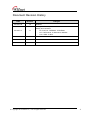
WizFi630 User Manual (Version 1.1) © 2012 WIZnet Co., Ltd. All Rights Reserved. For more information, please visit our website at http://www.wiznet.co.kr © Copyright 2012 WIZnet Co., Ltd. All rights reserved. 1 Certification Information CE for Class B ITE INFORMATION TO THE USER Hereby, WIZnet. Declares that this WizFi630 is in compliance with the essential requirements and other relevant provisions of directive 1999/5/EC and other relevant provisions of directive 1999/5/EC. WARNING: This is a class B product. In a domestic environment this product may cause radio interference in which case the user may be required to take adequate measures FCC for Class B ITE INFORMATION TO THE USER This equipment has been tested and found to comply with the limits for a Class B digital device, pursuant to part 15 of the FCC Rules. These limits are designed to provide reasonable protection against harmful interference in a residential installation. This equipment generates, uses and can radiate radio frequency energy and, if not installed and used in accordance with the instructions, may cause harmful interference to radio communications. However, there is no Guarantee that interference will not occur in a particular installation. If this equipment does cause harmful interference to radio or television reception, which can be determined by turning the equipment off and on, the user is encouraged to try to correct the interference by one more of the following measures: - Reorient or relocate the receiving antenna. Increase the separation between the equipment and receiver. Connect the equipment into an outlet on a circuit different from that to which the receiver is connected. - Consult the dealer or an experienced radio/TV technician for help. WARNING: This equipment may generate or use radio frequency energy. Changes or modifications to this equipment may cause harmful interference unless the modifications are expressly approved in the instruction manual. The user could lose the authority to operate this equipment if an unauthorized change or modification is made © Copyright 2012 WIZnet Co., Ltd. All rights reserved. 2 Document Revision History Date Revision 2012-07-02 1.0 Release 1.1 Change WizFi630’s picture at P10 Modify error sentence - P6, P18,P19 : WIZ630wi Æ WizFi630 - P24 : DNS server Æ DNS server address - P38 : WDS Æ WPS 2012-07-17 Changes © Copyright 2012 WIZnet Co., Ltd. All rights reserved. 3 <Contents> 1. 2. Introduction .................................................................................. 6 1.1. 1.2. 1.3. 1.4. 1.5. 1.5.1. 1.6. Features .............................................................................................................................................. 7 Wireless Specifications ................................................................................................................. 8 Hardware Specifications............................................................................................................... 9 Software Specifications ............................................................................................................. 10 EVB Construction ......................................................................................................................... 10 Contents .......................................................................................................................................... 10 Block Diagram ............................................................................................................................... 12 Operation Mode and Description of Menu ......................... 13 2.1. Operation Mode .......................................................................................................................... 13 2.1.1. Access Point .................................................................................................................................. 13 2.1.2. Gateway........................................................................................................................................... 14 2.1.3. Client (Station) .............................................................................................................................. 14 2.1.4. AP-Client Mode ........................................................................................................................... 15 2.1.5. Ad-hoc Mode ............................................................................................................................... 15 2.2. Menu List by Operation Mode .............................................................................................. 16 2.2.1. Access Point (Bridge) Mode .................................................................................................. 16 2.2.2. Gateway (Router) Mode ........................................................................................................... 17 2.2.3. Client (Station) Mode ................................................................................................................ 18 2.2.4. AP-Client Mode ........................................................................................................................... 19 2.2.5. Ad-hoc Mode ............................................................................................................................... 21 2.3. Internet Setting............................................................................................................................. 23 2.3.1. Internet connection setting ................................................................................................... 23 2.3.2. Local network setting ............................................................................................................... 25 2.3.3. DHCP Client Information ......................................................................................................... 26 2.3.4. VPN setting.................................................................................................................................... 26 2.3.5. Static Routing Setting .............................................................................................................. 27 2.3.6. QoS(802.1p) Setting ................................................................................................................... 28 2.3.7. VLAN(802.1p) ................................................................................................................................ 29 2.4. Wireless setting ............................................................................................................................ 30 2.4.1. Basic settings ................................................................................................................................ 30 2.4.2. Advanced Wireless Settings .................................................................................................. 32 2.4.3. Wireless Security ......................................................................................................................... 35 2.4.4. WDS(Wireless Distribution System) Setting ..................................................................... 38 2.4.5. WPS Setting ................................................................................................................................... 39 2.4.6. Wireless network status............................................................................................................ 41 2.4.7. AP Wireless Statistics ................................................................................................................. 42 2.4.8. Station QoS/DLS(Direct Link Setup) Configurations ..................................................... 44 2.4.9. Profile ............................................................................................................................................... 45 2.4.10. Link Status ...................................................................................................................................... 46 2.4.11. Site Survey ..................................................................................................................................... 47 2.4.12. WI-FI Multi-Bridge settings..................................................................................................... 48 2.5. Serial to LAN(Wired and Wireless) ....................................................................................... 49 2.5.1. Main Connection settings ....................................................................................................... 50 © Copyright 2012 WIZnet Co., Ltd. All rights reserved. 4 3. 4. 2.5.2. 2.5.3. 2.5.4. 2.6. 2.6.1. 2.6.2. 2.6.3. 2.6.4. 2.6.5. 2.7. 2.7.1. 2.7.2. 2.7.3. 2.7.4. 2.7.5. 2.7.6. 2.7.7. Aux Connection Settings ......................................................................................................... 50 Packing Condition (Incoming serial data packing condition)................................... 51 Ethernet Data Tagging Option .............................................................................................. 51 Firewall settings ............................................................................................................................ 52 DMZ .................................................................................................................................................. 52 Port forwarding ............................................................................................................................ 53 Packet filtering .............................................................................................................................. 54 Contents filtering ........................................................................................................................ 55 System Security ............................................................................................................................ 56 Managements ............................................................................................................................... 57 System Management ................................................................................................................. 57 Firmware ......................................................................................................................................... 58 Config Settings ............................................................................................................................ 59 Port Setting.................................................................................................................................... 60 Packet Statistics ............................................................................................................................ 61 System Status ................................................................................................................................ 62 System Log .................................................................................................................................... 63 3.1. 3.2. WizFi630 Pin Map........................................................................................................................ 64 Dimensions ..................................................................................................................................... 66 Hardware Information ............................................................. 64 Important Notice ...................................................................... 67 © Copyright 2012 WIZnet Co., Ltd. All rights reserved. 5 1. Introduction WizFi630 is a gateway module that transforms the RS-232 protocol and TCP/IP protocol into IEEE802.11 b/g/n wireless LAN protocol. WizFi630 enables a device with RS-232 serial interface to connect to LAN or WLAN for remotely control, measuring, and administration. WizFi630 can also work as an IP router because of its internally embedded switch. WizFi630 uses interfaces like Serial(UART), LAN, Wi-Fi(WLAN) to perform functions such as Serial(UART)-To-Wi-Fi, Serial-To-Ethernet, Ethernet-To-Wi-Fi. Users can connect to WizFi630’s internal web server or use serial commands for simple Wi-Fi settings; not only serial devices but 8/16/32 bit micro controllers can also use UART for simple Wi-Fi settings. WizFi630 can significantly reduce the processes for wireless module design, testing, and certification. Therefore, WizFi630 can be the best solution for users who lack wireless network experience. WizFi630 follows the 802.11b/g/n standard and support up to 150Mbps speed in wireless interface. WizFi630 provides a test board, pc software, and documents so that anyone can develop a wireless solution. © Copyright 2012 WIZnet Co., Ltd. All rights reserved. 6 1.1. Features Complies with IEEE802.11b/g/n. Gateway/AP(Bridge)/AP-Client/Client(Station)/Ad-hoc Mode , WDS/Repeater supports 1T1R RF Interface Physical link rate up to 150Mpbs Built-in 3 Ethernet Ports 2 Serial Ports supports Working as Wi-Fi Router WEP 64/128bit, WPA/WPA2-PSK TKIP, AES 802.1x (Only in AP mode) 802.11e and WMM (Wi-Fi Multimedia) Router and Firewall function supports Figure 1. Example of WizFi630’s Application © Copyright 2012 WIZnet Co., Ltd. All rights reserved. 7 1.2. Wireless Specifications Type Wireless Standard Description IEEE802.11b/g/n USA: 2.400 ~ 2.483GHz Frequency Range Europe: 2.400 ~ 2.483GHz Japan: 2.400 ~ 2.497GHz China: 2.400 ~ 2.483GHz USA/Canada: 11(1 ~ 11) Major Europe Countries: 13(1 ~ 13) Operating Channels France: 4(10 ~ 13) Japan: 14 for 802.11b(1 ~ 14), 13 for 802.11g(1 ~ 13) Korea/China: 13(1 ~ 13) Output Power (Tolerance(+/-1dBm) 802.11b: 17dBm@11Mbps 802.11g: 14dBm@54Mbps 802.11n: 14dBm@150Mbps/72Mbps 802.11b: -89dBm@11Mbps Receive Sensitivity 802.11g: -74dBm@54Mbps 802.11n(40MHz): -66dBm@150Mbps 802.11n(20MHz): -70dBm@72Mbps 802.11b: 1,2,5.5,11Mbps Data Rates 802.11g: 6,9,12,18,24,36,48,54Mbps 802.11n(20MHz): 7,14.5,21.5,28.5,43.5,57.5,65,72Mbps 802.11n(40MHz): 29.5,86.5,115,130,144,150Mbps Modulation Type Antenna 11g: OFDM(64QAM, 16QAM, QPSK, BPSK) 11b: DSS(CCK, DQPSK, DBPSK) u.FL (EVB : 1T1R 2dBi) Table 1. Wi-Fi Specifications © Copyright 2012 WIZnet Co., Ltd. All rights reserved. 8 1.3. Hardware Specifications Type Description Serial port : 2 EA Interface LAN port : 3EA USB port : 1 USB Host Port ( Reserved ) U.FL(wireless) Temperature Humidity Operation: -10℃~70℃ Operation: 10% to 90%, Non-Condensing Storage: 5% to 90%, Non-Condensing Baud Rate : 1200 ~ 921,600bps Stop bits: 1, 2 Serial Parity: None, Odd, Even Flow Control: UART1: XON/XOFF(software), CTS/RTS(hardware), none UART2: XON/XOFF, none Input Power Power Consumption Dimension Weight DC 3.3V / 1A Max : 3.3V / 600mA 33mm X 43mm X 4.5mm 6g Table 2. WizFi630 Module Specifications © Copyright 2012 WIZnet Co., Ltd. All rights reserved. 9 1.4. Software Specifications Type Operation Mode Protocol Description Access Point(Bridge), Client(Station), Gateway, AP-Client, ad-hoc TCP, UDP, ARP, ICMP, DHCP, PPPoE, HTTP WEP 64/128bit Security WPA/WPA2-PSK AES/TKIP 802.1x ( Only in AP Mode ) Configuration Notification Serial To Wi-Fi Web Configuration, Serial Command, Configuration Tool Event Logging 2 Serial Port supports Table 3. SW Specifications 1.5. EVB Construction 1.5.1. Section Contents Qnt. Contents WizFi630 WizFi630 1ea WizFi630-EVB WizFi630EVB 1ea © Copyright 2012 WIZnet Co., Ltd. All rights reserved. 10 2dBi WI-FI Antenna (Model : W5I-B0-08) Antenna 1 ea Serial Cable Serial Cable 1 ea LAN Cable LAN Cable 1 ea DC 5V/2A Adapter Adapter 1ea Table 4. WizFi630-EVB Contents © Copyright 2012 WIZnet Co., Ltd. All rights reserved. 11 1.6. Block Diagram Figure 1. WizFi630 Block Diagram © Copyright 2012 WIZnet Co., Ltd. All rights reserved. 12 2. Operation Mode and Description of Menu 2.1. Operation Mode User can select the operation mode. The default setting of WizFi630 is AP Mode. (DHCP Server Enabled) DHCP Server is usually disabled in AP mode, but for the user’s convenience, DHCP Sever will be enabled. 2.1.1. Access Point In this mode, all Ethernet ports and the wireless interface are bridged together. Wired/Wireless interface has the same IP address space with its top mesh. DHCP Server function is disabled and WizFi630 does not assign an IP. Wireless (LAN Port included) sending periodic Broadcast Packet to Station and maintains a connection with Station. © Copyright 2012 WIZnet Co., Ltd. All rights reserved. 13 2.1.2. Gateway When operating in router mode, interfaces are separated into WAN I/F (Top Internet Business Network), LAN I/F (Sub Private Network: 192.168.16.xxx), and Wireless I/F (Sub Private Network: 192.168.16.xxx). Port # 0 will be assigned to the WAN Port. WizFi630 periodically sends Broadcast Packet to Sub-LAN (LAN Port included) and maintains connection with Station. 2.1.3. Client (Station) Wireless I/F is assigned as WAN Port and all Ethernet Ports are bound to LAN Port. Set the profile and the WizFi630 is automatically connected to the AP when re-booting in the future. Devices that are connected through the LAN port are assigned a private IP. WizFi630 periodically sends PING Packet to AP Gateway and maintains connection with AP. © Copyright 2012 WIZnet Co., Ltd. All rights reserved. 14 2.1.4. AP-Client Mode Wireless I/F is assigned as WAN Port and all Ethernet Ports are bound to LAN Port. This mode is similar to Station mode, however the difference is that the Wireless I/F will operate as client with AP simultaneously. WizFi630 periodically sends Broadcast Packet to Sub-LAN (LAN Port included) and maintains connection with Station. 2.1.5. Ad-hoc Mode This mode is similar to Gateway mode. The Wireless I/F operates as ad-hoc and connects to Station Point-to-Point. There is no communication between the LAN Port and Wireless I/F (ad-hoc). WAN ÅÆ ad-hoc: OK WAN ÅÆ LAN: OK ad-hoc ÅÆ ad-hoc: OK ad-hoc ÅÆ LAN: No Communication © Copyright 2012 WIZnet Co., Ltd. All rights reserved. 15 2.2. Menu List by Operation Mode 2.2.1. Access Point (Bridge) Mode Menu Internet Setting Wireless Setting Detailed Menu List Number System IP Internet connection setting 2.3.1 LAN Local network setting 2.3.2 DHCP Clients DHCP Client Information 2.3.3 VPN Config VPN setting 2.3.4 QoS(802.1p) QoS(802.1p) Setting 2.3.6 Basic Basic settings 2.4.1 Advanced Advanced Wireless Settings ( AP Mode ) 2.4.2.1 Security Wireless Security setting 2.4.3 WDS WDS Setting 2.4.4 WPS WPS Setting ( AP Mode ) 2.4.5.1 Station List Wireless network status 2.4.6 Packet Statistics AP Wireless Statistics ( AP Mode ) 2.4.7.1 Serial to LAN(Wired and Wireless) 2.5 System Mgmt System Management 2.7.1 Firmware Mgmt Firmware 2.7.2 Config Mgmt Config Settings 2.7.3 Port Mgmt Port Setting 2.7.4 Packet Statistics Packet Statistics 2.7.5 System Status System Status 2.7.6 System Log System Log 2.7.7 Serial Serial Port #1 Setting Serial Port #2 Managements Description ( Link ) © Copyright 2012 WIZnet Co., Ltd. All rights reserved. 16 2.2.2. Gateway (Router) Mode Menu Internet Setting Wireless Setting Detailed Menu Internet connection setting 2.3.1 LAN Local network setting 2.3.2 DHCP Clients DHCP Client Information 2.3.3 VPN Config VPN setting 2.3.4 Routing Static Routing Setting 2.3.5 Qos(802.1p) QoS(802.1p) Setting 2.3.6 VLAN(802.1q) VLAN(802.1p) 2.3.7 Basic Basic settings 2.4.1 Advanced Advanced Wireless Settings ( AP Mode ) 2.4.2.1 Security Wireless Security setting 2.4.3 WDS WDS Setting 2.4.4 WPS WPS Setting ( AP Mode ) 2.4.5.1 Station List Wireless network status 2.4.6 Packet Statistics AP Wireless Statistics ( AP Mode ) 2.4.7.1 Serial to LAN(Wired and Wireless) 2.5 DMZ DMZ 2.6.1 Port Forwarding Port forwarding 2.6.2 Packet Filtering Packet filtering 2.6.3 Contents filtering 2.6.4 System Security System Security 2.6.5 System Mgmt System Management 2.7.1 Firmware Mgmt Firmware 2.7.2 Config Mgmt Config Settings 2.7.3 Port Mgmt Port Setting 2.7.4 Packet Statistics Packet Statistics 2.7.5 System Status System Status 2.7.6 System Log System Log 2.7.7 Serial Port #1 Setting Serial Port #2 Contents Filtering Managements List Number WAN Serial Firewall Description ( Link ) © Copyright 2012 WIZnet Co., Ltd. All rights reserved. 17 2.2.3. Client (Station) Mode WizFi630 works as a Wi-Fi client(station) which is always paired with a Wi-Fi AP. Users can take Client Mode as an opposite of Gateway Mode Menu Detailed Menu Description ( Link ) List Number WAN Internet connection setting 2.3.1 LAN Local network setting 2.3.2 DHCP Clients DHCP Client Information 2.3.3 VPN Config VPN setting 2.3.4 Routing Static Routing Setting 2.3.5 Qos(802.1p) QoS(802.1p) Setting 2.3.6 VLAN(802.1q) VLAN(802.1p) 2.3.7 Profile Profile 2.4.9 Link Status Link Status 2.4.10 Site Survey Site Survey 2.4.11 Wireless Packet Statistics AP Wireless Statistics ( Client Mode ) 2.4.7.2 Setting Advance Advanced Wireless Settings(Client Mode) 2.4.2.2 Station 2.4.8 Internet Setting QoS WPS Setup) Configurations 2.4.5.2 Serial to LAN(Wired and Wireless) 2.5 DMZ DMZ 2.6.1 Port Forwarding Port forwarding 2.6.2 Packet Filtering Packet filtering 2.6.3 Contents filtering 2.6.4 System Security System Security 2.6.5 System Mgmt System Management 2.7.1 Firmware Mgmt Firmware 2.7.2 Config Mgmt Config Settings 2.7.3 Port Mgmt Port Setting 2.7.4 Packet Statistics Packet Statistics 2.7.5 System Status System Status 2.7.6 System Log System Log 2.7.7 Serial Port #1 Setting Serial Port #2 Contents Filtering Managements Link WPS Settings ( Client Mode ) Serial Firewall QoS/DLS(Direct © Copyright 2012 WIZnet Co., Ltd. All rights reserved. 18 2.2.4. AP-Client Mode AP-Client Mode Settings are very similar to the Gateway Mode Settings. The table below shows the added features of AP-Client mode. One module can operate as both AP and Station. The wireless module connects to a different AP and functions as WAN port. The channel of WizFi630 must be identical to the channel of AP to be connected Support wireless bridge. Menu Detailed Menu Description ( Link ) List Number WAN Internet connection setting 2.3.1 LAN Local network setting 2.3.2 Internet DHCP Clients DHCP Client Information 2.3.3 Setting VPN Config VPN setting 2.3.4 Routing Static Routing Setting 2.3.5 Qos(802.1p) QoS(802.1p) Setting 2.3.6 Basic Basic settings 2.4.1 Advanced Advanced Wireless Settings ( AP Mode ) 2.4.2.1 Security Wireless Security setting 2.4.3 Wireless WDS WDS Setting 2.4.4 Setting WPS WPS Setting ( AP Mode ) 2.4.5.1 WIFI Multi Bridge WIFI Multi-Bridge settings 2.4.12 Station List Wireless network status 2.4.6 Packet Statistics AP Wireless Statistics ( AP Mode ) 2.4.7.1 Serial to LAN(Wired and Wireless) 2.5 DMZ DMZ 2.6.1 Port Forwarding Port forwarding 2.6.2 Packet Filtering Packet filtering 2.6.3 Contents Filtering Contents filtering 2.6.4 System Security System Security 2.6.5 System Mgmt System Management 2.7.1 Firmware Mgmt Firmware 2.7.2 Config Mgmt Config Settings 2.7.3 Port Mgmt Port Setting 2.7.4 Packet Statistics Packet Statistics 2.7.5 Serial Serial Port #1 Setting Serial Port #2 Firewall Managements © Copyright 2012 WIZnet Co., Ltd. All rights reserved. 19 System Status System Status 2.7.6 System Log System Log 2.7.7 © Copyright 2012 WIZnet Co., Ltd. All rights reserved. 20 2.2.5. Ad-hoc Mode Settings for ad-hoc mode are almost the same as settings for Client (Station) Mode as previously shown. The difference with Client mode is that Client mode is used to connect AP. Client Mode connects to AP, whereas ad-hoc Mode connects with stations that use the same SSID. Both 1:1 connection and 1:N connection are possible In case of 1:N, N is possible up to 255 Menu Detailed Menu Description ( Link ) List Number WAN Internet connection setting 2.3.1 LAN Local network setting 2.3.2 Internet DHCP Clients DHCP Client Information 2.3.3 Setting VPN Config VPN setting 2.3.4 Routing Static Routing Setting 2.3.5 Qos(802.1p) QoS(802.1p) Setting 2.3.6 Profile Profile 2.4.9 Link Status Link Status 2.4.10 Site Survey Site Survey 2.4.11 Packet Statistics AP Wireless Statistics ( Client Mode ) 2.4.7.2 Advance Advanced Wireless Settings(Client Mode) 2.4.2.2 QoS Station QoS/DLS(Direct Link Setup) Configurations 2.4.8 WPS WPS Settings ( Client Mode ) 2.4.5.2 Serial to LAN(Wired and Wireless) 2.5 DMZ DMZ 2.6.1 Port Forwarding Port forwarding 2.6.2 Packet Filtering Packet filtering 2.6.3 Contents Filtering Contents filtering 2.6.4 System Security System Security 2.6.5 System Mgmt System Management 2.7.1 Firmware Mgmt Firmware 2.7.2 Config Mgmt Config Settings 2.7.3 Port Mgmt Port Setting 2.7.4 Packet Statistics Packet Statistics 2.7.5 System Status System Status 2.7.6 Wireless Setting Serial Serial Port #1 Setting Serial Port #2 Firewall Managements © Copyright 2012 WIZnet Co., Ltd. All rights reserved. 21 System Log System Log © Copyright 2012 WIZnet Co., Ltd. All rights reserved. 2.7.7 22 2.3. Internet Setting 2.3.1. Internet connection setting Select the internet service type and WizFi630 can connect to the internet If users would like access to Internet, Gateway Mode should be selected. Type WAN Connection Type Host Name Mac Clone Description Select the communication ways for Internet’s connection - Static(Fixed IP) - DHCP (Auto config) - PPPoE Settings about module’s host name Some ISPs require that you register a MAC address. Users can directly enter MAC address or use the MAC Clone function Type Description User should choose DHCP Mode when the user connects to the internet service such as FTTH, cable modems, VDSL, or IP-ADSL DHCP(Auto config) Static(Fixed IP) Static IP setting window. If user receives static IP from ISP, user should set the Fixed IP © Copyright 2012 WIZnet Co., Ltd. All rights reserved. 23 Input the network information that got from ISP (such as IP, Subnet, Gateway, DNS) PPPoE(ADSL) -. User Name: -. Password: Setting the User Name received from ISP Password assigned by ISP -. Operation Mode: This mode is used for re-connecting when connection is bad © Copyright 2012 WIZnet Co., Ltd. All rights reserved. 24 2.3.2. Local network setting WizFi630 internal IP setting, DHCP server setting and DHCP. Type IP Address Description Enter the module’s IP. (Default Value : 192.168.16.254) Subnet Mask Enter the module’s subnet mask. MAC Address MAC Address of module’s LAN port (Wireless included). (Read Only) DHCP Server Decide whether the module’s DHCP server will be used. Start IP Address Set the start IP address that will be assigned from the DHCP server End IP Address Set the end IP address that will be assigned from the DHCP server. Subnet Mask Primary DNS Server Secondary DNS Server Lease Time Statically Assigned Enter the value of subnet mask. Enter the primary DNS server address. Enter the secondary DNS server address. Enter the lease time when IP address is assigned. Maximum of three IP can be statically assigned when IP address is assigned. © Copyright 2012 WIZnet Co., Ltd. All rights reserved. 25 2.3.3. DHCP Client Information The IP information that is assigned from the DHCP server is shown. Type Host name Mac Address Description Client’s host name is shown Client’s MAC address is shown. IP Address Client’s IP address is shown. Expires in The usable time of client’s IP address is shown. 2.3.4. VPN setting This section will explain on VPN packet settings. Type L2TP Pass-through IPSec Pass-through PPTP Pass-through Description Enable : VPN L2TP packet is passed through WAN. Disable : VPN L2TP packet is not passed through WAN. (Default value) Enable : VPN IPSec packet is passed through WAN. Disable : VPN IPSec packet is not passed through WAN. (Default value) Enable : VPN PPTP packet is passed through WAN. Disable : VPN PPTP packet is not passed through WAN. (Default value) © Copyright 2012 WIZnet Co., Ltd. All rights reserved. 26 2.3.5. Static Routing Setting User can modify the routing table at static routing settings. We do not recommend any modification. Type Destination Range Description Enter the Target IP address or network address. Select whether the routing table is HOST or NETWORK Netmask If Range is NETWORK, enter subnet mask. Gateway Enter the gateway address to be passed when communicating with target. Interface Select whether the target is LAN or WAN. © Copyright 2012 WIZnet Co., Ltd. All rights reserved. 27 2.3.6. QoS(802.1p) Setting Settings for QoS / DLS in Station mode. Type Description Port #0 ~ Port#5 Set a QoS value from 0~7 Port #6(WLAN) Set a QoS value from 0~7 © Copyright 2012 WIZnet Co., Ltd. All rights reserved. 28 2.3.7. VLAN(802.1p) Settings for VLAN ID value and Tag/Untag. Type Description VLANID ID for connection with VLAN. Tagging Select to add information related to VLAN. © Copyright 2012 WIZnet Co., Ltd. All rights reserved. 29 2.4. Wireless setting 2.4.1. Basic settings This chapter is about basic setting for wireless LAN. Type Radio On/Off Description Decide radio on/off of wireless AP function. 11b/g/n mixed mode: 802.11b/g/n are supported. 11b/g mixed mode: 802.11b/g are supported. Network Mode 11b only: only 802.11b is supported. 11g only: only 802.11g is supported. 11n only: only 802.11n is supported SSID Broadcast Network Name Frequency(Channel) Enter the name of the wireless network. AP or Wireless network status can be checked by notifying the SSID to the wireless device. AP cannot be searched if this function is disabled. Select the channel of wireless network. Fix bandwidth channel to 20MHz. Channel Bandwidth Use 40MHz as bandwidth in case connection with wireless station that supports 11n channel bonding.. Reverse Direction Grant(RDG) The wireless performance can be improved using Reverse Direct Grant, 11n’s RDG technology. © Copyright 2012 WIZnet Co., Ltd. All rights reserved. 30 Type Extension Channel Description Setting for the other 20MHz area when channel bandwidth is set to 40MHz HT TxStream Setting for number of Tx antennas of 2T2R system. HT RxStream Setting for number of Rx antennas of 2T2R system. © Copyright 2012 WIZnet Co., Ltd. All rights reserved. 31 2.4.2. Advanced Wireless Settings 2.4.2.1. Advanced Wireless Settings ( AP Mode ) Only works at the AP Mode, Gateway Mode, and AP-Client Mode This chapter is about higher-level setting for wireless LAN. Type Tx Power Description Controls the range of wireless radio being sent. The range of wireless radio being sent gets larger as the value is larger. The wireless speed can be maximized by enabling this function. However, it is Tx Burst recommended to disable this function for stable connection when numerous stations are connected together.. Packet Aggregate Numerous packets can be transmitted in one MPDU by enabling this function The performance of wireless station connected to 11g can be improved by enabling Short Slot Short Slot. However, it is recommended to disable Short Slot if there is a wireless station with unstable connection. If user enables Short Preamble, performance might slightly improve. However, the Short Preamble compatibility with wireless LAN card when connecting could decrease. It is recommended to disable Short Preamble for best compatibility. When a data is larger than the threshold size, it can be sent RTS/CTS. Smaller RTS Threshold threshold size may enable more stable wireless communication; however the maximum speed is lower. Smaller threshold size is recommended in case of more wireless stations are connected at the same time. The setting range is 1~2347. Fragmentation When a data is larger than the threshold size, it is fragmented and sent. Smaller © Copyright 2012 WIZnet Co., Ltd. All rights reserved. 32 threshold size may enable more stable wireless communication; however the maximum Threshold speed is lower. Smaller threshold size is recommended in case of many interruptions from surrounding signals. The setting range is 256~2346. Setting for wireless communication when using both 11b and 11g LAN cards. BG Protection Recommended for automatic settings in general. Beacon Interval Controls the interval of sending beacon. The setting range is 20~999 and 100ms is usually used. Setting for country code. Country Code Example: KR(Republic of Korea), US(United State), FCC(Europe), JP(Japan), FR(France), ES(Spain) WMM (Wi-Fi Multimedia) DLS Decide whether or not to use WMM function. Decide whether or not to use DLS (Direct Link Setup) function. 2.4.2.2. Advanced Wireless Settings ( Client Mode ) Set Station advanced configurations in station mode. Type RADIO OFF Wireless Mode Country Region Code B/G Protection Description Enable / Disable wireless LAN.. User cannot use wireless LAN if user clicks RADIO OFF. Selects wireless mode. Selects the country / regional code. Setting for better wireless communication when both 11b and 11g LAN cards are used. © Copyright 2012 WIZnet Co., Ltd. All rights reserved. 33 We recommend Auto. HT BW GI MCS Select whether the PHY Mode of wireless to be Mixed Mode or GreenField Mode. Fix the channel bandwidth to 20MHz: 20MHz. 20/40MHz: Use 40MHz when wireless station that supports 11n channel bonding. Long: 800nsec, short: 400nsec Controls link rate. Tx Antenna Select number of Tx antenna in 2T2R system. Rx Antenna Select number of Rx antenna in 2T2R system. MPDU Aggregation MPDU density Aggregates multiple MPDU to a single MPDU. MPDU Variable Factor Aggregation MSDU Aggregates multiple MPDU to a single MPDU. (A-MSDU) © Copyright 2012 WIZnet Co., Ltd. All rights reserved. 34 2.4.3. Wireless Security This chapter is about settings for wireless network security Type SSID choice Security Mode Description If multiple SSID are in use, choose the corresponding SSID for security. Select security mode. Disable : Access Control function will be disabled.. Access Policy Allow Listed : allows communication with listed MAC client. Reject Listed: blocks communication with listed MAC client. Add a station MAC Enter the client’s MAC address for controlling. 2.4.3.1. Wireless Security setting Authentication settings © Copyright 2012 WIZnet Co., Ltd. All rights reserved. 35 Type Description OPENWEP All users are authorized. SHAREDWEP Users only with correct network key are authorized. WEPAUTO OPEN/SHARED Mode is selected automatically. WPA-PSK WPA certified standard with improved security. WPA2-PSK Improved WPA certified standard WPAPSKWPA2PSK WPA Both WPZ-PSK and WPZ2-PSK are supported. WPA certified standard including 802.1x. WPA2 Improved WPA certified standard. WPA1WPA2 Both WPA and WPA2 are supported. 802.1x Radius authentication through WEP Key. 2.4.3.2. Wireless Authentication Setting Encryption None WEP64 WEP128 TKIP AES TKIP/AES Type Description OPEN Encryption algorithm is not used. SHARED/ WEP encryption algorithm is used with 64bit key. WEPAUTO/802.1x WEP encryption algorithm is used with 128 bit key. WPA/WPA2/ More complex encryption algorithm than WEP Is used. WPA-PSK/ New encryption algorithm is used. WPA2-PSK/ WPA1WPA2/ WPAPSKWPA2PSK Support TKIP/AES simultaneously 2.4.3.2.1. WEP Enter key for WEP64 or WEP128 network. Use either character string or hex character when entering key. Select 1~4 for ‘Default Key.. Enter at least one WEP Key. The entered WEP key is used for connection from wireless terminal. © Copyright 2012 WIZnet Co., Ltd. All rights reserved. 36 2.4.3.2.2. TKIP/AES authentication Enter at least 8 characters of character string for the network key value. 2.4.3.2.3. Wireless 802.1x authentication Enter the value for linking with the Radius Server. The values related to the Radius Server are provided by the internet service company. © Copyright 2012 WIZnet Co., Ltd. All rights reserved. 37 2.4.4. WDS(Wireless Distribution System) Setting Connection with different AP is possible with WDS (Wireless Distribution System) function. Maximum of four APs can connect through WDS function. 2 APs must use the same channel and authentication / encryption method Type Disable Description WDS function is not used. (Default disable) Do not register the MAC of AP to be connected. Lazy Mode Connect the AP’s MAC to the registered AP. AP function is provided. Register the MAC of AP to be connected. Bridge Mode Connect the registered MAC to the AP. AP function is not provided. Register the MAC of AP to be connected. Repeater Mode Connect the registered MAC to the AP. AP function is provided. (The performance of WDS is best in Repeater Mode.) © Copyright 2012 WIZnet Co., Ltd. All rights reserved. 38 2.4.5. WPS Setting 2.4.5.1. WPS Setting ( AP Mode ) Only work at the AP Mode, Gateway Mode and AP-Client Mode The WPS function enables easier wireless network setting. Type WPS WPS Current Status Description Enable / Disable WPS. Shows whether WPS is used or not for the connection with station. WPS Configured Shows whether WPS is configured or not. WPS SSID Shows the SSID connected to the station. WPS Auth Mode Shows the authentication used with WPS. WPS Encrypt Type WPS Default Key Index WPS Key(ASCII) AP PIN WPS Mode Shows the Encryption used with WPS. Shows the default key ID used with WPS. Shows the WPS Key. Shows the PIN value used when connecting to station. Select PIN or PBC. © Copyright 2012 WIZnet Co., Ltd. All rights reserved. 39 2.4.5.2. WPS Settings ( Client Mode ) WPS settings in Station Mode. Type Refresh Description Searches for WPS function activated AP. PIN Start Attempts connection with AP using PIN value. PBC Start Attempts connection with AP by virtually clicking the PBC button. Cancel Cancels the AP connection attempt. Renew PIN Renews the PIN value of WizFi630. © Copyright 2012 WIZnet Co., Ltd. All rights reserved. 40 2.4.6. Wireless network status The status of the station that is connected to WizFi630 is shown. The surrounding wireless AP’s status are shown. Type Channel SSID BSSID Security Signal W-Mode Type Description Channel information of AP SSID of AP MAC address of AP Encryption method of AP Signal strength with AP Wireless mode of AP Network Type of finding AP In: Infrastructure, Ad: ad-hoc © Copyright 2012 WIZnet Co., Ltd. All rights reserved. 41 2.4.7. AP Wireless Statistics The Statistics of wireless communication is shown. 2.4.7.1. AP Wireless Statistics ( AP Mode ) Only work at the AP Mode, Gateway Mode and AP-Client Mode Type Tx Success Tx Retry Count Tx Fail after retry RTS Successfully Receive CTS RTS Fail To Receive CTS Frames Receive Successfully Frames Received With CRC Error SNR Description Number of successfully transmitted frames Number of retransmitted frames Number of failed frames Number of frames that successfully received CTS Number of frames that failed to receive CTS Number of frames successfully received Number of frames that failed due to CRC error Receiving signal strength © Copyright 2012 WIZnet Co., Ltd. All rights reserved. 42 2.4.7.2. AP Wireless Statistics ( Client Mode ) Station statistics shows the information of wireless data packet in station mode. Type Frames Transmitted Successfully Frames Transmitted Successfully Without Retry Frames Transmitted Successfully After Retry(s) Frames Fail To Receive ACK After All Retries RTS Frames Successfully Receive CTS RTS Frames Fail To Receive CTS Frames Received Successfully Frames Received With CRC Error Frames Dropped Due To Out-of-Resources Duplicate Frames Received © Copyright 2012 WIZnet Co., Ltd. All rights reserved. Description Number of frames successfully transmitted. Number of frames successfully transmitted without a retry. Number of frames transmitted successfully after retry. Number of frames failed to receive ACK after all retries. Number of RTS frames that successfully received CTS Number of RTS frames failed to receive CTS. Number of frames successfully received. Number of frames received with CRC error. Number of frames dropped due to out of resources. Number of duplicate frames received. 43 2.4.8. Station QoS/DLS(Direct Link Setup) Configurations Set Station QoS / DLS configurations in station mode Type WMM(Wi-Fi Multimedia) WMM Power Saving Description Enable WMM function or not. Enable Power Saving function or not. Enable Direct Link function or not. Direct Link Setup In order to use Direct Link function, the AP connected to WizFi630 and the Station to be connected must support Direct Link function. MAC Address Enter the MAC Address of the station to be connected using direct link function. Timeout Value Cancels the link if there are no traffic between stations for a period of time. © Copyright 2012 WIZnet Co., Ltd. All rights reserved. 44 2.4.9. Profile Shows the profile of the connected AP. The profile information can be modified. By using “Site Survey”, it is very convenient to find and connect with an AP. Administration of maximum of two AP is possible after adding to profile. The module automatically connects to the active AP (selected AP) upon booting. Type Profile SSID Channel Authentication Encryption Network Type Description Profile Name SSID of AP to be connected Channel information of AP to be connected. Channel information is needed only when connecting with ad-hoc. Authentication method of AP to be connected. Encryption method of AP to be connected. Select AP / ad-hoc. © Copyright 2012 WIZnet Co., Ltd. All rights reserved. 45 2.4.10. Link Status Shows the link status between wireless LAN and AP. Type Status Extra Info Channel Link Speed Throughput Link Quality Signal Strength Noise Level Description SSID and BSSID of connected AP. Link status. Channel information of connected AP. Link speed rate of connected AP. Real performance through communication. Link quality of connected AP. Signal strength of connected AP. Noise level of connected AP. The HT section only appears when connected with 802.11n AP. Type BW GI STBC MCS SNR Description Channel Bandwidth. 20MHz or 40MHz. Guard Interval Long: 800nsec, Short: 400nsec Supported only when value of MCS is 0-7. Shows link rate. Shows the receiving signal strength. © Copyright 2012 WIZnet Co., Ltd. All rights reserved. 46 2.4.11. Site Survey Site Survey searches for AP surrounding WizFi630. Select an AP and click the connect button (If the module is rebooted, the module will connect to the previous profile). Click “Add Profile” if user wishes to add to profile. Type SSID BSSID RSSI Channel Encryption Authentication Network Type Connected Connect Rescan Add Profile Description SSID of searched AP Wireless MAC Address of searched AP. Signal strength of searched AP. Channel of searched AP. Encryption method of searched AP. Authentication method of searched AP. Network type of searched AP. In: Infrastructure, Ad: ad-hoc SSID of AP connected with WizFi630. Connects with AP. Rescans for surrounding AP. Adds to profile. © Copyright 2012 WIZnet Co., Ltd. All rights reserved. 47 2.4.12. WIFI Multi-Bridge settings Set WI-FI Multi Bridge Mode in AP-Client mode. Type Description Select Gateway or Bridge Mode. Operation Mode Wi-Fi is WAN: operates in Gateway Mode. Multi-Bridge Mode: operates in Bridge Mode. SSID Frequency (Channel) MAC Address Security SSID of AP to be connected. Channel of AP to be connected. MAC Address of AP to be connected. (optional) Select the same security option with AP to be connected. © Copyright 2012 WIZnet Co., Ltd. All rights reserved. 48 2.5. Serial to LAN(Wired and Wireless) Individual settings for serial #1 and serial #2 are possible. Set the serial parameters for serial to wireless (Ethernet) function. Set two channels (Main connection, Aux connection) for each serial port Setting management of Serial #1 and #2 (Main connection, Aux connection) © Copyright 2012 WIZnet Co., Ltd. All rights reserved. 49 2.5.1. Main Connection settings Type Status Description Enable checked : Serial to LAN is used. Enable un-check: Serial to LAN is not used. Protocol used in Serial to LAN communication Protocol -TCP -UDP Serial to LAN operation mode. ( Client Mode recommended) Mode - Server : waits for connection. - Client : connected to the remote server of WizFi630 - Mixed : not recommended Server IP Server Port Reconnect Interval Enter the IP address for WizFi630 setting. Enter the port number for remote serial data server host PC. Interval of TCP reconnection. Connection Type of WizFi630’s Serial LAN. ( TCP Only ) Connection System Bootup : connected to the remote server upon bootup. Serial Data In : once serial data comes in, connect to remote server. (end connection after inactive time) Baud rate Databits Parity Stopbits FlowControl Select the serial communication speed. Select the databits. Select the method for parity check. Select the stopbits. Select the method for flow control. (Option: none, Xon/Xoff, RTS/CTS) 2.5.2. Aux Connection Settings Type Status Protocol Mode Server IP Server Port Description Select whether to enable serial port or not. Protocol used in Serial to LAN communication. Select Server or Client Mode. Enter the IP address for WizFi630 setting. Enter the port number for remote serial data server host PC. © Copyright 2012 WIZnet Co., Ltd. All rights reserved. 50 2.5.3. Packing Condition (Incoming serial data packing condition) Type Description Time Data packing until the set time and then sent to server after the set time. Size Data packing until the set size and then sent to the server. Character Inactivity Time: Data packing until the set character and then sent to the server. TCP/IP connection is discontinued if there is neither serial data nor network data during the set time. -. Enable/Disable the H/W CMD switch pin. H/W CMD switch -. H/W CMD switch pin is the switch for sending commands from CPU to WizFi630. 2.5.4. Ethernet Data Tagging Option This option is used to help serial device to identify who is the received serial data’s source; the received serial data comes from Main Port or Aux Port. Type Status Description Enable or disable this option (Checked : Enable, Un-Check : Disable) Before sending data from Main port to serial port, WizFi630 added a TAG in the front of payload. Main Port For example: In-come LAN Data : “abcdegf” Output data to Serial Port : “!MAIN!abcdegf” Before sending data from Aux port to serial port, WizFi630 added a TAG in the front of payload. Aux Port For example: In-come LAN Data : “abcdegf” Output data to Serial Port : “!AUX!abcdegf” © Copyright 2012 WIZnet Co., Ltd. All rights reserved. 51 2.6. Firewall settings 2.6.1. DMZ Enable/Disable DMZ function. A DMZ allows a single computer on your LAN to expose ALL of its unused ports to the Internet. When doing this, the exposed computer is no longer behind the firewall. Sometimes TCP/IP applications require very specialized IP configurations that are difficult to set up or not supported by your router. In this case, placing your computer in the DMZ is the only way to get the application working. Type DMZ Settings DMZ IP Address Description Disable/Enable DMZ Input the IP address that you would like to expose all of its unused ports to the Internet © Copyright 2012 WIZnet Co., Ltd. All rights reserved. 52 2.6.2. Port forwarding When a computer on the internet sends data to the external IP address of the router (WizFi630), the router (WizFi630) needs to know what to do with the data. Port Forwarding simply tells the WizFi630 which computer on the local area network to send the data to. When you have port forwarding rules set up, your router takes the data off of the external IP address:port number and sends that data to an internal IP address:port number. Port Forwarding rules are created per port. Thus, a rule set up for port 53 will only work for port 53. Type Port Forwarding IP Address Service Port Protocol Internal Port Description Disable/Enable Port Forwarding Internal IP address External ports range Supports TCP and UDP Internal port © Copyright 2012 WIZnet Co., Ltd. All rights reserved. 53 2.6.3. Packet filtering WizFi630 can accept or block Internet packets according to pre-defined MAC or IP address First, please do the basic settings Type Source MAC Dest IP Address Source IP Address Protocol Dest Port Range Source Port Range Action Description Pre-defined source MAC address for MAC filtering function Destination IP address Source IP address Supports TCP, UDP, ICMP Destination port range Source port range Enable/Disable MAC/IP/Port filtering function © Copyright 2012 WIZnet Co., Ltd. All rights reserved. 54 2.6.4. Contents filtering Used to block certain websites (IP or domain names). Type Description Block all the websites whose domain is the input text URL Filter For example, if you input “sex”, the websites like www.sex.com is blocked. But www.sexgood.com is not blocked. If you would like to block all the websites whose domain name contains the input text, please use Host Filter function Block all the websites whose domain name contains the input text. Host Filter For example, if you input “game”, the websites like www.hangame.com, www.hangame.co.kr are blocked © Copyright 2012 WIZnet Co., Ltd. All rights reserved. 55 2.6.5. System Security Defense from external attack. Type Remote management Telnet management Description Settings about accessing methods from WAN to WizFi630’s embedded web server Settings about accessing methods from WAN to WizFi630’s telnet Ping from WAN Filter Disable/Enable the WizFi630’s Ping response Broadcast Storm filter Block/Accept the Broadcast packets Block Port Scan Block WizFi630’s port-scan function Block SYN Flood Block SYN flood © Copyright 2012 WIZnet Co., Ltd. All rights reserved. 56 2.7. Managements 2.7.1. System Management © Copyright 2012 WIZnet Co., Ltd. All rights reserved. 57 Type Language Administrator Description Select language in the list Pre-defined ID/Password for webpage or Telnet login NTP (Network Time Set NTP server Protocol) Green AP Low power consumptive AP Once the DDNS server registers yours MAC address, your device can connect to the internet regardless of your address. DDNS service can be provided by DynDNS, freeDNS, zoneedit, no-ip. DDNS To use DynDNS, users should go to www.dyndns.org to create user name and domain name. And then, set related configurations by using WizFi630’s webpage. Similarly, to use freeDNS zoneedit, or no-ip,users should go to their homepage first to create user name and domain name. And then, set related configurations by using WizFi630’s webpage. DDNS Provider Account Password DDNS DynDNS, freeDNS, zoneedit, no-ip ID for DDNS. Password for DDNS Host name for DDNS 2.7.2. Firmware Upgrade firmware and bootloader. WizFi630 do not support upgrading by Remote URL.. © Copyright 2012 WIZnet Co., Ltd. All rights reserved. 58 2.7.3. Config Settings Save the setting value of WizFi630 to the PC. Type Description Export Settings The setting files from the PC file are applied to the module. Import Settings The system’s setting information is saved as a file in the PC. Logo Export Settings Logo Import Settings Load Factory Defaults Reboot User’s company logo file is saved in the PC. User’s company logo from the PC is applied to the system. ( GIF file size : 10K , 126x42) Change the module’s setting to default setting. Reboots the system. © Copyright 2012 WIZnet Co., Ltd. All rights reserved. 59 2.7.4. Port Setting Settings about wired port. In case of Gateway Mode, WAN port is set here In case of Gateway Mode, it is better to use the default WAN port number (Port #0) If you are not the administrator, we do not recommend changing this. Type WAN Port Description Select the WAN Port in case of Gateway Mode. Port #0 Enable / Disable Port #0. Port #1 Enable / Disable Port #1. Port #2 Enable / Disable Port #2. Port #3 Enable / Disable Port #3. Port #4 Enable / Disable Port #4. © Copyright 2012 WIZnet Co., Ltd. All rights reserved. 60 2.7.5. Packet Statistics System Statistics shows the system’s memory information and system’s data transmission size. Type Description Memory Total System Memory Size Memory left System Free Memory Rx Packet Rx Byte Rx Packets counts Rx Bytes Counts Tx Packet Tx Packet Counts Tx Byte Tx Bytes Counts © Copyright 2012 WIZnet Co., Ltd. All rights reserved. 61 2.7.6. System Status System Status shows the status of the system, status of the system’s network information, and the link status of LAN port. Type F/W Version System Up Time Operation Mode Internet Configuration Local Network Description Shows Shows Shows Shows Shows the the the the the firmware version. system up time. operation mode currently being used. internet configuration information. local network information. © Copyright 2012 WIZnet Co., Ltd. All rights reserved. 62 2.7.7. System Log The operation history of WizFi630 can be checked by using System Log. If the system log exceeds 24Kbyte, more recent log record is added. © Copyright 2012 WIZnet Co., Ltd. All rights reserved. 63 3. Hardware Information 3.1. WizFi630 Pin Map No T Name 1 GND 2 3.3V 3 GND 4 3.3V Shared Description 5 I/O, IPD CTS_N GPIO9 UART1 CTS-N 6 I/O, IPD RTS_N GPIO7 UART1 RTS-N 7 I/O, IPD RIN GPIO14 UART1 RIN 8 I/O, IPD DTR_N GPIO11 UART1 DTR-N 9 I/O, IPD RxD GPIO10 UART1 RXD 10 I/O, IPD TxD GPIO8 UART1 TXD 11 I/O, IPD DSR_N GPIO13 UART1 DSR-N 12 I/O, IPD DCD_N GPIO12 UART1 DCD-N 13 O WLAN_LED 14 15 Wireless Init On/ Active Data:blinking NC I/O 16 VBUS USB OTG VBUS pin;Connect VBUS pin of the USB NC 17 I/O PADP USB OTG data pin Data+ 18 I/O, IPD UART_RX UART2 RxD 19 I/O PADM USB OTG data pin Data- 20 I/O, IPD UART_TX UART2 TxD 21 O TXOP0 10/100 PHY Port #0 TXP 22 I RXIM0 10/100 PHY Port #0 RXN 23 O TXOM0 10/100 PHY Port #0 TXN 24 I RXIP0 10/100 PHY Port #0 RXP 25 I RXIM1 10/100 PHY Port #1 RXN 26 O TXOP1 10/100 PHY Port #1 TXP 27 I RXIP1 10/100 PHY Port #1 RXP 28 O TXOM1 10/100 PHY Port #1 TXN 29 I RXIP2 10/100 PHY Port #2 RXP 30 O TXOM2 10/100 PHY Port #2 TXN 31 I RXIM2 10/100 PHY Port #2 RXN 32 O TXOP2 10/100 PHY Port #2 TXP 33 O LINK_LED_0 LAN port 0 Link LED 34 O LINK_LED_2 LAN port 2 Link LED 35 O LINK_LED_1 LAN port 1 Link LED 36 I/O, IPD GPIO0 WPS Button Push 37 I, IPU CPURST_N 38 I/O, IPD EJT_TDO © Copyright 2012 WIZnet Co., Ltd. All rights reserved. Reset Button Push(GPIO17) 64 39 I/O, IPD EJT_TRSTN 40 I/O, IPD EJT_TMS 41 I/O, IPD EJT_TDI 42 I/O, IPD EJT_TCK 43 NC 44 NC 45 NC 46 NC GPIO21 UART2 Tx/Rx LED Serial Command Mode #1(GPIO19) GPIO18 UART1 Tx/Rx LED WPS LED(GPIO20) 47 I/O, IPD I2C_SCLK Serial Command Mode #2(GPIO2) 48 I/O, IPD I2C_SD RUN LED(GPIO1) 49 GND 50 3.3V 51 GND 52 3.3V Table 1. WizFi630 Pin Map © Copyright 2012 WIZnet Co., Ltd. All rights reserved. 65 3.2. Dimensions © Copyright 2012 WIZnet Co., Ltd. All rights reserved. 66 4. Important Notice WIZnet reserves the right to make corrections, modifications, enhancements, improvements and other changes to its products and services at any time, and to discontinue any product or service without notice. Customers should obtain the latest relevant information before placing orders, and should verify that such information is current and complete. All products are sold subject to WIZnet’s terms and conditions of sale, supplied at the time of order acknowledgment. Information relating to device applications, and the like, is intended as suggestion only and may be superseded by updates. It is the customer’s responsibility to ensure that their application meets their own specifications. WIZnet makes no representation and gives no warranty relating to advice, support or customer product design. WIZnet assumes no responsibilities or liabilities for the use of any of its products, conveys no license or title under any patent, copyright or mask work rights to these products, and makes no representations or warranties that these products are free from patent, copyright or mask work infringement, unless otherwise specified. WIZnet products are not intended for use in life support systems/appliances or any systems where product malfunction can reasonably be expected to result in personal injury, death, severe property damage or environmental damage. WIZnet customers using or selling WIZnet products for use in such applications do so at their own risk and agree to fully indemnify WIZnet for any damages resulting from such use. All trademarks are the property of their respective owners. FCC Certification Requirements Caution: Any changes or modifications in construction of this device which are not expressly approved by the party responsible for compliance could void the user's authority to operate the equipment. This device complies with part 15 of the FCC Rules. Operation is subject to the following two conditions: (1) This device may not cause harmful interference, and (2) This device must accept any interference received, including interference that may cause undesired operation. NOTE: The manufacturer is not responsible for any radio or TV interference caused by unauthorized modifications to this equipment. Such modifications could void the user’s authority to operate the equipment. NOTE: This equipment has been tested and found to comply with the limits for a Class B digital device, pursuant to part 15 of the FCC Rules. These limits are designed to provide reasonable protection against harmful interference in a residential installation. This equipment generates uses and can radiate radio frequency energy and, if not installed and used in accordance with the instructions may cause harmful interference to radio communications. © Copyright 2012 WIZnet Co., Ltd. All rights reserved. 67 However, there is no guarantee that interference will not occur in a particular installation. If this equipment does cause harmful interference to radio or television reception, which can be determined by turning the equipment off and on, the user is encouraged to try to correct the interference by one or more of the following measures: - Reorient or relocate the receiving antenna. - Increase the separation between the equipment and receiver. -Connect the equipment into an outlet on a circuit different from that to which the receiver is connected. -Consult the dealer or an experienced radio/TV technician for help. WARNING: This equipment may generate or use radio frequency energy. Changes or modifications to this equipment may cause harmful interference unless the modifications are expressly approved in the instruction manual. The user could lose the authority to operate this equipment if an unauthorized change or modification is made. This device complies with Part 15 of the FCC rules. Operation is subject to following two conditions: 1. this device may not cause harmful interference and 2. This device must accept any interference received including interference that may cause undesired Operation of this device. The changes or modifications not expressly approved by the party responsible for Compliance could void the user’s authority to operate the equipment. To comply with the FCC RF exposure compliance requirements, this device and its antenna must not be co-located or operating to conjunction with any other antenna or transmitter, except if installed in compliance with FCC Multi Transmitter procedures. To inherit the modular approval, the antennas for this transmitter must be installed to provide a separation distance of 20cm from all persons and must not be co-located or operating in Conjunction with any other antenna or transmitter. Note: This equipment has been tested and found to comply with the limits for a Class B digital device, Pursuant to part 15 of the FCC Rules. These limits are designed to provide reasonable Protection against harmful interference in a residential installation. This equipment generates Uses and can radiate radio frequency energy and, if not installed and used in accordance With the instructions, may cause harmful interference to radio communications. However, there is no guarantee that interference, Will not occur in a particular installation. If this equipment does cause harmful interference to radio or television reception, which can be determined by turning the equipment off and on, the user is encouraged to try to correct the interference by one or more of the following measures: - Reorient or relocate the receiving antenna. - Increase the separation between the equipment and receiver. - Connect the equipment into an Outlet on a circuit different from that to which the receiver is connected. © Copyright 2012 WIZnet Co., Ltd. All rights reserved. 68 To OEM Installer 1. FCC ID on the final system must be labeled with “Contains FCC ID: XR2WIZ630WI” and “Contains transmitter Module FCC ID: XR2WIZ630WI “ 2. In the user manual, final system integrator must ensure that there is no instruction provided in the user Manual to install or remove the transmitter module. 3. Transmitter module must be installed used in strict accordance with the Manufacturer’s instructions as described in the user documentation that comes with the product. The user manual of the final host system must contain the following statements: This device complies with Part 15 of the FCC rules. Operation is subject to following Two conditions: 1. this device may not cause harmful interference and 2. This device Must accept any interference received including interference that may cause undesired operation of this device. The changes or modifications not expressly approved by the party responsible for Compliance could void the user’s authority to operate the equipment. To comply with the FCC RF exposure compliance requirements, this device and its antenna must not be co-located or operating to conjunction with any other antenna or transmitter, except if installed In compliance with FCC Multi Transmitter procedures. To inherit the modular approval, the antennas for this transmitter must be installed to provide a Separation distance of at least 20cm from all persons and must not be co-located or operating in Conjunction with any other antenna or transmitter. Note: The buyer of the module who will incorporate this module into his host must submit the final product to the Manufacturer of the module and the MANUFACTURER OF THE MODULE WILL VERIFY that the product is incorporated in host equipment in a way that is represented by the testing as shown in the test report. Note: The module is used AP, Gateway, Household. (except PC.) © Copyright 2012 WIZnet Co., Ltd. All rights reserved. 69 FCC RF Radiation Exposure Statement This equipment complies with FCC RF radiation exposure limits set forth for an uncontrolled environment. This device and its antenna must not be co-located or operating in conjunction with any other antenna or transmitter. “To comply with FCC RF exposure compliance requirements, this grant is applicable to only Mobile Configurations. The antennas used for this transmitter must be installed to provide a separation distance of at least 20 cm from all persons and must not be co-located or operating in conjunction with any other antenna or transmitter.” Manual Information to the End User The OEM integrator has to be aware not to provide information to the end user regarding how to install or remove this RF module in the user’s manual of the end product which integrates this module. The end user manual shall include all required regulatory information/warning as show in this manual. © Copyright 2012 WIZnet Co., Ltd. All rights reserved. 70