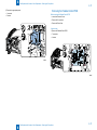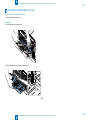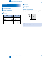
1
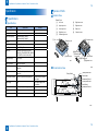
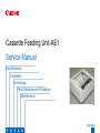
Cassette Feeding Unit-AE1
Service Manual
Specifications
Installation
Technology
Parts Replacement Procedure
Maintenance
F-0-1
1
2
3
4
5
Appendix
Contents
Safety Precautions
Notes Before it Works Serving----------------------------------------------0-2
Specifications
Specification---------------------------------------------------------------------1-2
Specifications------------------------------------------------------------------------ 1-2
Specifications--------------------------------------------------------------------------------- 1-2
Names of Parts---------------------------------------------------------------------- 1-2
External View--------------------------------------------------------------------------------- 1-2
Cross-Section View------------------------------------------------------------------------- 1-2
Installation
How to Check this Installation Procedure---------------------------------- 2
When using the parts included in the package--------------------------------- 2
Symbols in the illustration------------------------------------------------------------ 2
Points to Note at Installation-------------------------------------------------- 2
Checking the Contents--------------------------------------------------------- 3
CST. Feeding Unit-AE1----------------------------------------------------------------------- 3
Contents of Cassette Spacer-A1----------------------------------------------------------- 3
Turning OFF the Host Machine----------------------------------------------- 5
Unpacking-------------------------------------------------------------------------- 5
Installation Procedure----------------------------------------------------------- 6
Setting the Cassette------------------------------------------------------------12
Adjustment------------------------------------------------------------------------13
Adjustment of Margin (1st side)----------------------------------------------------------- 13
Technology
Function--------------------------------------------------------------------------3-2
Basic Configuration----------------------------------------------------------------- 3-2
Sensor / Solenoid---------------------------------------------------------------------------- 3-2
Pickup/Feed System--------------------------------------------------------------- 3-2
Overview--------------------------------------------------------------------------------------- 3-2
Sequence-------------------------------------------------------------------------------------- 3-3
Paper Size Detection----------------------------------------------------------------------- 3-3
Paper level sensor-------------------------------------------------------------------------- 3-5
JAM Detection----------------------------------------------------------------------- 3-7
Delay JAM------------------------------------------------------------------------------------- 3-7
Stationary JAM------------------------------------------------------------------------------- 3-7
Power ON JAM------------------------------------------------------------------------------- 3-7
Door open JAM------------------------------------------------------------------------------- 3-7
Power supply------------------------------------------------------------------------- 3-8
Power connection with each option----------------------------------------------------- 3-8
Parts Replacement Procedure
Parts Replacement------------------------------------------------------------4-2
Remove from the host machine------------------------------------------------Removing the Cassette Feed Roller------------------------------------------Removing the Separation Roller-----------------------------------------------Removing the Pickup Roller-----------------------------------------------------Removing the Pickup Assembly Idler Gear---------------------------------Removing the Cassette 3 Pickup Unit-----------------------------------------
4-2
4-5
4-5
4-6
4-6
4-7
When Connecting to 1-Cassette Unit--------------------------------------------------- 4-8
Removing the Cassette Size Detection Unit--------------------------------4-10
Removing the Pickup Motor-----------------------------------------------------4-10
Removing the Cassette Right Lower Cover---------------------------------4-12
Maintenance
Maintenance---------------------------------------------------------------------5-2
Periodical maintenance----------------------------------------------------------- 5-2
Periodically replacement parts----------------------------------------------------------- 5-2
Consumables--------------------------------------------------------------------------------- 5-2
Adjustment---------------------------------------------------------------------------- 5-2
Margin Adjustment -------------------------------------------------------------------------- 5-2
Parts Configuration / Role----------------------------------------------------------------- 5-4
Appendix
Service Tools--------------------------------------------------------------------6-2
Special Tools------------------------------------------------------------------------- 6-2
General Circuit Diagram (1/3)--------------------------------------------------- 6-3
General Circuit Diagram(2/3)---------------------------------------------------- 6-4
General Circuit Diagram(3/3)---------------------------------------------------- 6-5
Safety Precautions
■ Notes Before it Works Serving
0
Safety Precautions > Notes Before it Works Serving
0-2
Notes Before it Works Serving
Caution
At servicing, be sure to turn off the power source according to the specified steps and
disconnect the power plug.
Caution
Do not turn off the power switch (of the host machine) when downloading is under way.
Turning off the main power switch while downloading is under way can disable the
machine.
0
Safety Precautions > Notes Before it Works Serving
0-2
1
1
Specifications
Specifications
■ Specifications
■ Names of Parts
1
Specifications > Specification > Names of Parts > Cross-Section View
1-2
Specification
Names of Parts
■ External View
Specifications
External Cover
■ Specifications
Item
Specification
Remarks
Paper storage method
Front loading method
Pickup method
Separation retard method
Paper stack capacity
550sheets (80g/m2 paper),
680sheets (64g/m2 paper)
Cassette
2
Paper feed reference
Center reference
Paper Type
64g/m2 ~90g/m2
Paper size
Standard (universal) A3,B4,A4,B5,
LDR,LGL,LTR,A4R,B5R,LTRR, A5R,EX
EC,STMTR,12"x18",8K,16K,16KR
Paper grammage
64 to 90g/m2
Paper size switch
Size auto detection
Control Panel
None (Use the key on the host
machine)
Display
None (Use the key on the host
machine)
Environmental measure
Heater for paper humidity adjustment
Cassette heater is available
as an option
Power supply
No
Option power supply of the
host machine
Size
565(W) - 650(D) - 248(H) [mm]
Weight
27.5kg
Max. power consumption
100W
[1]
Left cover
[6]
Right lower cover
[2]
Upper tray cover
[7]
Right rear cover
[3]
Lower tray cover
[8]
Rear cover
[4]
Right front cover
[9]
Connector cover
[5]
Pedestal right cover
[1]Left cover
[2]Upper tray cover
[9]Connector cover
[4]Right front cover
[5]Cassette right
[3]Lower tray cover
lower cover
[8]Rear cover
[6]Right lower cover
F-1-1
[7]Right rear cover
F-1-2
■ Cross-Section View
Pickup Roller 3
Lifter
Pickup Roller 4
Lifter
Vertical path Roller 3
Feed Roller 3
Detachment Roller 3
Vertical path Roller 4
Feed Roller 4
Detachment Roller 4
T-1-1
F-1-3
1
Specifications > Specification > Names of Parts > Cross-Section View
1-2
2
2
Installation
Installation
■ How to Check this
Installation Procedure
■ Checking the Contents
■ Installation Procedure
■ Adjustment
2
Installation > Points to Note at Installation
How to Check this Installation Procedure
Points to Note at Installation
• In the case of connecting to the 250 Sheets Cassette Model, the Cassette Spacer-A1 is
When using the parts included in the package
required.
A symbol is described on the illustration in the case of using the parts included in the package
of this product.
• To enable function of the heater, "Cst Heater Kit-J1" and "Cassette Heater Unit-37" must be
installed.
Packaged Item
F-2-1
Symbols in the illustration
The frequently-performed operations are described with symbols in this procedure.
Screw
Tighten
Harness
Connector
Remove
Connect
Disconnect
Secure
Free
Claw
Insert
Remove
Push
Plug in
Turn on
Checking instruction
Check
Visual Check
Sound Check
F-2-2
2
Installation > Points to Note at Installation
2
Installation > Checking the Contents
Checking the Contents
■ CST. Feeding Unit-AE1
[1] Cassette Feeding Unit x 1
[2] Positioning Pin x 2
[5] Size Plate x 2
[6] Screw
(RS Tightening; M3X8.5) x 5
[3] Connecting Fixture x 1
< CD/Guides >
[4] Connector Cover x 1
F-2-3
• FCC/IC Sheet
■ Contents of Cassette Spacer-A1
MEMO:
Use the Cassette Spacer-A1 when connecting to the 250 Sheets Cassette Model.
2
Installation > Checking the Contents
2
Installation > Checking the Contents
[1] Cassette Spacer x 1
[2] Positioning Pin (Long) x 2
*; Not use with this procedure.
2
Installation > Checking the Contents
[3] Connecting Fixture x 1
[4] Connector Cover x 1
F-2-4
2
Installation > Unpacking
Turning OFF the Host Machine
Turn OFF the main power switch on the host machine, and then remove the power plug from the outlet.
Unpacking
1)Remove the container box.
2)Open the plastics, and remove the 2 pads by lifting the rear side of the
equipment. Then, move the plastics toward the pads at the front side.
Plastic
3)Remove the 2 remaining pads and the plastics by lifting the front side
of the equipment.
Pad
Pad
Pad
Plastic
F-2-5
4)Lift the equipment and unload it from the pallet.
Pad
F-2-6
5)Remove all tapes affixed on the outside of the equipment.
6)Remove the all tapes on the cassette and packing materials.
F-2-7
2
Installation > Unpacking
2
Installation > Installation Procedure
Installation Procedure
MEMO:
Be sure to execute the following step 1) to 3) only when connecting with the 250-sheet cassette model.
1)When connecting with the 250-sheet cassette model, loosen the 2 Positioning Pins which were installed to the Cassette Feeding Unit. (The removed Positioning Pins are no longer used.)
• 4 Screws (The removed screw will be used in step 2).)
x2
x2
F-2-8
2)Install the 2 Positioning Pins (Long) packaged with Cassette Spacer-A1.
• 4 Screws (Use the screws removed in step 1).)
x2
x2
F-2-9
2
Installation > Installation Procedure
2
Installation > Installation Procedure
3)When connecting to the 250 Sheets Cassette Model, install the
Cassette Spacer included in the Cassette Spacer-A1 by inserting it
into the 2 Positioning Pins.
4)In the case that the Cassette Module (1- Cassette Unit) is
installed, remove it with a flat-blade screwdriver.
5)In the case that the Grip Covers are installed, release the claws
with a flat-blade screwdriver and remove the Grip Covers.
Positioning Pin
Claw
Claw
Claw
Positioning Pin
F-2-11
F-2-10
F-2-12
6)Open the Right Lower Cover of the Cassette Feeding Unit.
7)Hold the 4 Grips on the host machine, and mount the host machine while aligning the right and left corners of the front of the host machine and the front of the Cassette
Feeding Unit.
CAUTION:
Grip
• When mounting the host machine on the
Grip
8)Close the Cassette Right Lower
Cover.
9)Remove the cassettes to which
the Connecting Fixture will be
installed in a later step.
equipment, be sure to fit the holes on
the bottom of the host machine into the 2
Positioning Pins on the top of the equipment.
• The host machine weighs maximum approx.
50 to 79 kg.
It is recommended to lift it with 2 people
or more. However, if there is a standard to
handle a heavy load in each sales company,
follow it for operation.
Also, make sure to lift the machine with
keeping it level at operation.
2
Installation > Installation Procedure
F-2-13
2
Installation > Installation Procedure
10)Install the Connecting Fixture.
• 1 Screw (RS Tightening; M3 x 8.5)
< When Connecting to 550 Sheets Cassette Model >
• To install the Connecting Fixture, insert it into the hole on
the host machine and hook the tab of it to the plate on the
host machine.
Screw
F-2-14
< When Connecting to 250 Sheets Cassette Model >
• To install the Connecting Fixture, insert it included in the
Cassette Spacer-A1 into the hole on the host machine,
and hook the tab of it to the plate on the host machine.
Screw
F-2-15
< When Connecting to Cassette Module (1- Cassette Unit) >
F-2-16
2
Installation > Installation Procedure
2
Installation > Installation Procedure
11) Remove the Connector Cover. (The removed cover will not be used.)
• 1 Screw (The removed screw will be used in step 14).)
< In the Case of Host Machine >
< In the Case of Cassette Module (1- Cassette Unit) >
F-2-17
F-2-18
12)Put the 3 cables of the Cassette Feeding Unit through the guide, and connect the 3 connectors to the host machine.
MEMO:
Connect the connector with black color tube to "Cst Heater Kit-J1" (option).
CAUTION:
• When securing the 3 cables in place with the guide, be sure to place one
cable to one groove of the guide.
• Be sure to tuck the extra slack of the cable to the host machine side.
< When Connecting to 550 Sheets Cassette Model >
< When Connecting to 250 Sheets Cassette Model >
< When Connecting to Cassette Module (1- Cassette Unit) >
x3
x3
x3
x3
x3
x3
F-2-19
2
Installation > Installation Procedure
F-2-20
F-2-21
2
Installation > Installation Procedure
10
13) Loosen the screw on the Connector Cover included in the package, and install the grounding wire between it and the toothed washer.
Screw
Round Shape
Terminal
Toothed Washer
F-2-22
CAUTION:
• Be sure to pay attention to
the installation orientation
of the grounding wire.
• Install from the direction of
the arrow marked on the
Plate
F-2-23
2
Installation > Installation Procedure
10
2
Installation > Installation Procedure
11
14)Install the Connector Cover.
• 1 Screw (Use the screw removed in step 11).)
< When Connecting to Host Machine >
CAUTION:
< When Connecting to Cassette Module (1- Cassette Unit) >
Be sure not to trap the cable.
x2
F-2-24
F-2-25
15)Turn the 4 Adjusters clockwise 4 times, and secure the equipment in place firmly.
16)Install the removed covers.
• Grip Cover
• Right Lower Sub Cover (In the case that the Cassette
Module (1- Cassette Unit) is installed.)
17)Return the cassette of the host machine.
18)Plug the power plug of the host machine to the
outlet.
19)Turn ON the main power switch.
F-2-26
2
Installation > Installation Procedure
11
2
Installation > Setting the Cassette
12
Setting the Cassette
1)Hold the Side Guide Plate Lever and set the Side Guide Plate to
the specified size.
At this time, set the Side Guide Plate to the click position (the
position where you feel a click) by moving the Side Guide Plate
while using the size index (label) of the sheet size to be set as a
measure.
3)Set papers.
4)Open the cover at the Size Plate insertion area.
Side Guide Plate
Trail Edge Guide Plate Lever
Side Guide Plate Lever
Paper
Cover
2)Hold the Trailing Edge Guide Plate Lever and set the Trailing
Edge Guide Plate to the specified size.
At this time, set the Trailing Edge Guide Plate to the click position
(the position where you feel a click) by moving the Trailing Edge
Guide Plate while using the size index (label) of the sheet size to
be set as a measure.
Trail Edge Guide Plate
F-2-27
F-2-28
5)Cut the 2 places of the Size Plates with nippers.
6)Insert the Size Plate in accordance with the paper size being set.
(Lump the Size Plates not in use together and store them at the
rear.)
Cut
7)Close the cover at the Size Plate insertion area, and return
the cassette to the equipment.
MEMO:
The paper size setting is recognized automatically.
F-2-29
F-2-30
2
Installation > Setting the Cassette
12
2
Installation > Adjustment
13
Adjustment
■ Adjustment of Margin (1st side)
MEMO:
As for the adjustment method, the same procedure is applied to the Cassette
3 and 4.
2)Pull out the cassette.
3)Check the 2 scale positions of the Adjustment Plate.
1)Make a copy from the Cassette 3 and 4, and check that the left edge margin is 2.5+/-1.5mm.
Feed direction
of paper
L1
image
F-2-31
MEMO:
In the case of out of specification, execute step 2) through 8) indicated below.
F-2-32
4)Loosen the 3 Fixation Screws.
F-2-33
2
Installation > Adjustment
13
3
3
Technology
Technology
■ Basic Configuration
■ Pickup/Feed System
■ JAM Detection
■ Power supply
3
Technology > Function > Pickup/Feed System > Overview
3-2
Function
Pickup/Feed System
■ Overview
Basic Configuration
Papers in the cassette are lifted up with the Lifter Plate.
■ Sensor / Solenoid
Cassette 3
paper presence sensor(PS2)
Cassette 3
pickup solenoid(SL1)
At pickup, the Pickup Roller picks up a paper by coming down and contact with paper surface.
The Pickup Roller comes down when the Pickup Solenoide turns ON.
A paper picked up by the Pickup Roller is fed to the feed path with the Separation Roller, and
Cassette 3 Retry sensor(PS8)
then, is fed to the Registration Roller with the Vertical Path Roller.
Cassette 4 Retry sensor(PS9)
The Vertical Path Roller, Pickup Roller, Feed Roller and Separation Roller are driven by the
Cassette Pickup Motor.
Cassette 3
paper level sensorA(PS4)
Vertical path Roller 3
Pickup Roller 3
Cassette 3
paper level sensor B(PS5)
Cassette 4
pickup solenoid(SL2)
Feed Roller 3
Separation Roller 3
Lifter
Cassette 4
paper level sensor B(PS7)
Cassette 4
Cassette 4
paper presence sensor(PS3)
paper level sensor A(PS6)
Cassette 3 pickup motor(M1)
Pedestal controller
Cassette 3 pickup motor(M2)
PCB(UN1)
SL1
M1
Pickup Roller 4
Lifter
SL2
Vertical path Roller 4
Feed Roller 4
Separation Roller 4
M2
Pedestal right cover sensor(PS1)
Cassette 3 size
switch A(SW1)
Cassette 3 size
switch B(SW2)
F-3-2
Cassette 4 size
switch A(SW3)
Cassette 4 size
switch B(SW4)
Cassette heater(H1)
F-3-1
3
Technology > Function > Pickup/Feed System > Overview
3-2
3
Technology > Function > Pickup/Feed System > Paper Size Detection
■ Sequence
■ Paper Size Detection
At the cassette pickup assembly, since the feed speed is increased, detection cannot catch
Print
start
up with it. Thus, delay and stationary jam detection are not executed at the Cassette 1 Pre-
Cassette
pedistal
PRINT
Connect in device
3-3
Registration Sensor. Instead of it, the Vertical Path Sensor executes the delay and stationary
jam detection. Since the residual jam should be detected on each cassette, the Cassette 1
Cassette 3 pickup motor
(M1)
Cassette 3 pickup
solenoid(SL1)
Cassette 3 retry sensor
(PS8)
Cassette 1 pickup motor
(M3)
Vertical path sensor
(UN53)
Registration sensor
(PS33)
Registration clutch
(CL33)
Inner derivery sensor
(PS37)
First derivery motor
(M22)
First derivery sensor
(PS34)
Registration motor
(M19)
Fixing motor
(M21)
Pre-Registration Sensor detects it. Because the Vertical Path Sensor is too close and it is
unnecessary to execute detection, the Vertical Path Sensor does not execute residual jam
detection.
Cassette 3 size switch B[SW2]
Cassette 3 size switch A [SW1]
: Cassette 3: The speed of pickup increases
F-3-3
Print
start
Connect in device
Cassette
pedistal
PRINT
Cassette 4 pickup motor
(M2)
Cassette 4 pickup
solenoid(SL2)
Cassette 4 retry sensor
(PS9)
Cassette 1 pickup motor
(M3)
Vertical path sensor
(UN53)
Registration sensor
(PS33)
Registration clutch
(CL33)
Inner delivery sensor
(PS37)
First delivery motor
(M22)
First delivery sensor
(PS34)
Registration motor
(M19)
Fixing motor
(M21)
Cassette 4 size switch A[SW3]
Cassette 4 size switch B[SW4]
F-3-5
: Cassette 4: The speed of pickup increases
F-3-4
3
Technology > Function > Pickup/Feed System > Paper Size Detection
3-3
3
Technology > Function > Pickup/Feed System > Paper Size Detection
3-4
Cassette size
switch A
Width
Rear detection
rink
B5
EXEC
16K
A5-R
A4
STMT-R
LTR
B5-R
LTR-R
A4-R
LGL
B4
8K
A3
LDR
12x18
Rear guide plate
Detection dial
Cassette size
switch B
257.0
267.0
270.0
148.5
297.0
139.7
279.4
182.0
215.9
210.0
215.9
257.0
270.0
297.0
279.4
304.8
Length
182.0
184.0
195.0
210.0
210.0
215.9
215.9
257.0
279.4
297.0
355.6
364.0
390.0
420.0
431.8
457.2
1
0
0
0
ON
0
ON
0
ON
0
0
0
0
0
0
0
0
Width detection
2
3
ON
ON
ON
0
ON
0
ON
0
0
0
0
ON
ON
ON
ON
ON
ON
ON
ON
ON
0
ON
ON
ON
ON
ON
ON
ON
ON
0
ON
0
4
1
0
0
0
0
0
0
0
0
0
0
0
0
0
0
0
0
0
0
ON
ON
ON
ON
ON
0
ON
0
ON
ON
ON
0
0
0
Length detection
2
3
0
0
0
ON
ON
ON
ON
ON
0
ON
ON
ON
ON
0
0
0
0
0
0
0
0
0
0
ON
0
ON
0
ON
ON
ON
ON
0
4
0
0
0
0
0
0
0
ON
ON
0
ON
0
ON
ON
ON
ON
T-3-1
Also, the cassette presence is detected when the size switch is pushed. (If no switch is
pushed, it is determined as no cassette.))
Side guide plate
Detection dial
Cassette size switch B
F-3-6
3
Technology > Function > Pickup/Feed System > Paper Size Detection
3-4
3
Technology > Function > Pickup/Feed System > Paper level sensor
3-5
● Setting method when the size detection patterns are overlapped
Size should be found manually on the check screen for the combination of A5-Rand STMT-R
or the combination of B5-R and EXEC.
Specify the ecognition method for the special paper with user setting.
■ Paper level sensor
Paper level in a cassette is detected with the sensor indicated below.
Cassette 3
Cassette 4
The setting size is indicated below.
Cassette paper level sensor A
PS4
PS6
Cassette paper level sensor B
PS5
PS7
Related Service Mode
Cassette paper sensor
PS2
PS3
COPIER> OPTION> CST> CSTX-UY> Nomber
Cassette paper sensor(PS2)
X shows Cassette Number. Y shows size category. (X, Y is one of the number 1/2/3/4.)
No.
U1
U2
U3
U4
Lifter latch
Size
Cassette
paper level sensor A(PS4)
OFI, E-OFI, M-OFI, A-OFI, FLSP, A-FLSP, A-LTRR, FA4, G-LGL
G-LTR-R, K-LGL-R
K-LGL, G-LTR, A-LTR
B-OFI
T-3-2
No.
22
23
24
25
27
28
29
30
31
32
33
34
36
37
42
T-3-4
Flag
Cassette
paper level sensor B(PS5)
Size
K-LGL
K-LGLR
FLSC
A-FLS
E-OFI
B-OFI
A-LTR
A-LTRR
G-LTR
G-LTRR
A-LGL
G-LGL
A-OFI
M-OFI
FA4
Paper sensor flag
Lifter gear
T-3-3 in the Cassette 3,
Sample: When setting A_LTR
COPIER> OPTION> CST> CST3-U3>29
Tray
F-3-7
3
Technology > Function > Pickup/Feed System > Paper level sensor
3-5
3
Technology > Function > Pickup/Feed System > Paper level sensor
If the paper is full
3-6
Cassette paper level sensor A
Cassette paper level sensor B
Paper
Paper level
sensor B
Paperl
sensor
Paper level
Display
OFF
OFF
OFF
100% to 50%
ON
OFF
OFF
50% to 50 sheets
F-3-9
ON
ON
OFF
50 sheet or less
F-3-10
---
---
ON
no paper
F-3-11
F-3-12
OFFOFF
If the paper is approx. half
Paper level
sensor A
Cassette paper level sensor A
T-3-5
Paper
Cassette paper level sensor B
OFFON
If the paper is a little
Cassette paper level sensor A
Paper
Cassette paper level sensor B
ONON
If the paper is absent
Cassette paper Presence sensor
Fulg
Paper tray
F-3-8
3
Technology > Function > Pickup/Feed System > Paper level sensor
3-6
3
Technology > Function > JAM Detection > Door open JAM
3-7
JAM Detection
■ Stationary JAM
In case that the corresponding sensor is not turned ON within the specified time after it is
■ Delay JAM
In case that the leading edge of paper does not reach to the sensor within the specified time
turned ON.
Start key ON
or
Print start
after the speed of Cassette 3 and 4 Pickup Motor decreases to half.
Start key ON
or
Print start
INTR
INTR
[1]
Pickup motor
normal
Sensor/PS8/PS9
PRINT
Jam check
[1]
[2]
Jam check
/
:Motor speed up
Sensor/PS8/PS9
[2]
/
PRINT
L
L+A
normal
error
(L = Paper length feed range A = Provision feed range)
F-3-14
error
Sensor
Cassette 3 retry sensor (PS8)
[1]:Provision feed time
[2]:Jam margin
F-3-13
Cassette
Motor
Sensor
Cassette 3
Cassette 3 pickup motor
(M1)
Cassette 3 retry sensor (PS8)
Cassette 4
Cassette 4 pickup motor
(M2)
Cassette 4 retry sensor (PS9)
Cassette 4 retry sensor (PS9)
T-3-7
■ Power ON JAM
Before starting the warm-up rotation at power ON, check that no paper is at the sensor
indicated below.
Sensor
Cassette 3 retry sensor (PS8)
T-3-6
Cassette 4 retry sensor (PS9)
T-3-8
■ Door open JAM
When it is detected that the door is opened during copy and printing.
Sensor
Pedestal right cover sensor(PS1)
T-3-9
3
Technology > Function > JAM Detection > Door open JAM
3-7
3
Technology > Function > Power supply > Power connection with each option
Power supply
3-8
When power is turned ON, the connected equipment supplies 24VDC and 5VDC to the
Pedestal Controller PCB.
■ Power connection with each option
25VDC generates 3.3VDC in 3-Terminal Regulator in the Pedestal Control PCB, 5VDC is
Indicating the power supply path between the Printer and Option.
used for sensors and IC driver and the 3.3VDC is used for the Control IC (Asic)
Reader / ADF Unit
Connect in device
Pedistal controller PCB
+24V
Controller Power
Suplly PCB
Built-in Wiring
+5V
FU1
Solenoid
FU3
Motor
FU2
3 Terminal
Regulator
+3.3V
Inner finisher-B1
ASiC
Sensor
Motor Driver
Cassette pedestal Unit-W1
F-3-16
Cassette pedestal Unit-AE1
Connector inside the cover is used for the connection with the printer.
3
F-3-15
Technology > Function > Power supply > Power connection with each option
3-8
4
Parts
Replacement
Procedure
■ Remove from the host
machine
■ Removing the Cassette
Feed Roller
■ Removing the Separation
Roller
■ Removing the Pickup Roller
■ Removing the Pickup
Assembly Idler Gear
■ Removing the Cassette 3
Pickup Unit
4
Parts Replacement Procedure
■ Removing the Cassette Size
Detection Unit
■ Removing the Pickup Motor
■ Removing the Pedestal
Controll PCB
■ Removing the Cassette
Right Lower Cover
4
Parts Replacement Procedure > Parts Replacement > Remove from the host machine
Parts Replacement
4-2
How to remove
1)Remove the 3 harness from the guides
<When Connecting to 550 Sheets Cassette Model>
Remove from the host machine
Before removing the host machine
x3
• Remove the Connecter Cover
<In the Case of Host Machine>
x3
F-4-3
<When Connecting to 250 Sheets Cassette Model>
x3
F-4-1
<In the Case of 1-Cassette Unit>
x3
F-4-4
F-4-2
4
Parts Replacement Procedure > Parts Replacement > Remove from the host machine
4-2
4
Parts Replacement Procedure > Parts Replacement > Remove from the host machine
<When Connecting to 1- Cassette Unit>
4-3
2)Remove the Cassette
3)Remove the Connecting Fixture
• 1-screw
< When Connecting to 550 Sheets Cassette Mode>
x3
x3
F-4-5
screw
F-4-6
4
Parts Replacement Procedure > Parts Replacement > Remove from the host machine
4-3
4
Parts Replacement Procedure > Parts Replacement > Remove from the host machine
< When Connecting to 250 Sheets Cassette Mode>
4-4
< When Connecting to 1-Cassette Unit>
screw
4) Lift and remove the host machine
F-4-8
CAUTION:
•
The host machine weighs maximum approx. 50 to 79 kg.It is recommended to lift it with
2 people or more. However, if there is a standard to handle a heavy load in each sales
company, follow it for operation.Also, make sure to lift the machine with keeping it level at
operation.
Grip
Grip
F-4-7
5)Install the cassette 3 and cassette 4
4
Parts Replacement Procedure > Parts Replacement > Remove from the host machine
4-4
4
Parts Replacement Procedure > Parts Replacement > Removing the Separation Roller
Removing the Cassette Feed Roller
4-5
Removing the Separation Roller
Before removing the Cassette Feed Roller
Before removing the Separation Roller
• Remove the Cassette
• Remove the Cassette
MEMO:
This procedure describes the removing steps of cassette 1 Feed Roller. Go through the
same procedure for the Feed Roller of cassette 3 and cassette 4.
How to remove
MEMO:
This procedure describes the removing steps of cassette 1 Separetion Roller. Go
through the same procedure for the Separetion Roller of cassette 3 and cassette 4.
Note:
Do not touch the surface of Pickup Roller, Feed Roller and the Separation Roller.
Note:
Do not touch the surface of Pickup Roller, Feed Roller and the Separation Roller.
How to remove
1)Remove the Cassette Feed Roller.
• 1 tab
1)Removing the Separation Roller
• 1 tab
F-4-9
F-4-10
4
Parts Replacement Procedure > Parts Replacement > Removing the Separation Roller
4-5
4
Parts Replacement Procedure > Parts Replacement > Removing the Pickup Assembly Idler Gear
Removing the Pickup Roller
4-6
Removing the Pickup Assembly Idler Gear
Before removing the Cassette Pickup Roller
Before removing the Pickup Assembly Idler Gear
• Remove the Cassette
• Remove the Cassette
• Remove the Pickup Roller
• Remove the Feed Roller
How to remove
How to remove
MEMO:
This procedure describes the removing steps of cassette 1 Pickup Roller. Go through
the same procedure for the Pickup Roller of cassette 3 and cassette 4.
MEMO:
This procedure describes the removing procedure of cassette 1 Pickup Assembly Idler
Gear. Go through the same procedure for the Pickup Assembly Idler Gear of cassette 3
and cassette 4.
Note:
Do not touch the surface of Pickup Roller, Feed Roller and the Separation Roller.
Note:
Do not touch the surface of Pickup Roller, Feed Roller and the Separation Roller.
1)Removing the Pickup Roller
• 1 pin
• 1 tab
1)Remove the Pickup Assembly Idler Gear.
• 1 tab
F-4-11
4
Parts Replacement Procedure > Parts Replacement > Removing the Pickup Assembly Idler Gear
F-4-12
4-6
4
Parts Replacement Procedure > Parts Replacement > Removing the Cassette 3 Pickup Unit
Removing the Cassette 3 Pickup Unit
Before removing the Cassette 3 Pickup Unit
4-7
4) Remove the Right Front Cover of the Cassette Feeding Unit.
• 1 screw
1) Open the Cassette Right Lower Cover of the Cassette Feeding Unit.
F-4-13
2) Pull out cassette.
3)Remove the Right Front Cover of the Host Machine.
• Remove the claw with a flat-blade screwdriver and remove the Right Front Cover.
• 1 screw
• 1 claw
Claw
4
Parts Replacement Procedure > Parts Replacement > Removing the Cassette 3 Pickup Unit
4-7
4
Parts Replacement Procedure > Parts Replacement > Removing the Cassette 3 Pickup Unit > When Connecting to 1-Cassette Unit
4-8
■ When Connecting to 1-Cassette Unit
5)Remove the Right Rear Cover of the Host Machine.
• Remove the claw with a flat-blade screwdriver and remove the Right Rear Cover.
• 1 screw
MEMO :
When Connecting to 1-Cassette Unit, be sure to remove the Cassette Right Lower
Cover.
Claw
1) Remove the Cassette Right Lower Cover of the 1-Cassette Unit.
D-cut
2) Remove the Right Front Cover of the Host Machine and remove Right Front Cover of the
1-Cassette Unit
F-4-14
6) Remove the Right Rear Cover of the 2-Cassette Unit.
• 1 screw
• 1 screw
Projection
4
Hook
F-4-16
Pin
F-4-15
Parts Replacement Procedure > Parts Replacement > Removing the Cassette 3 Pickup Unit > When Connecting to 1-Cassette Unit
4-8
4
Parts Replacement Procedure > Parts Replacement > Removing the Cassette 3 Pickup Unit > When Connecting to 1-Cassette Unit
3) Remove the Right Rear Cover of the Host Machine and remove Right Rear Cover of the
4-9
How to remove
1-Cassette Unit
MEMO:
This procedure describes the removing procedure of Cassette 3 Pickup Assembly. Go
through the same procedure for the Cassette 4 Pickup Assembly.
• Remove the Right Front Cover
• 1 screw
1)
Remove the Sensor Unit.
• 1 screw
• 1 connector
• 1 harness guide
Connector
Sensor Unit
Hook
Pin
Harness Guide
F-4-17
F-4-18
2)Remove the cassette 3 Pickup Unit
• 4 screws
x4
F-4-19
4
Parts Replacement Procedure > Parts Replacement > Removing the Cassette 3 Pickup Unit > When Connecting to 1-Cassette Unit
4-9
4
Parts Replacement Procedure > Parts Replacement > Removing the Pickup Motor
Removing the Cassette Size Detection Unit
4-10
Removing the Pickup Motor
Before removing the Cassette Size Detection Unit
Before removing the Pickup Motor
• Remove the Right Front Cover
• Remove the Right Rear Cover
• Remove the Cassette Pickup Unit
• Remove the Connector Cover
• Remove 5 connectors
• Remove Rear Cover
• 4 screws
• 2 hooks
How to remove
MEMO:
This procedure describes the removing steps of Cassette 3 Size Detection Unit. Go
through the same procedure for Cassette 4 Size Detection Unit.
x3
1) Remove the Cassette 3 Size Detection Unit
• 1 connector
• 1 wire saddle
• 2 screws
Hook
Hook
F-4-21
How to remove
MEMO:
This procedure describes the removing step of cassette 3 Pickup motor. Go through the
same procedure for the Pickup motor of cassette 4.
x2
Cassette 3 Size Detection Unit
Connector
Wire Saddle
F-4-20
4
Parts Replacement Procedure > Parts Replacement > Removing the Pickup Motor
4-10
4
Parts Replacement Procedure > Parts Replacement > Removing the Pickup Motor
4-11
Removing the Pedestal Controll PCB
1)Remove the upper pickup motor.
• 1 connector
• 3 screws
Before removing the Pedestal Controll PCB
• remove the Connector Cover
• Remove the 5 connectors
• Remove the Rear Cover
How to remove
1)Remove the Pedestal Controll PCB
• 7 connectors
• 4 screws
x3
x7
x4
F-4-22
F-4-23
4
Parts Replacement Procedure > Parts Replacement > Removing the Pickup Motor
4-11
4
Parts Replacement Procedure > Parts Replacement > Removing the Cassette Right Lower Cover
4-12
Removing the Cassette Right Lower Cover
Before removing the Cassette Right Lower Cover
• Open the cassette right lower cover
How to remove
1)Lift up lower guide and remove the arm
F-4-24
2)Fit the D-cut and remove the cassette right lower cover
D-cut
F-4-25
4
Parts Replacement Procedure > Parts Replacement > Removing the Cassette Right Lower Cover
4-12
5
Maintenance
■ Periodical maintenance
■ Adjustment
■ Parts Configuration / Role
5
Maintenance
5
Maintenance > Maintenance > Adjustment > Margin Adjustment
Maintenance
5-2
Adjustment
■ Margin Adjustment
Periodical maintenance
● First side; Mechanical Adjsutment
■ Periodically replacement parts
1) Make copies using the Cassette 3 and 4, and check that the left edge margin is 2.5±1.5mm.
N/A
■ Consumables
Parts
Number
Num
Interval
Pickup roller
FB6-3405
1
120k
Feeding roller
FC6-7083
1
120k
Separation roller
FC6-6661
1
120k
Pickup idler gear
FU3-0280
1
120k
Remarks
For China only
Flying Paper
T-5-1
5
image
L1
Parts Name
Feed direction
of paper
Maintenance > Maintenance > Adjustment > Margin Adjustment
MEMO:
Adjsutment method is same for both the Cassette 3 and 4.
F-5-1
5-2
5
Maintenance > Maintenance > Adjustment > Margin Adjustment
5-3
2) Pull out the cassette.
3) Check the 2 scale positions on the adjusting plates.
6) Tighten the fixing screw.
F-5-2
7) Return the cassette to its original position.
MEMO:
When the cassette positions are uneven due to the mechanical adjustment, adjust them
by loosening the screw at left side.
4) Loosen the 3 fixing screws.
F-5-3
8) Make copies using the Cassette 3 and 4, and check that the left edge margin is 2.5±1.5mm.
5) Move the adjusting plates back and forth by referring the scale checked in the step 2. As
moving the adjusting plate toward the rear by 1 scale, the left edge margin becomes 1mm
smaller.
MEMO:
When moving the scale, be sure that the amount of the value to be moved are the same
for the 2 points.
5
Maintenance > Maintenance > Adjustment > Margin Adjustment
5-3
5
Maintenance > Maintenance > Adjustment > Parts Configuration / Role
Parts Configuration / Role
Cassette 3
paper presence sensor(PS2)
■ Parts Configuration / Role
Mark
Name
Part No.
M1
Cassette 3 pickup motor FK2-7327
M2
Cassette 4 pickup motor FK2-7327
PS4 Cassette 3 paper level
sensor A
PS5 Cassette 3 paper level
sensor B
PS8 Cassette 3 retry sensor
FK2-0149
FK2-0149
FK2-0149
PS2 Cassette 3 paper sensor FK2-0149
PS6 Cassette 4 paper level
sensor A
PS7 Cassette 4 paper level
sensor B
PS9 Cassette 4 retry sensor
FK2-0149
FK2-0149
FK2-0149
PS3 Cassette 4 paper sensor FK2-0149
PS1 Pedestal right cover
sensor
SL1 Cassette 3 pickup
solenoid
SL2 Cassette 4 pickup
solenoid
SW1 Cassette 3 size switch A
FH7-7312
FK2-0408
FK2-0408
WC2-5680
SW2 Cassette 3 size switch B WC2-5680
SW3 Cassette 4 size switch A WC2-5680
SW4 Cassette 4 size switch B WC2-5680
H1 Cassette heater
FH7-4742
UN1 Pedestal controller PCB FH4-2531
5-4
Role
Drive the pickup unit
3
Drive the pickup unit
4
Detects the cassette
3 paper level
Detects the cassette
3 paper level
Cassette 3 Retry
Detection
Detects whether
paper is loaded in the
cassette 3
Detects the cassette
4 paper level
Detects the cassette
4 paper level
Cassette 4 Retry
Detection
Detects whether
paper is loaded in the
cassette 4
Detects the right
cover open
controll the cassette
3 pickup timing
controll the cassette
4 pickup timing
Detects the cassette
3 paper size
Detects the cassette
3 paper size
Detects the cassette
4 paper size
Detects the cassette
4 paper size
FUNCTION
Pedestal
>PARTcontroller PCB
CHK
J3006
J3007
Cassette 3
pickup solenoid(SL1)
Cassette 3 Retry sensor(PS8)
Cassette 4 Retry sensor(PS9)
Cassette 3
paper level sensorA(PS4)
Cassette 3
paper level sensor B(PS5)
Cassette 4
pickup solenoid(SL2)
Cassette 4
paper level sensor B(PS7)
J3003
Cassette 4
Cassette 4
paper presence sensor(PS3)
paper level sensor A(PS6)
Cassette 3 pickup motor(M1)
Pedestal controller
Cassette 3 pickup motor(M2)
PCB(UN1)
J3003
J3003
J3003
Cassette 3 size
switch A(SW1)
J3004
Pedestal right cover sensor(PS1)
Cassette 3 size
switch B(SW2)
J3004
J3004
J3004
Cassette 4 size
switch A(SW3)
J3003
J3003
Cassette 4 size
switch B(SW4)
J3004
J3003
J3003
Cassette heater(H1)
J3004
F-5-4
J3004
Controll the cassette
pedestal
T-5-2
5
Maintenance > Maintenance > Adjustment > Parts Configuration / Role
5-4
6
Appendix
■ Service Tools
■ General Circuit Diagram
(1/3)
■ General Circuit
Diagram(2/3)
■ General Circuit
Diagram(3/3)
6
Appendix
6
Appendix > Service Tools > Special Tools
6-2
Service Tools
Special Tools
In addition to the standard tools set, the following special tools are required when servicing the machine:
Tool name
Digital multimeter
Tool No.
Ctgr
FY9-2002
A
Appearance
Remarks
Used as a probe extension when making electrical checks.
T-6-1
Reference: Category
A: Must be kept by each service engineer.
B: Must be kept by each group of about five engineers.
C: Must be kept by each warkshop
6
Appendix > Service Tools > Special Tools
6-2
6-3
9
8
7
6
5
4
3
2
1
F
Appendix > Service Tools > General Circuit Diagram (1/3)
10
F
UN1
Pedestal controller PCB
J3004
1
2
3
4
5
6
7
8
9
10
11
12
13
14
15
16
17
18
19
20
21
22
23
24
25
26
27
28
29
30
31
+5V
GND
CST4_PICKUP_SL
PEDE_DOOR_SNS
+5V
+24V
GND
CST4_LEVEL_B_SNS
CST4_RETRY_SNS
+5V
GND
+5V
GND
CST4_LEVEL_A_SNS
+5V
GND
CST3_PICKUP_SL
CST4_PAPER_SNS
+24V
+5V
GND
CST3_RETRY_SNS
CST3_LEVEL_B_SNS
CST3_LEVEL_A_SNS
+5V
GND
+5V
+5V
GND
E
GND
E
CST3_PAPER_SNS
Appendix > Service Tools > General Circuit Diagram (1/3)
General Circuit Diagram (1/3)
D
D
J1D
J1LH
14
13
12
11
10
1
2
3
4
5
8
9
6
7
7
6
8
9
5
4
3
2
1
14
13
12
11
10
10
11
12
13
14
1
2
3
4
5
9
6
8
7
7
6
8
9
J2D
5
4
3
2
1
10
11
12
13
14
J2LH
J2L
J1L
C
C
J3
3
2
1
J109D
J109DH
J104D
B
J100
J101
J103
J102
J104L
3
1
2
3
2
1
2
3
2
1
3
2
1
3
2
1
1
3
2
1
3
2
1
3
2
1
1
1
J105
2
J106
3
2
1
J107
3
2
1
J108
3
2
1
1
3
2
PS2
PS4
PS5
Cassette 3
paper level
sensor A
Cassette 3
paper level
sensor B
2
1
2
1
B
PS1
J109L
Pedestal right cover sensor
3
2
2
1
3
2
1
3
2
1
3
2
1
1
PS8
SL2
Cassette 3
retry sensor
Cassette 3
pickup
solenoid
2
SL
SL
Cassette 3
paper sensor
3
1
2
J104DH
PS3
Cassette 4
paper sensor
PS6
PS7
Cassette 4
paper level
sensor A
Cassette 4
paper level
sensor B
PS9
SL3
Cassette 4
retry sensor
Cassette 4
pickup solenoid
A
A
Cassette 3
10
9
8
Cassette 4
7
6
5
4
3
2
1
P.1
F-6-1
6-3
6-4
9
8
7
6
5
4
3
2
1
F
Appendix > Service Tools > General Circuit Diagram(2/3)
10
F
UN1
Pedestal controller PCB
E
E
9
10
11
12
13
14
15
16
17
18
19
21
20
J3007
1
2
3
4
1
2
3
4
CST4_B*
8
CST4_B
7
CST4_A*
6
CST3_B*
5
CST3_B
4
CST3_A*
3
CST3_A
J3006
2
CST4_SIZE_0
CST4_SIZE_1
CST4_SIZE_2
CST_SIZE_PWR_ON
CST4_SIZE_3
CST4_SIZE_4
CST4_SIZE_5
CST4_SIZE_6
CST_SIZE_PWR_ON
CST4_SIZE_7
CST3_SIZE_0
CST3_SIZE_1
CST3_SIZE_2
CST_SIZE_PWR_ON
CST3_SIZE_3
CST3_SIZE_4
CST3_SIZE_5
CST3_SIZE_6
D
CST_SIZE_PWR_ON
N.C.
1
CST4_A
J3005
CST3_SIZE_7
Appendix > Service Tools > General Circuit Diagram(2/3)
General Circuit Diagram(2/3)
D
C
C
J8D
J5D
J5LH
11
10
9
8
7
6
5
4
3
2
1
11
10
1
2
3
4
5
6
7
8
9
10
11
1
2
9
3
8
4
7
5
6
6
5
7
4
3
9
8
2
1
10
11
J8LH
J8L
J5L
J12
J11
6
5
4
3
2
1
1
2
3
4
5
6
6
1
M
5
2
4
3
3
4
2
5
1
6
M
M1
M2
Cassette 3 pickup motor
Cassette 4 pickup motor
B
B
J6
J7
5
4
3
2
1
5
SW7
4
3
2
1
5
SW6
Cassette 3
size switch B
4
3
2
1
J9
5
SW9
Cassette 3
size switch A
4
3
2
1
J10
SW8
Cassette 4
size switch B
Cassette 4
size switch A
A
A
10
9
8
7
6
5
4
3
2
1
P.2
F-6-2
6-4
Appendix > Service Tools > General Circuit Diagram(3/3)
Appendix > Service Tools > General Circuit Diagram(3/3)
6-5
General Circuit Diagram(3/3)
F-6-3
6-5