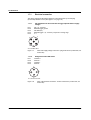
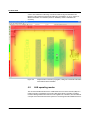
1
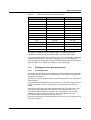
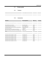
User manual UM EN FL WLAN EPA (5N) Hardware and software for the WLAN Ethernet port adapter versions with 2.4 GHz or 5 GHz and with external antenna connection User manual Hardware and software for the WLAN Ethernet port adapter versions with 2.4 GHz or 5 GHz and with external antenna connection 2012-08-09 Designation: UM EN FL WLAN EPA (5N) Revision: 01 Order No.: — This user manual is valid for: 80998099 Designation Revision FL WLAN EPA Hardware version 2692791 2.1 or later/ firmware version 2.2 or later FL WLAN EPA 5N Hardware version 2700488 2.1 or later/ firmware version 2.2 or later FL WLAN EPA RSMA Hardware version 2701169 2.1 or later/ firmware version 2.2 or later PHOENIX CONTACT Order No. 8099_en_01 Please observe the following notes User group of this manual The use of products described in this manual is oriented exclusively to: – Qualified electricians or persons instructed by them, who are familiar with applicable standards and other regulations regarding electrical engineering and, in particular, the relevant safety concepts. – Qualified application programmers and software engineers, who are familiar with the safety concepts of automation technology and applicable standards. Explanation of symbols used and signal words This is the safety alert symbol. It is used to alert you to potential personal injury hazards. Obey all safety measures that follow this symbol to avoid possible injury or death. There are three different categories of personal injury that are indicated with a signal word. DANGER This indicates a hazardous situation which, if not avoided, will result in death or serious injury. WARNING This indicates a hazardous situation which, if not avoided, could result in death or serious injury. CAUTION This indicates a hazardous situation which, if not avoided, could result in minor or moderate injury. This symbol together with the signal word NOTE and the accompanying text alert the reader to a situation which may cause damage or malfunction to the device, hardware/software, or surrounding property. This symbol and the accompanying text provide the reader with additional information or refer to detailed sources of information. How to contact us Internet Up-to-date information on Phoenix Contact products and our Terms and Conditions can be found on the Internet at: www.phoenixcontact.com Make sure you always use the latest documentation. It can be downloaded at: www.phoenixcontact.net/catalog Subsidiaries If there are any problems that cannot be solved using the documentation, please contact your Phoenix Contact subsidiary. Subsidiary contact information is available at www.phoenixcontact.com. Published by PHOENIX CONTACT GmbH & Co. KG Flachsmarktstraße 8 32825 Blomberg GERMANY Should you have any suggestions or recommendations for improvement of the contents and layout of our manuals, please send your comments to: [email protected] PHOENIX CONTACT Please observe the following notes General terms and conditions of use for technical documentation Phoenix Contact reserves the right to alter, correct, and/or improve the technical documentation and the products described in the technical documentation at its own discretion and without giving prior notice, insofar as this is reasonable for the user. The same applies to any technical changes that serve the purpose of technical progress. The receipt of technical documentation (in particular user documentation) does not constitute any further duty on the part of Phoenix Contact to furnish information on modifications to products and/or technical documentation. You are responsible to verify the suitability and intended use of the products in your specific application, in particular with regard to observing the applicable standards and regulations. All information made available in the technical data is supplied without any accompanying guarantee, whether expressly mentioned, implied or tacitly assumed. In general, the provisions of the current standard Terms and Conditions of Phoenix Contact apply exclusively, in particular as concerns any warranty liability. This manual, including all illustrations contained herein, is copyright protected. Any changes to the contents or the publication of extracts of this document is prohibited. Phoenix Contact reserves the right to register its own intellectual property rights for the product identifications of Phoenix Contact products that are used here. Registration of such intellectual property rights by third parties is prohibited. Other product identifications may be afforded legal protection, even where they may not be indicated as such. PHOENIX CONTACT Table of Contents Table of Contents 1 2 3 4 FL WLAN EPA / FL WLAN EPA 5N / FL WLAN EPA RSMA ...................................................1-1 1.1 Properties ........................................................................................................... 1-1 1.2 Factoryline WLAN .............................................................................................. 1-1 1.2.1 Device versions .................................................................................. 1-2 1.3 Country approvals for the FL WLAN EPA ... ....................................................... 1-2 1.4 Firmware versions and their functions ................................................................ 1-3 1.5 FCC information ................................................................................................. 1-3 1.6 Mounting the FL WLAN EPA ... .......................................................................... 1-6 1.6.1 Mounting the FL WLAN EPA ... on a flat surface ................................. 1-6 1.6.2 DIN rail mounting ................................................................................ 1-7 1.6.3 Wall or mast mounting ........................................................................ 1-7 1.7 FL WLAN EPA ... installation/interfaces.............................................................. 1-8 1.7.1 Electrical connection ......................................................................... 1-10 1.7.2 Status and diagnostic indicators ....................................................... 1-11 Startup and configuration ........................................................................................................2-1 2.1 Options for device configuration ......................................................................... 2-1 2.1.1 Configuration using the MODE button ................................................. 2-2 2.1.2 Configuration examples ...................................................................... 2-4 2.2 Delivery state/default settings............................................................................. 2-4 2.3 Web-based management ................................................................................... 2-4 2.3.1 Configuration example: ....................................................................... 2-8 2.4 SSC script ........................................................................................................ 2-17 Simple Network Management Protocol (SNMP) .....................................................................3-1 3.1 General function ................................................................................................. 3-1 3.2 Supported MIBs.................................................................................................. 3-2 Additional information .............................................................................................................4-1 8099_en_01 4.1 Propagation of radio waves ................................................................................ 4-1 4.1.1 Basics ................................................................................................. 4-1 4.1.2 Propagation of radio waves outdoors (Fresnel zone) .......................... 4-1 4.1.3 Free space attenuation of the wireless signal/Fresnel zone ................ 4-2 4.1.4 Propagation of the radio wave indoors ................................................ 4-3 4.2 LAN operating modes......................................................................................... 4-4 4.3 PROFINET/PROFIsafe via WLAN ...................................................................... 4-5 PHOENIX CONTACT 1 FL WLAN EPA 5 Technical data ........................................................................................................................5-1 5.1 2 PHOENIX CONTACT Ordering data ..................................................................................................... 5-3 5.1.1 Products ............................................................................................. 5-3 5.1.2 Accessories ........................................................................................ 5-3 5.1.3 Declaration of conformity .................................................................... 5-4 8099_en_01 FL WLAN EPA / FL WLAN EPA 5N / FL WLAN EPA RSMA 1 FL WLAN EPA / FL WLAN EPA 5N / FL WLAN EPA RSMA 1.1 Properties The FL WLAN EPA ... Ethernet port adapter is a high-performance, industrial WLAN interface for Ethernet or PROFINET-compatible equipment. A WLAN access point or another FL WLAN EPA ... can be used as the access point to the Ethernet network. A transparent protocol is used for data transmission on Layer 2 level, which ensures easy integration also in Industrial Ethernet networks such as PROFINET or Modbus/TCP. The FL WLAN EPA ... meets the PROFINET requirements of conformance class A and the PROFIsafe profile for failsafe communication. Observe the information in Sections 4.2 on page 4-4 and 4.3 on page 4-5. The FL WLAN EPA has certified compatibility with the 2.4 GHz WLAN standard IEEE 802.11 b/g/n. The FL WLAN EPA 5N, however, has certified compatibility with the 5 GHz WLAN standard IEEE 802.11 a/n. The FL WLAN EPA RSMA is compatible with the 2.4 GHz WLAN standard IEEE 802.11 b/g/n and the 5 GHz WLAN standard IEEE 802.11 a/n. This means it can connect any WLAN module to the Ethernet network, provided the module also supports standard IEEE 802.11 b/g/n or IEEE 802.11 a/n. Industrial devices with WLAN interface include, for example, (industrial) PCs or notebooks, mobile portable devices, industrial barcode scanners, RFID readers, and weighing systems. Figure 1-1 1.2 Front view of the FL WLAN EPA ... Factoryline WLAN WLAN (IEEE 802.11 b/g or a/n) is a standardized wireless technology, which enables extremely rugged and reliable data transmission in metal environments and industrial environments with high levels of interference. WLAN has become established as the standard for the wireless transmission of control data in automation networks. Factoryline WLAN is the standard-compliant optimization for industrial factory automation. 8099_en_01 PHOENIX CONTACT 1-1 FL WLAN EPA Benefits: – – – – Tap-proof and manipulation-proof Long range in industrial halls High performance Excellent integration in automation systems The use of Factoryline WLAN is recommended if the following requirements are to be met: – Very reliable control data in harsh industrial environments – Fast data transmission with stable latencies 1.2.1 Device versions Three device versions are available: – FL WLAN EPA, Order No. 2692791 – FL WLAN EPA 5N, Order No. 2700488 – FL WLAN EPA RSMA, Order No. 2701169 The devices differ with regard to the WLAN standard used, i.e., the frequencies at which they are operated. FL WLAN EPA (2692791) supports standard 802.11 b,g.n in the 2.4 GHz frequency band. FL WLAN EPA 5N (2700488) supports standard 802.11 a,n in the 5 GHz frequency band. FL WLAN EPA RSMA supports both of these bands. 1.3 Country approvals for the FL WLAN EPA ... The FL WLAN EPA is a WLAN client for integrating Ethernet-capable devices into WLAN networks. The device uses the international license-free WLAN standard which is free of charge and operates in the 2.4 GHz ISM band. This enables global use. The device meets all the requirements of R&TTE directive 1999/5/EC (Europe): R&TTE Directive 1999/5/EC: – Effective use of frequency spectrum: – EN 300 328 V1.7.1 (2006-10) (f2.4 GHz) – EN 301 893 V1.5.1 (2008-12) (f5 GHz) EMC: – EN 301 489-1 V1.9.2 (2011-09) – EN 301 489-17 V2.1.1 (2009-05) – EN 61000-6-2:2005 – EN 61000-6-3:2007 + A1:2011 – EMC according to EN 61000-6-2:2005 – Safety according to EN 60950-1:2006+A11 – Health according to EN 50371 – EN 300 328 V1.7.1, EN 301 489-01 V1.8.1, and EN 301 489-17 V2.1.1 1-2 PHOENIX CONTACT 8099_en_01 FL WLAN EPA / FL WLAN EPA 5N / FL WLAN EPA RSMA In addition, the following approvals have been performed and passed: – FCC/CFR 47, Part 15 (USA) – RSS 210 (Canada) Depending on the maximum possible transmission power, device operation must be approved or registered in some countries. In some cases there are usage restrictions for the transmission power for indoor and outdoor use. The FL WLAN EPA has a maximum transmission power of 100 mW (20 dBm) and corresponds to R&TTE device class 2. Please refer to the list of country approvals to see for which countries the operation of this device has been approved (please observe the corresponding usage restrictions*): An up-to-date list of approvals for countries can be found in the e-shop at www.phoenixcontact.com. Approvals for other countries are available on request. * Usage restrictions for the FL WLAN EPA: France: a maximum transmission power of 10 mW (10 dBm) is permitted outside buildings. Web-based management should be used to adapt the transmission power with the inclusion of the antenna data. 1.4 Firmware versions and their functions Firmware version 2.xx provides the standard WLAN functions and can be used from hardware version 2.1 or later. 1.5 FCC information FCC Statement This equipment has been tested and found to comply with the limits for a Class B digital device, pursuant to Part 15 of the FCC rules. These limits are designed to provide reasonable protection against harmful interference in a residential installation. This equipment generates, uses and can radiate radio frequency energy and, if not installed and used in accordance with the instructions, may cause harmful interference to radio communications. However, there is no guarantee that interference will not occur in a particular installation. If this equipment does cause harmful interference to radio or television reception, which can be determined by turning the equipment off and on, the user is encouraged to try to correct the interference by one of the following measures: – Reorient or relocate the receiving antenna. – Increase the separation between the equipment and receiver. – Connect the equipment into an outlet on a circuit different from that to which the receiver is connected. – Consult the dealer or an experienced radio/TV technician for help. 8099_en_01 PHOENIX CONTACT 1-3 FL WLAN EPA To comply with FCC part 15 rules in the United States, the system must be professionally installed to ensure compliance with the Part 15 certification. It is the responsibility of the operator and professional installer to ensure that only certified systems are deployed in the United States. The use of the system in any other combination (such as co-located antennas transmitting the same information) is expressly for bidden. FCC Caution Any changes or modifications not expressly approved by the party responsible for compliance could void the user´s authority to operate this equipment. This device complies with Part 15 of the FCC Rules. Operation is subject to the following two conditions: (1) this device may not cause harmful interference, and (2) this device must accept any interference received, including interference that may cause undesired operation. For product available in the USA/Canada market, only channel [email protected] can be operated. Selection of other channels is not possible. This device and its antenna(s) must not be co-located or operation in conjunction with any other antenna or transmitter. If this device is going to be operated in 5.15~5.25GHz frequency range, it is restricted in indoor environment only. FCC Radiation Exposure Statement This equipment complies with FCC radiation exposure limits set forth for an uncontrolled environment. This equipment should be installed and operated with minimum distance 20cm between the radiator & your body. IC Statement This Class B digital apparatus complies with Canadian ICES-003. Cet appareil numérique de la classe B conforme á la norme NMB-003 du Canada. This device complies with Industry Canada license-exempt RSS standard(s). Operation this subject to the following two conditions: (1) this device may not cause interference, and (2) this device must accept any interference, including interference that may cause undesired operation of the device. Le présent appareil est conforme aux CNR d`Industrie Canada applicables aux appareils radio exempts de licence. L`exploitation est autorisèe aux deux conditions suivantes: (1) l`appareil ne doit pas produire de brouillage, et (2) l`utilisateur de l`appareil doit accepter tout brouillage radioèlectrique subi, mème si le brouillage est susceptible d`en compromettre le fonctionnement. For product available in the USA/Canada market, only channel 1~11 can be operated. Selection of other channels is not possible. This device and its antenna(s) must not be co-located or operation in conjunction with any other antenna or transmitter. 1-4 PHOENIX CONTACT 8099_en_01 FL WLAN EPA / FL WLAN EPA 5N / FL WLAN EPA RSMA Under Industry Canada regulations, this radio transmitter may only operate using an antenna of a type and maximum (or lesser) gain approved for the transmitter by Industry Canada. To reduce potential radio interference to other users, the antenna type and it´s gain should be so chosen that the equivalent isotropically radiated power (e.i.r.p.) is not more than that necessary for successful communication. This radio transmitter (identify the device by certification number, or model number if Category II) has been approved by Industry Canada to operate with the antenna types listed below with the maximum permissible gain and required antenna impedance for each antenna type indicated. Antenna types not included in this list, having a gain greater than the maximum gain indicated for that type, are strictly prohibited for use with this device. The device could automatically discontinue transmission in case of absence of information to transmit, or operational failure. Note that this is not intended to prohibit transmission of control or signaling information or the use of repetitive codes where required by the technology. Dynamic Frequency Selection (DFS) for devices operating in the bands 5250-5350 MHz, 5470-5600 and 5650-5725 MHz. The maximum antenna gain permitted for devices in the band 5725-5825 MHz shall comply with the e.i.r.p. limits specified for point-to-point and non point-to-point operation as appropriate. Users should also be advised that high-powers radars are allocated as primary users (i.e. priority users) of the bands 5250-5350 MHz and 5650-5850 MHz and that these radars could cause interfernce and/or damage to LE-LAN devices. IMPORTANT NOTE: IC Radiation Exposure Statement: This equipment complies with IC RSS-102 radiation exposure limits set forth for an unconcrolled environment. This equipment should be installed and operated with minimum distance 20cm between radiator & your body. This module is intended for OEM integrator. The OEM integrator is still responsible for the IC compliance requirement of the product, which integrates this module. 20cm minimum distance has to be able to be maintained between the antenna and the users for the host this module is integrated into. Under such configuration, the IC RSS-102 radiation exposure limits set forth for a population/uncontrolled environment can be satisfied. Any changes or modifications not expressly approved by the manufacturer could voids the users´s authority to operate this equipment. 8099_en_01 PHOENIX CONTACT 1-5 FL WLAN EPA 1.6 Mounting the FL WLAN EPA ... A minimum distance of 50 cm between modules must be observed when mounting the FL WLAN EPA ...s. Make sure that the antenna is not directly located in front of a metal surface. This may adversely affect the wireless features of the antenna in the long term. Observe a minimum distance of 20 cm between devices and personnel. 1.6.1 Mounting the FL WLAN EPA ... on a flat surface Mount the FL WLAN EPA ... on a level surface and secure the device using two screws (e.g., 84-M3 X 35-8.8 cylinder head screws). For the required drill hole spacing, please refer to Figure 1-2 on page 1-6. 1.6.1.1 Drill hole template and housing dimensions 58/2.283" 82/3.228" 91/3.583" 66/2.598" Figure 1-2 1-6 PHOENIX CONTACT Housing dimensions and drill hole spacing for the device in millimeters (inches) 8099_en_01 FL WLAN EPA / FL WLAN EPA 5N / FL WLAN EPA RSMA 1.6.2 DIN rail mounting The FL EPA RMS mounting kit (2701133) is available as an accessory for mounting the device on a 35 mm DIN rail. Figure 1-3 • • • • Fixing the EPA to the mounting kit for the DIN rail Fix the EPA on the base plate using the two screws provided. Place the EPA with the adapter on the top edge of the DIN rail. Push the EPA towards the DIN rail until it snaps into place. For releasing the adapter from the DIN rail, pull the latch downwards using a screwdriver and, at the same time, remove the EPA from the DIN rail. 1.6.3 Wall or mast mounting The FL EPA WMS mounting kit (2701134) allows for mounting the EPA to a wall or a mast. Figure 1-4 8099_en_01 Fixing the EPA to the mounting kit for wall/mast mounting PHOENIX CONTACT 1-7 FL WLAN EPA • • Fix the EPA on the base plate using the two screws provided. The two 4.5 mm bore holes can be used for mounting. Two steel clamps are provided for mounting the EPA to a mast (25 - 85 mm). NOTE: Observe the approved operating temperatures of the EPA when using the EPA outdoors. The device is designed for installation in protected outdoor areas (e.g., beneath a porch). Direct sunlight may lead to overheating and permanent damage of the device. Note: observe the applicable regulations for using wireless devices outdoors. 1.7 FL WLAN EPA ... installation/interfaces Internal circular polarized antenna Status and diagnostic indicators Fixing holes 7901001 Supply voltage connection/switching input LAN interface Figure 1-5 – – – 1-8 PHOENIX CONTACT 7901001 RSMA antenna connection (version) Link Quality and mode LEDs Mode button View and interfaces of the FL WLAN EPA ... Fixing holes Using these holes, you can install the FL WLAN EPA ... on a level surface using two screws (e.g., 84-M3 X 30-8.8 cylinder head screws) (for drill hole spacing, see Figure 1-2 on page 1-6). Antenna Devices with an internal antenna: these devices are supplied with a circular polarized 5-dB panel antenna. This design is particularly suitable in environments where many reflections occur on metal. The internal antenna cannot be replaced. It is adapted to the frequency band of the relevant product (2.4 GHz or 5 GHz). Devices without internal antenna: the antenna technology used can be chosen by the user. Supply voltage connection The supply voltage is connected via the 5-pos. M12 socket (plug on the device; for the assignment, please refer to page 1-10). 8099_en_01 FL WLAN EPA / FL WLAN EPA 5N / FL WLAN EPA RSMA – – Network connection LAN interface in M12 format (socket on the device) with 10/100 Mbps and auto negotiation. Status and diagnostic indicators The LEDs display the status of the Ethernet and WLAN interfaces. Figure 1-6 8099_en_01 FL WLAN EPA RSMA with external antenna connection PHOENIX CONTACT 1-9 FL WLAN EPA 1.7.1 Electrical connection The supply voltage and the trigger signal are connected via the 5-pos. M12 plug (A-encoded) labeled "Power" (see Figure 1-5 on page 1-8). 1.7.1.1 Pin assignment for the connection of trigger input DI and the supply voltage Pin 1 Pin 2 Pin 3 Pin 4 Pin 5 Vin + (9 - 30 V DC) External trigger ground Vin GND (0 V) External trigger + (9 - 30 V DC), responds to a rising edge n. c. 3 4 5 2 1 A-coded Male M12 Figure 1-7 1.7.1.2 View of the supply voltage connection - plug on the device (contact side, not solder side) Assignment of the LAN socket Pin 1 Pin 2 Pin 3 Pin 4 Transmit + Receive + Transmit - Receive 2 1 3 4 D-coded Female M12 Figure 1-8 1-10 PHOENIX CONTACT View of the network connection - socket on the device (contact side, not solder side) 8099_en_01 FL WLAN EPA / FL WLAN EPA 5N / FL WLAN EPA RSMA 1.7.2 Status and diagnostic indicators Three LEDs are located on the top of the device, which indicate various states. Figure 1-9 LEDs on the top of the device On the bottom of the device there are four LEDs, which display different information depending on the operating mode. Link Quality A B C D MODE Figure 1-10 LEDs on the bottom of the device The "MODE" button is used for configuration. Please refer to the user manual for more details of this function. LEDs "A" to "D" are used to indicate the status during configuration (see Section “Configuration using the MODE button” on page - 2-2). Des. Color Status PWR Green ON Supply voltage present Flashing Supply voltage too low OFF ))) Blue/ purple/ red ON (blue) Purple Flashing blue Red Meaning Supply voltage not present A WLAN connection has been established Attempt to establish a connection to another WLAN device Data transmission Error OFF 8099_en_01 PHOENIX CONTACT 1-11 FL WLAN EPA Des. Color Status LAN Yellow ON Flashing Link Quality 1-12 PHOENIX CONTACT Green Meaning Ethernet link present Ethernet communication active OFF No Ethernet connection ON A: poor link quality A and B: sufficient link quality A, B, and C: good link quality A, B, C, and D: excellent link quality 8099_en_01 Startup and configuration 2 Startup and configuration 2.1 Options for device configuration The EPAs can be configured differently for operation: MODE button Typical operating modes, such as direct connection of two EPAs as a “wireless Ethernet cable”, can be directly selected via the “MODE” button on the EPA without the need for a PC. For a detailed description, please refer to 2.1.1 on page 2-2. Web-based management (WBM) To use all the options, the device has a web-based management, which provides a graphical user interface via a web browser. This means that the current operating state can simply be displayed without the use of special software or that the device can be configured using a password. For a description of the parameters, please refer to 2.3 on page 2-4. AT commands All the EPA parameters can be modified or transmitted to the EPA in an automated manner, for example from a program of a controller. For development or testing purposes AT commands can also be transmitted to the EPA via the WBM or directly via any web browser. For the AT command reference, please refer to the Phoenix Contact download center. SSC script If easy, quick, and reliable startup of numerous devices is required, even complex configurations can be stored in the form of an SSC script and transmitted to the EPA via the Windows Scripting Host (WSH) from any Windows PC without the need for special software. For detailed instructions and example scripts, please refer to 2.4 on page 2-17. SNMP Normally, the Simple Network Management Protocol (SNMP) is used for configuration and maintenance of complex networks. It enables central access to the device parameters independent of the manufacturer. The EPA provides the corresponding support. For a detailed description, please refer to 3 on page 3-1. 8099_en_00 PHOENIX CONTACT 2-1 FL WLAN EPA 2.1.1 Figure 2-1 Configuration using the MODE button “MODE” button on the bottom of the FL WLAN EPA - Above the “MODE” button are LEDs “A” to “D” for configuration indication General sequence: • • • • Connect the module to the power supply. Within 5 seconds of switching on the supply voltage, press the “MODE” button to access configuration mode. Select the desired operating mode by pressing the “MODE” button until the corresponding LED combination lights up. Once you have scrolled through all the LED combinations (operating modes), the selection automatically starts again from the beginning. Exit configuration mode by holding down the “MODE” button (> 2 seconds) after selecting the desired operating mode until the LEDs flash or go out (reset or exit configuration mode). If the “MODE” button is not pressed for a longer period in active configuration mode, configuration mode is exited automatically and the EPA starts with its previous settings. During configuration using the “MODE” button, not all parameters are rewritten just those required for the operating mode. It is therefore possible to make some settings via the web interface or via SNMP or AT commands, which are still effective after configuration using the “MODE” button. For example, the WLAN channels that are not to be used can be selected in advance. If the module has been configured before, it is advisable to reset to the default settings prior to configuration using the “MODE” button. This reset can also be performed using the “MODE” button. Table 2-1 Operating modes Mode Description LEDs 1 Activate DHCP server The EPA operates as DHCP server and, for example, assigns address 192.168.0.1 to a computer which is connected for configuration purposes via DHCP. Not to be used for operation in a network. A 2 Restoring default settings (factory defaults) B 3 Resetting the IP address Resets the IP address to the default settings (192.168.0.254). Other settings are not modified. A+B 2-2 PHOENIX CONTACT A B C D 8099_en_00 Startup and configuration Table 2-1 Operating modes (Fortsetzung) Mode Description LEDs 4 EPA-to-EPA bridge: wait for configuration Step 1 for establishing a direct connection (ad hoc) between two EPAs. As long as the LED flashes, the module waits for a connection request. After connection establishment the module accepts IP address 10.0.0.99. C 5 EPA-to-EPA bridge: connection establishment Step 2 for establishing a direct connection (ad hoc) between two EPAs. The module initializes connection to a module in mode 4 “Wait”. After connection establishment the module accepts IP address 10.0.0.100. A+C 6 EPA-to-EPA bridge with PROFINET optimization: wait for configuration Step 1 for establishing a direct connection (ad hoc) between two EPAs. As long as the LED flashes, the module waits for a connection request. SafetyBridge transmission requires the web interface to be switched off. After connection establishment the module accepts IP address 10.0.0.99. B+C 7 EPA-to-EPA bridge with PROFINET optimization: Connection establishment Step 2 for establishing a direct connection (ad hoc) between two EPAs. The module initializes connection to a module in mode 6 “Wait”. SafetyBridge transmission requires the web interface to be switched off. After connection establishment the module accepts IP address 10.0.0.100. A+B+C 8 UDP tunnel in an infrastructure: wait for configuration Establishing a UDP tunnel between two EPAs. This requires the EPAs to be connected to the WLAN already. After configuration the module accepts IP address 10.0.0.99 and is configured as the tunnel end point in the WLAN. D 9 UDP tunnel in an infrastructure: connection establishment via the wireless side of a WLAN Establishing a UDP tunnel between two EPAs. This requires the EPAs to be connected to the WLAN already. After configuration the module accepts IP address 10.0.0.100 and is configured as the tunnel starting point in the WLAN. A+D 8099_en_00 A B C PHOENIX CONTACT D 2-3 FL WLAN EPA Table 2-1 Operating modes (Fortsetzung) Mode Description LEDs 10 UDP tunnel in an infrastructure: connection establishment via the LAN side of a WLAN Establishing a UDP tunnel between two EPAs. After configuration the module accepts IP address 10.0.0.100 and operates as the tunnel starting point in the LAN for communication to the EPA via an existing WLAN. B+D 11 External wireless: wait for MAC address As long as the LEDs are flashing, the EPA waits for the first data packet on the LAN interface. The EPA accepts the MAC address as its own MAC address on the wireless side. This means that the connected device can be addressed in the network using layer 2 transparency. The MAC address is retained even after a restart. A+B+D 12 Multipoint ad hoc mode Establishing direct multipoint EPA-to-EPA connections. (Note: for reasons of performance and safety, we recommend operation on an access point instead.) C+D A 2.1.2 Configuration examples 2.1.2.1 Example 1: reset EPA module to default settings B C D Switch on the EPA module and press the “MODE” button after power up to change to configuration mode. Now LED “A” is on. Then press the “MODE” button once until the “B” LED lights up. Once the mode has been selected, press the “MODE” button again and hold it down for at least 2 seconds until the corresponding mode LED goes out. The EPA module is now reset to its default settings. 2.2 Delivery state/default settings By default or after the system is reset to the default settings, the following functions and properties are set: – The password for configuration in the WBM is “admin”. – The WLAN AP is supplied with the following IP parameters: IP address: 192.168.0.254 Subnet mask: 255.255.0.0 Gateway: 192.168.0.254 – DHCP is not activated as the addressing mechanism. 2.3 Web-based management To configure the EPA via the graphical user interface of the web-based management, enter the EPA's IP address in the address line of your web browser. By default upon delivery or after the system is reset to the default settings, the address is 2-4 PHOENIX CONTACT 8099_en_00 Startup and configuration http://192.168.0.254 To use all the functions the browser must support HTML 5. The following browsers are supported, for example: – Google Chrome version 10 or later – Apple Safari version 5 or later – Mozilla Firefox version 3.6 or later – Internet Explorer version 9 or later – Opera version 10.1 or later Then the information page of the EPA opens: Figure 2-2 “System Overview” web page This page displays current information on the operating state of the EPA. However, the settings cannot be changed here. Pressing the “Update Status” button updates the values once; pressing the “Auto Update” button triggers an automatic update every second. The automatic update function causes an additional system load which might reduce the performance of the actual communication. For a detailed description of the parameters, please refer to the overview at the end of this section. 8099_en_00 PHOENIX CONTACT 2-5 FL WLAN EPA Pressing the “Settings” button changes to the configuration view. The configuration page is only displayed after entering the password. Figure 2-3 Login screen Enter the password and confirm by clicking ENTER or the “Login” button. By default upon delivery, the login password is “admin”. For reasons of security, it is essential to assign a secure and secret password prior to active operation in the production environment. If the operating mode (PROFIsafe) has been selected via the “MODE” button, the information page is displayed but the configuration cannot be accessed. This prevents accidental changing of parameters that might be relevant for the operation of devices with safety functions. In this case, the configuration can only be accessed by resetting the EPA using the “MODE” button. The configuration page is based on the operation of the device. Only the options for the current configuration are shown. We therefore recommend to work through the page from top to bottom. 2-6 PHOENIX CONTACT 8099_en_00 Startup and configuration Figure 2-4 Configuration menu The frequency band can only be selected with FL WLAN EPA RSMA. 8099_en_00 PHOENIX CONTACT 2-7 FL WLAN EPA All the sections contain a “Set” or “Set & Reboot” button. The parameters of each section are only transferred to the EPA and stored permanently with a click on the relevant button. The settings that are not transferred to the EPA via “Set” are neither activated nor stored. In any case, complete every section where changes have been made by clicking the “Set” button. 2.3.1 Configuration example: Connecting the EPA to a WLAN network: The following information is required: EPA WLAN IP address: 192.168.0.90 (static) Subnet mask: 255.255.255.0 Application: connect several devices, TCP/IP protocol only SSID: “Warehouse1” Security: “WPA2/AES” Key (PSK): “MyKey4Warehouse1” How to proceed: 1. 2. 3. 4. Enter the new IP address, subnet mask (and gateway, if applicable) of the EPA. Apply the settings with “Set & Reboot”. (At this point, the WBM restarts with the new IP address.) In the WLAN section, click on the “Scan” button to determine the existing wireless networks. The list also shows “Warehouse1”. (If the network is not within the receive range of the EPA, the data can also be entered manually. Nevertheless, using the “Scan” button is a particular easy method). Click on the “Assume & Set” button. The data is applied. At the same time, the security mechanism (WPA2/AES) and the corresponding parameters (“PSK” key) are displayed. Enter PSK “MyKey4Warehouse1”. The security key is not displayed in plain text in the WBM. Apply the security settings with "Set". At this point, the connection to the network will be established already. The wireless LED of the EPA changes to “blue”. Assign a secret and secure password for the WBM. To avoid write errors the password must be entered twice, in the “New Password” and “Confirm Password” fields. Apply the new password with “Set”. From now on, the configuration page can only be accessed using this password. If the password is lost, the device can be reset to the default settings using the “MODE” button. However, the entire configuration will also be lost. Now configuration is complete. 2-8 PHOENIX CONTACT 8099_en_00 Startup and configuration Advanced View When clicking on the “Advanced view” button, additional elements are shown on the right side of the window. Figure 2-5 Advanced menu Two additional functions are available: – Display and execution of AT commands – Firmware update 8099_en_00 PHOENIX CONTACT 2-9 FL WLAN EPA AT commands All the important configuration options are directly available on the graphical interface. For exceptional parameter combinations AT commands can be sent to the EPA or return values can be displayed. To do so, enter the command in the “AT Commands” entry field and click on the “Send” button. The result is shown in the “AT Response” text field. For a complete AT command reference, please refer to www.download.phoenixcontact.de. The “AT Response” window also shows the commands sent via the graphical interface. This overview can simply be used as a basis for automatic configurations from control programs or SSC scripts. Firmware update The “Firmware update from TFTP Server” section can be used to transmit new firmware versions. For firmware updates, a TFTP server program is required. A wide range of products is available on the Internet. For an example instruction along with the current firmware version, please refer to www.phoenixcontact.net/download Enter the IP address of the TFTP server and the name of the firmware file in the text fields and click on the “Update” button The firmware is then transmitted to the EPA and installed. Most of the settings are retained. During firmware update, the autocrossing function is not available. Therefore, use a switch or a crossed cable. Table 2-2 Parameter list for Info page Designation Description Info page Update Status Update Display Auto Update Update display automatically. The additional data load may affect the actual communication. Settings Change to configuration page. Order No. Order number of the device. Firmware Version Firmware version installed. An up-to-date version is available in the download center at www.phoenixcontact.com, if applicable. System Overview System Identification 2-10 PHOENIX CONTACT Device Name Device name (information only), e.g., used for SNMP. Description Device description (information only), e.g., used fro SNMP. 8099_en_00 Startup and configuration Table 2-2 Parameter list for Info page (Fortsetzung) Designation Description Physical Location Device location (information only), e.g., used for SNMP. Contact Responsible contact (information only), e.g., used for SNMP. General Data General data (information only), e.g., used for SNMP. LAN Status IP Address Layer 3 network address (IP) of the EPA, default: 192.168.0.254. Subnet mask Filter mask for IP addresses, default: 255.255.0.0. Default Gateway IP address of the transition point to other network segments. Not required for communication within the address area. IP Assignment Type of address assignment. Static + DHCP Relay (default): static assignment of the IP address via the entry field on the “Settings” page. The standard value is 192.168.0.254. Devices connected via the LAN side can place DHCP requests in the network. DHCP: IP address of the EPA is retrieved from an active DHCP server in the network. In the case that address assignment fails, the EPA uses the address set in the WBM. Static & DHCP Server: the EPA itself uses the address permanently set, and operates as the DHCP server for other devices on the LAN side (start address: 192.168.0.1). LAN MAC Address Layer 2 device address (MAC) of the LAN connection (permanently assigned). LAN Status Current connection status of the LAN connection: link up - connected. This information corresponds to the LAN LED on the device. WLAN Status Connected to 8099_en_00 BSSID (or MAC address) of the access point the EPA is currently connected to. Network (SSID) Network name (SSID) of the currently connected network. Operating Mode “Infrastructure” (connection to access point) or “AdHoc” (direct connection to another termination device). PHOENIX CONTACT 2-11 FL WLAN EPA Table 2-2 Parameter list for Info page (Fortsetzung) Designation Description Signal (RSSI) Signal strength: graphically and as numeric value. The four color fields correspond to the “Link Quality” LED on the device. Configure your system so that at least 3 LEDs are on (-65 dBm). WLAN Channel Wireless channel currently used. WLAN Status Indicates whether there is a WLAN connection. The indication corresponds to the blue WLAN LED on the device. If there is a connection it has a blue background. BCP Role Current operating mode of the device if two EPAs are connected in BDP mode for uninterrupted roaming. Table 2-3 Parameter list for Login page Designation Description Login Login to gain access Password Entry field for the password of the configuration page (default: admin). Login Login for configuration. If PROFINET optimization is active, access to the configuration page is disabled. Cancel Cancel login; return to the Info page. Table 2-4 Parameter list for the Settings page Designation Description Info Return to Info page. The user remains logged in. Logout Return to Info page. The user remains logged in. Advanced View Extend view by AT commands and the firmware update option. Load Configuration Load Configuration Load and execute configuration commands from a file. In combination with “Read all settings” the entire configuration can be restored. Network IP Configuration IP Address 2-12 PHOENIX CONTACT Enter layer 3 network address (IP) of the EPA. The address must be unique in order to address the WBM during operation. 8099_en_00 Startup and configuration Table 2-4 Parameter list for the Settings page (Fortsetzung) Designation Description Subnet Mask Enter filter mask for IP addresses, default: 255.255.0.0 Default Gateway Enter IP address of the transition point to other network segments. Not required for communication within the address area. IP Assignment Select the type of address assignment. Static: permanent assignment via the “IP Address” entry field (default). The standard value is 192.168.0.254. DHCP: address is retrieved from an active DHCP server in the network. In the case that address assignment fails, the EPA uses the address set in the “IP Address” field. Static & DHCP Server: the EPA itself uses the address permanently set, and operates as the DHCP server for other devices on the LAN side (start address 192.168.0.1). Client Mode Mode Select operating mode for the LAN connection. Single Client: connection with layer 2 transparency; only one device can be connected. Multi Client (default): one device can be connected with layer 2 transparency and the other device with IP transparency. (Multi) UDP Tunnel: connection with layer 2 transparency to multiple devices between two EPAs. DHCP Relay Activate DHCP relay When acting as the DHCP relay, the EPA can process DHCP requests of devices connected on the LAN side via the wireless interface even if the EPA is in (multi) client mode and uses the MAC address of a connected device. Device MAC Select layer 2 device address (MAC) of the EPA on the WLAN interface. The list shows the MAC addresses of the devices connected on the LAN side which have been identified by means of the “Scan” button. “EPA MAC” uses the original EPA MAC address. UDP Port Port number for UDP tunnel. Usually, the port number can be used unchanged. All the devices can use the same port number. Number of Peers 8099_en_00 Select number of UDP connections. PHOENIX CONTACT 2-13 FL WLAN EPA Table 2-4 Parameter list for the Settings page (Fortsetzung) Designation Description Remote IP address Enter the IP address of the EPA remote peer of the UDP tunnel. WLAN Radio Switch off the internal EPA wireless module for operation on an existing WLAN network (tunnel starting point). WLAN WLAN Network WLAN network scan Search for available WLAN networks. (Table) After clicking on “Scan” the available WLAN access points are listed with their SSID, BSSID, channel, receive field strength, operating mode, and security mode. Select the desired network from the list and accept the SSID and security mode by clicking on the “Assume & Set” button. WLAN band (only for FL WLAN EPA RSMA) Select frequency band (2.4 or 5 GHz). In “Auto” mode both frequency bands are scanned; manual defining either of the two frequency bands speeds up the search for a suitable network. Connection Network SSID Enter wireless network ID (SSID). Clients may perform roaming between access points that have the same SSID. Operating Mode Select WLAN operating mode. Infrastructure: client in a WLAN network. Ad hoc: direct connection between, for example, two EPAs Channel Select wireless channel for ad hoc connections. Ad hoc only: in infrastructure mode, the access point determines the channel. Data Rate Select data rate (modulation). “Auto” (default) automatically selects the maximum possible data rate. Transmit Power Enter transmission power in dBm (default: 15 (max.)). Can be reduced to -14 dBm for limiting the range. The value refers to the electronics. The gain of the internal antenna of approximately 5 dBi is not taken into account. Setting value “15” therefore results in a radiated power of approximately 20 dBm. Security 2-14 PHOENIX CONTACT 8099_en_00 Startup and configuration Table 2-4 Parameter list for the Settings page (Fortsetzung) Designation Description Security Mode Select security profile. The security settings must be identical to those of the wireless network. Use “Other” to implement more unusual combinations of encryption and authentication. The settings are automatically taken from the network scan. Passkey Format Interprets the passkey as text (ASCII) or hexadecimal characters (0…F). Passkey Enter passkey for encrypted connections. The possible characters depend on the encryption method used. WEP 64: 5 (ASCII) or 10 (HEX) WEP 128: 13 (ASCII) or 26 (HEX) WPA/WPA2: 8 - 63 characters (ASCII 32 to 126 without “\”). Authentication Select method for secure encryption initialization. This setting limits the encryption selection to matching combinations. Therefore, select authentication first. Encryption Select encryption method for securing the data transmission. User Name Enter user name for authentication via LEAP or PEAP. Domain Enter authentication domain for LEAP or PEAP. Certificate Fingerprint Certificate for authentication via PEAP. Roaming General Mode Select roaming operating modes. Standard: roaming optimization via parameters. Seamless roaming: uninterrupted roaming with two EPAs operating in parallel. Used Channels Select possible wireless channels. Channel limitation is used for optimizing the roaming time. 8099_en_00 PHOENIX CONTACT 2-15 FL WLAN EPA Table 2-4 Parameter list for the Settings page (Fortsetzung) Designation Description Roaming Profile Select typical setting for roaming optimization. Hold connection: no roaming Background: search for better access point in short (high), medium or long (low) distance. Individual: loading of individual, adapted parameter records (templates) for special cases. RSSI Difference Select difference of receive quality as trigger for change in BDP mode. Optimized for high data throughput (high) with a high density of access points or Optimized for long ranges (low) Service Change password Password Enter new password for the WBM. Make sure to replace the standard password by a secret and secure password for security reasons. Retype password Re-enter password to avoid typing errors. System Identification Device Name Enter device name (display for SNMP or on Info page, for example). Description Enter device description (display for SNMP or on Info page, for example). Physical Location Enter location of installation (display for SNMP or on Info page, for example). Device Contact Enter contact (display for SNMP or on Info page, for example). General Data Enter additional descriptive text (display for SNMP or on Info page, for example). Miscellaneous Event Subscriber Activate documentation of system events via TCP or Syslog. Value Select type of documented values. Receive quality (RSSI), connection or both. IP Address Enter IP address of recipient for event messages. Save Configuration 2-16 PHOENIX CONTACT 8099_en_00 Startup and configuration Table 2-4 Parameter list for the Settings page (Fortsetzung) Designation Description Read all settings Use the “Read” button to read all the EPA settings as AT commands. The settings can be copied from this window and saved or used in other programs. Reload Settings Read again all values of the WBM fields from the EPA. Write all Transmit all the current settings to the EPA. Reboot Trigger reboot of EPA. AT Commands AT Commands Send Enter AT commands in the text box and transmit to EPA via “Send” button. AT Response (Text window) Shows the AT commands and their responses. Firmware update from TFTP Server Server IP Address Enter IP address of the TFTP server that provides the firmware file. File name Enter name of the firmware file. Update Start firmware update. Make sure that TFTP transmission is not blocked by a firewall. 2.4 SSC script Configuration via the SSC script can be used if numerous EPAs are to be set up in an identical or similar way. A script can be executed on all current Windows PCs without any further installation. It allows for fast configurations that can be reproduced without errors. SSC is based on the Windows Scripting Host (WSH) that has been an integral part of all current Windows versions since Windows 98. For a detailed description containing examples, please refer to (SimpleScriptConfiguration WLAN_00.zip) at www.phoenixcontact.net/download 8099_en_00 PHOENIX CONTACT 2-17 FL WLAN EPA 2-18 PHOENIX CONTACT 8099_en_00 Simple Network Management Protocol (SNMP) 3 Simple Network Management Protocol (SNMP) 3.1 General function SNMP is a manufacturer-independent standard for Ethernet management. It defines commands for reading and writing information and defines formats for error and status messages. SNMP is also a structured model, which consists of agents and their relevant MIB (Management Information Base) and a manager. The manager is a software tool, which is executed on a network management station. The agents are located inside switches, bus terminal modules, routers, and other devices that support SNMP. The task of the agents is to collect and provide data in the MIB. The manager regularly requests and displays this information. The devices can be configured by writing data from the manager to the MIB. In the event of an emergency, the agents can also send messages (traps) directly to the manager. All configuration modifications, which are to take effect after a device restart, must be saved permanently. SNMP interface All managed Factoryline components have an SNMP agent. This device agent manages Management Information Base II (MIB 2) according to RFC 1213 and private SNMP objects from the Phoenix Contact MIB (PXC-WLAN MIB). Network management stations, such as a PC with Factory Manager, can read and modify configuration and diagnostic data from network devices via the Simple Network Management Protocol (SNMP). In addition, any SNMP tools or network management tools can be used to access Factoryline products via SNMP. The MIBs supported by the relevant device must be made available to the SNMP management tools. On the one hand, these are globally valid MIBs, which are specified and described in RFCs (Request for Comments). This includes, for example, MIB2 according to RFC 1213, which is supported by all SNMP-compatible network devices. On the other hand, manufacturers can specify their own private SNMP objects, which are then assigned to a private manufacturer area in the large SNMP object tree. Manufacturers are then responsible for their own private (enterprise) areas, i.e., they must ensure that only one object is assigned to an object ID (object name and parameters) and can be published. If an object is no longer needed, it can be labeled as "expired", but it cannot be reused with other parameters under any circumstances. Phoenix Contact provides notification of ASN1 SNMP objects by publishing their descriptions on the Internet. Reading SNMP objects is not password protected. However, a password is required for read access in SNMP, but this is set to "public", which is usual for network devices, and cannot be modified. By default upon delivery, the password for write access is "private" and can be changed by the user. 8099_en_02 PHOENIX CONTACT 3-1 FL WLAN EPA In the case of SNMP, the "public" password is used for read-only access, and "private" is used for read/write access. Another benefit for the user is the option of sending traps using the Simple Network Management Protocol. Management Information Base (MIB) Database which contains all the data (objects and variables) required for network management. Agent An agent is a software tool, which collects data from the network device on which it is installed, and transmits this data on request. Agents reside in all managed network components and transmit the values of specific settings and parameters to the management station. On a request from a manager or on a specific event, the agent transmits the collected information to the management station. Schematic view of SNMP management Management station SNMP management Trap receiver SNMP traps Monitoring Information Management objects organized in MIBs MIB Agent Agent Agent US UM US FL IL 24 BK-B Ord.-No.: 2833000 1 PP 2 FAIL Bluetooth Access Point Ord No.: 27 37 999 1 1 XMT LAN MIB 100 1 2 1 XMT 2 2 3 3 4 4 RCV 2 2 3 3 4 4 RCV LINK Bluetooth 1 FAIL 100 FL BLUETOOTH AP UM FL IL 24 BK-B Ord.-No.: 2833000 PP 10/100 LINK 10/100 MIB MIB 687407022 Figure 3-1 3.2 Schematic view of SNMP Supported MIBs The device supports MIB "RFC1213" and the "FL WLAN EPA". The complete MIB files are available at www.phoenixcontact.com. 3-2 PHOENIX CONTACT 8099_en_02 Additional information 4 Additional information 4.1 4.1.1 Propagation of radio waves Basics Wireless technology is based on the propagation and receipt of electromagnetic waves. These waves are not subject to wear of any kind, but respond in very different ways in terms of propagation, dispersion, diffraction, and reflection depending on their frequency. The propagation of waves in an area is three-dimensional and occurs at different strengths. Numerous factors affect this propagation, however none of these factors may affect the propagation to the extent that a signal is not safely detected at the recipient. 4.1.2 Propagation of radio waves outdoors (Fresnel zone) Keep Fresnel zone free from any obstacles. Figure 4-1 8099_en_00 The Fresnel zone PHOENIX CONTACT 4-1 FL WLAN EPA 4.1.2.1 Marginal conditions for planning a wireless path There should be a line of sight, especially in the event of longer distances, between the antennas of the wireless devices. To keep the Fresnel zone free from any obstacles it may be required to mount the antennas at a height of some meters. This area should also be free from any other obstacles. Table 4-1 Fresnel zone - mounting height for the WLAN devices (antennas) Wireless path distance (d) Antenna height 2.4 GHz (r) Antenna height 5 GHz (r) 100 m 1.7 m 1.2 m 200 m 2.5 m 1.7 m 300 m 3.0 m 2.1 m 400 m 3.5 m 2.4 m Note: the wireless path may also work if obstacles are within the Fresnel zone (house, tree etc.). In most cases the decisive factor is the number of obstacles and the area they occupy in the Fresnel zone. However, there is no clear calculation basis for this. It is therefore recommended to perform test measurements. Indoors: reflections (which do not occur outdoors in this way) usually dominate in the conventional automation environment and ensure a safe wireless connection even if the Fresnel zone is not free from obstacles. 4.1.3 Free space attenuation of the wireless signal/Fresnel zone The following table lists the values for free space attenuation which experiences a wireless signal at different distances. Keep the Fresnel zone free from any obstacles. For WLAN 802.11.b,g the values apply for 2.4 GHz and for WLAN 802.11 a,h, the values apply for 5 GHz. Table 4-2 Free space attenuation at 2.4 GHz and 5 GHz Distance in m 4-2 PHOENIX CONTACT Attenuation at 2.4 GHz Attenuation at 5 GHz 5 54.0 dB 60.0 dB 10 60.0 dB 66.0 dB 20 66.0 dB 72.0 dB 30 69.5 dB 75.5 dB 50 74.0 dB 80.0 dB 100 80.0 dB 86.0 dB 110 80.8 dB 86.8 dB 120 81.6 dB 87.6 dB 150 83.5 dB 89.5 dB 200 86.0 dB 92.0 dB 250 88.0 dB 94.0 dB 300 89.5 dB 95.5 dB 8099_en_00 Additional information Table 4-2 Free space attenuation at 2.4 GHz and 5 GHz Distance in m Attenuation at 2.4 GHz Attenuation at 5 GHz 350 90.9 dB 96.9 dB 400 92.0 dB 98.0 dB 450 93.1 dB 99.1 dB 500 94.0 dB 100.0 dB 550 94.8 dB 100.8 dB 600 95.6 dB 101.6 dB 650 96.3 dB 102.3 dB 700 96.9 dB 102.9 dB 750 97.5 dB 103.5 dB 800 98.1 dB 104.1 dB 850 98.6 dB 104.6 dB 900 99.1 dB 105.1 dB 950 99.6 dB 105.6 dB 1000 100.0 dB 106.0 dB Calculation for 2.4 GHz: free space attenuation [dB] = 100 + 20log distance [km] Calculation for 5 GHz*: free space attenuation [dB] = 106 + 20log distance [km] * The 5 GHz band for WLAN covers a frequency range of more than 600 MHz. This results in different attenuation values, depending on the frequency used. The formula gives a proper average value. Exact values can be calculated with the following formula: free space attenuation [dB] = 32.4 + 20log frequency [MHz] + 20log distance [km] 4.1.4 Propagation of the radio wave indoors 4.1.4.1 In an industrial hall If the wireless unit is installed in an industrial hall, the conditions listed above basically apply. The Fresnel zone will not be free there. But reflections on metal objects may promote the propagation of radio waves. The range of the wireless modules depends on their mounting location and/or the position of their antennas. In general the antenna should be free from other objects, so it can radiate well into the area. It should, for example, not be touched by cables or be surrounded by a metal control cabinet. The reference value for the range within an industrial hall is up to 50 meters. The actual range may be significantly greater or less than this. The variation depends on the environment and the transmission power set. Large metal obstacles, such as walls or machines, may limit the range in that direction. This is particularly true if they are permanently located (static) between the wireless units. The range can be limited by reducing the transmission power. Thus, only certain areas can be covered, if desired. 8099_en_00 PHOENIX CONTACT 4-3 FL WLAN EPA A more exact estimation of the range can also be achieved by prior simulation. The influence of the environment is then also taken into consideration. To do so, use the FL Wireless Simulation Tool software (Order No. 2692254), which is available as an accessory. Figure 4-2 4.2 Representation of the radio propagation, taking into consideration the walls and machines in the simulation LAN operating modes The aim of the WLAN standard was to enable wireless access to the network (LAN) for a mobile computer. Transmission of protocols other than TCP/IP or operation of another network following a WLAN client were not in the original focus. Therefore, there are different concepts on the LAN side with various options for connecting network termination devices. 4-4 PHOENIX CONTACT 8099_en_00 Additional information Single client This mode merges the LAN termination device (computer, controller etc.) and the EPA so that the rest of the network considers them to be a single device. For this, the EPA represents itself via the wireless interface with the MAC address of the termination device. In this way, each network device is able to communicate with the termination device at maximum performance. In addition, the connection has “layer 2 transparency” which means that it also transmits protocols that are not using the TCP/IP protocol. However, by using the MAC address only one single termination device can be connected on the wired side of the EPA. Multi client (default) Multi-client mode can be used for most applications. The EPA can also use the MAC address of a termination device and thus enable connections with layer 2 transparency to this single device. Additional devices on the wired side of the EPA can also be connected with layer 3 transparency and are therefore available for most applications on a TCP/IP basis. As the multi-client mode provides a high performance it is recommended for most applications. (Multi) UDP tunnel Depending on the protocol used it may be necessary to communicate with several devices on the wired side of the EPA using layer 2 transparency. To do so, an EPA is used on either side of the wireless connection. The EPA “packs” the incoming data packets into a UDP packet and sends it to the other EPA. The other EPA then “unpacks” the UDP packet and makes the original packet available again. This makes transmission of the packet independent of the protocol used. Transmission can be performed via the internal wireless module of the EPA or via any other existing (wireless) infrastructures. The additional protocol data reduces the usable transmission speed when compared to the other modes. In the “multi UDP tunnel” operating mode, multiple tunnels can be defined. Typically, this device is then the tunnel starting point on the LAN side of a larger WLAN network. The WLAN wireless module of the EPA can be switched off for this purpose. Wireless transmission is then via an available WLAN network. The “UDP tunnel” operating mode is provided for tunnel end points which enable communication with (mobile) termination devices on the mobile side via the EPA wireless module. 4.3 PROFINET/PROFIsafe via WLAN The PROFIBUS user organization has specified PROFIsafe for wireless transmission paths. Positive concept assessments have also been obtained from the BGIA (Professional Institute for Safety at Work) and TÜV (German Technical Inspectorate). The version of the PROFIsafe profile (version 2.4) describes the marginal conditions for the functionally safe transmission of data via WLAN and Bluetooth. In particular, security aspects for the configuration of wireless components and for safeguarding cyclic data exchange are specified. The FL WLAN EPA meets these requirements when it is operated in operating 8099_en_00 PHOENIX CONTACT 4-5 FL WLAN EPA mode “BC: initiate auto configuration via WLAN, EPA-to-EPA bridge with PROFINET/PROFIsafe optimization” or “ABC: initiate auto configuration via WLAN, EPA-to-access point bridge, with PROFINET/PROFIsafe optimization”. During configuration of a PROFIsafe connection via WLAN, the additional latency of the wireless path must be taken into account. The latency for a transmission is typically below 2 ms. During planning, however, a value of 8 ms should be assumed. Typical values are: PROFINET update time: >= 8 ms PROFINET timeout: >= 24 ms PROFIsafe timeout: >= 150 ms To ensure a stable latency, the data load for a wireless path must never be higher that the transmission capacity of the wireless side. Problems rarely occur from the actual user data but sometimes from multicast or broadcast data. In time-critical applications we highly recommend to optimize data traffic using properly configured managed switches. 4-6 PHOENIX CONTACT 8099_en_00 Technical data 5 Technical data General data Function WLAN Ethernet adapter Housing dimensions (width x height x depth) in mm 91 x 34 x 66 (excluding antenna connection) Permissible operating temperature -40°C ... 65°C Permissible storage temperature -40°C to 85°C Degree of protection IP65, DIN 40050, IEC 60529 Humidity Operation 5% to 90%, non-condensing Storage 10% to 95%, non-condensing Air pressure Operation 79.5 kPa to 108 kPa, 2000 m above sea level Storage 70 kPa to 108 kPa, 3000 m above sea level Mounting position On a level mounting surface Connection to protective earth ground Not required Weight 120 g, typical Supply voltage (US1/US2 redundant) Connection Via M12; conductor cross-section = 2.5 mm2, maximum Nominal value 24 V DC (SELV) Permissible voltage range 9 V DC to 30 V DC Typical current consumption on US at 24 V DC 75 mA FL WLAN EPA: power consumption, typical 1.8 W Interfaces Number of Ethernet ports 1 Connection format 4-pos. M12 socket on the device (D-encoded) Connection medium Twisted pair cable with a conductor cross section of 0.14 mm2 to 0.22 mm2 Cable impedance 100 ohms Transmission speed 10/100 Mbps, auto negotiation Maximum network segment length 100 m Default IP address 192.168.0.254 WLAN interface FL WLAN EPA WLAN according to IEEE 802.11; 2.4 GHz to 58.5 Mbps FL WLAN EPA 5N WLAN according to IEEE 802.11; 5.15 to 5.725 GHz to 58.5 Mbps FL WLAN EPA RSMA WLAN according to IEEE 802.11b/g/n; 2.4 GHz to 58.5 Mbps WLAN according to IEEE 802.11a/n; 5 GHz to 58.5 Mbps Transmission power 20 dBm, maximum FL WLAN EPA RSMA: 15 dBm, maximum Receiver sensitivity 2.4 GHz: max. -94 dBm 5 GHz: max. -87 dBm Wireless modules that can be connected WLAN antenna 8099_en_00 PHOENIX CONTACT 5-1 FL WLAN EPA Interfaces (Fortsetzung) Characteristics Panel antenna (cannot be replaced) FL WLAN EPA RSMA: external antenna connection RSMA (female) Connection Internal WLAN functions Operational mode Client in an infrastructure, ad hoc Configuration Via web-based management, SNMP, AT commands or SSC script Security Authentication: open, WPA/WPA2-PSK, LEAP, PEAP encryption: TKIP, AES/CCMP, WEP 64/128 bits Mechanical tests Shock test in acc. with IEC 60068-2-27 Operation: 25g, 11 ms period, half-sine shock pulse Storage/transport: 50g, 11 ms period, half-sine shock pulse Vibration resistance in acc. with IEC 60068-2-6 Operation/storage/transport: 5g, 10 - 150 Hz, Criterion 3 Free fall in acc. with IEC 60068-2-32 1m Approvals FCC/CFR 47 Part 15, ETS 300 328 Conformance with EMC directives Noise emission according to EN 55022 Class B Radio interference field strengths according to EN 55022 Class A Electrostatic discharge (ESD) according to EN 61000-4-2 Contact discharge: ±4 kV Air discharge: ±8 kV Electromagnetic fields according to IEC 61000-4-3 10 V/m; Criterion A Conducted interference according to IEC 61000-4-6 10 VRMS; Criterion A Fast transients (burst) according to IEC 61000-4-4 Data lines: 1 kV; Criterion B Power supply lines: 0.5 kV; Criterion B Surge voltages according to IEC 61000-4-5 Data lines: ±1 kV asymmetrical; Criterion B Power supply lines: ±0.5 kV symmetrical/asymmetrical; Criterion B Differences between this version and previous user manual versions Rev. 00 - First version Rev. 01 - RSMA version updated 5-2 PHOENIX CONTACT 8099_en_00 Technical data 5.1 5.1.1 Ordering data Products Description Order designation 2.4 GHz WLAN Ethernet adapter FL WLAN EPA 2692791 1 5 GHz WLAN Ethernet adapter FL WLAN EPA 5N 2700488 1 WLAN Ethernet adapter, 2.4/5 GHz, RSMA antenna connection FL WLAN EPA RSMA 2701169 1 5.1.2 Order No. Pcs. / Pkt. Accessories Description Order designation Order No. Pcs. / Pkt. Mounting kit for wall or mast mounting FL EPA WMS 2701134 1 1 Mounting kit for DIN rail mounting FL EPA RMS 2701133 Gray RJ45 plug set for linear cable FL PLUG RJ45 GR/2 2744856 2 Green RJ45 plug set for crossed cable FL PLUG RJ45 GN/2 2744571 2 RJ45 plug that can be freely assembled VS-08-RJ45-5-Q/IP20 1656725 M12 Ethernet cable, Ethernet D-encoded, 2 m SAC-4P-M12MSD/2,0-931 1569391 M12 connecting cable for power supply (socket), 2 m, free wire ends SAC-5P-2,0-PUR/M12FS 1504848 Assembly tool for RJ45 plugs FL CRIMPTOOL 2744869 1 Patchbox 8 x RJ45 CAT5e, pre-assembled, can be retrofitted FL PBX 8TX 2832496 1 Patchbox 6 x RJ45 CAT5e and 4 SC-RJ, glass, pre-assembled, can be retrofitted FL PBX 6TX/4FX 2832506 1 Patch cables Patch cable, CAT5, pre-assembled, 0.3 m long FL CAT5 PATCH 0,3 2832250 10 Patch cable, CAT5, pre-assembled, 0.5 m long FL CAT5 PATCH 0,5 2832263 10 10 Patch cable, CAT5, pre-assembled, 1.0 m long FL CAT5 PATCH 1,0 2832276 Patch cable, CAT5, pre-assembled, 1.5 m long FL CAT5 PATCH 1,5 2832221 10 Patch cable, CAT5, pre-assembled, 2.0 m long FL CAT5 PATCH 2,0 2832289 10 Patch cable, CAT5, pre-assembled, 3.0 m long FL CAT5 PATCH 3,0 2832292 10 10 Patch cable, CAT5, pre-assembled, 5.0 m long FL CAT5 PATCH 5,0 2832580 Patch cable, CAT5, pre-assembled, 7.5 m long FL CAT5 PATCH 7,5 2832616 10 Patch cable, CAT5, pre-assembled, 10.0 m long FL CAT5 PATCH 10 2832629 10 8099_en_00 PHOENIX CONTACT 5-3 FL WLAN EPA 5.1.3 5-4 PHOENIX CONTACT Declaration of conformity 8099_en_00 Technical data 8099_en_00 PHOENIX CONTACT 5-5 FL WLAN EPA PHOENIX CONTACT GmbH & Co. KG Flachsmarktstr. 8 32825 Blomberg Germany + 49 5235 3-00 + 49 5235 3-41200 www.phoenixcontact.com Worldwide locations: www.phoenixcontact.com/salesnetwork HOTLINE: Should problems occur that cannot be resolved with the help of this documentation, please contact our hotline: + 49 5281 9-462888 5-6 PHOENIX CONTACT 8099_en_00