1
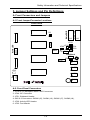
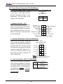
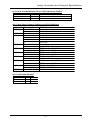
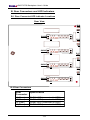
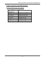
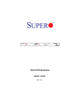
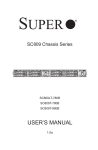
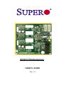
SAS733TQ Backplane
USER'S GUIDE
Rev. 1.0
SAS733TQ Backplane User’s Guide
Table of Contents
Safety Information and Technical Specifications .......................... 1-3
1. Safety Guidelines ...................................................................................... 1-3
2. Introduction to the SAS733TQ Backplane ........................................... 1-4
3. Jumper Settings and Pin Definitions ..................................................... 1-5
A. Front Connectors and Jumpers ............................................................ 1-5
A-1. Front Jumper/Connector Locations ................................................. 1-5
A-2. Front Panel Connectors .................................................................. 1-5
A-3. Front Connector Pin Definitions ...................................................... 1-6
A-4. Front Overheat/Drive Failure/Fan Failure LED Indicators .............. 1-7
A-5. Front Jumper Settings and Pin Definitions ..................................... 1-7
B. Rear Connectors and LED Indicators ................................................. 1-8
B-1. Rear Connector/LED Indicator Locations........................................ 1-8
B-2. Rear Connector/LED Indicator Descriptions ................................... 1-8
User's Guide Revision: Rev. 1.0
Release Date: 01/27/2006
1-2
Safety Information and Technical Specifications
Safety Information and Technical Specifications
1. Safety Guidelines
To avoid personal injury and property damage, please carefully
follow all the safety steps listed below when accessing your system
or handling the components:
ESD Safety Guidelines
Electric Static Discharge (ESD) can damage electronic components. To prevent damage to your system, it is important to handle it very carefully. The following measures
are generally sufficient to protect your equipment from ESD.
• Use a grounded wrist strap designed to prevent static discharge.
• Touch a grounded metal object before removing a component from the antistatic
bag.
• Handle the RAID card by its edges only; do not touch its components, peripheral
chips, memory modules or gold contacts.
• When handling chips or modules, avoid touching their pins.
• Put the card and peripherals back into their antistatic bags when not in use.
General Safety Guidelines
• Always disconnect power cables before installing or removing any components
from the computer, including the SAS733TQ Backplane.
• Disconnect the power cable before installing or removing any cable from the
SAS733TQ Backplane.
• Make sure that the SAS733TQ Backplane is securely and properly installed on
the motherboard to prevent damage to the system due to power shortage.
An Important Note to the User
• All images and layouts shown in this user's guide are based upon the latest
PCB Revision available at the time of publishing. The card you've received
may or may not look exactly the same as the graphics shown in this manual.
1-3
SAS733TQ Backplane User’s Guide
2. Introduction to the SAS733TQ Backplane
A. Overview
The SAS733TQ Backplane is a highly efficient, highly compatible and easy to use
SES-2 backplane that offers the most advanced functionality provided by the Serial
Attached/Serial Link Industry in a slim package. With the built-in AMI MG 9071 chip,
the SAS733TQ Backplane allows the user to configure RAID 0, RAID 1 and RAID 5,
maximizing data storage capability and data transferring reliability. Additionally, the
SAS733TQ supports SATA up to 3Gbps and SAS up to 3Gbps with *SES-2 (SCSI
Enclosure Services-2) capabilities, providing complete Serial Attached Services and
Serial Link Solutions to the market. (*Refer to the section below.)
B. Backplane Features
The SAS733TQ Backplane supports the following features when it is installed on a
motherboard that has an onboard SAS controller:
1.
Compatible with SATA drives
2.
Supporting SAS drives with a transfer rate of 3Gbps
3.
Supporting I2C Interface to communicate with SAS/SATA Host Bus Adaptors
(HBA)
4.
Minimizing the need for cables and connectors, uncluttering server space, and
providing a trouble-free installation environment for the user
5.
Supporting SES-2 (SCSI Enclosure Services-2) protocol, providing the following
features:
•
Drive activity and drive failure indication for each drive slot
•
Overheat/drive failure alarm via a buzzer installed on the backplane
•
An overheat/drive failure LED Indicator built in
•
Temperature Monitoring via a 2 wire (I2C) temperature sensor in the
MG 9071 chip
1-4
Safety Information and Technical Specifications
3. Jumper Settings and Pin Definitions
A. Front Connectors and Jumpers
A-1 Front Jumper/Connector Locations
+
D3
J10
JP46
JP62
JP18
JP34
JP50
JP29
I2C JP44 JP40
SideBand
JP51
JP42
JP47
SAS#3
J8
SAS#2
J7
JP61
SAS#1
J6
JP22
Fan
J13
JP33
MG
9071
JP26
Act-In LED
D4
Main PWR
Main PWR
Front View
S UPER
R
SAS#0
J5
SAS733TQ
A-2. Front Panel Connectors
1. JP10/JP13: Backplane Main PWR Connectors
2. JP44: I2C Connector
3. JP51: Sideband Header
4. SAS 0-3 Connectors: SAS#0 (J5), SAS#1 (J6), SAS#2 (J7), SAS#3 (J8),
5. JP26: Activity LED Header
6. JP22: Fan Header
1-5
SAS733TQ Backplane User’s Guide
A-3. Front Panel Connector Pin Definitions
1. Backplane Main Power Connectors (JP10, JP13) Pin Definitions
You must use the 4-pin power
Backplane Main
PWR
connectors: JP10 and JP13 to
4-pin Connector
(J10)
provide adequate power to the
Backplane. See the table on the
Pins # Definition
+12 V
1
right for pin definitions.
Ground
+5V
2&3
4
2. Sideband Header: JP51
The Sideband Header is located at
JP51 on the front panel. For SAS-II
to work properly, please connect an
8-pin Sideband cable to JP51 as
shown on the right. See the table
for pin definitions.
Backplane
SB5 2
Addressing
Reset SB4 4
1
SB6
Controller ID
3
SB2
GND
GND
SB3
6
5
SB1
SDA
Backplane ID
SB7
8
7
SB0
SCL
No Connection 10
9 No Connection
Sideband Pin Definitions (JP51)
3. Activity LED Header: JP26 Pin Definitions
The Activity LED Header, located at
JP26 on the front panel, transmits
signals to indicate the activity status
of each SAS slot. For the Activity
LED Header to work properly, please
connect a 4-pin LED cable to Pin 1
to Pin 4 of JP26 as shown on the
right. See the table in Section A-5
for pin definitions.
JP26
SAS Activity LED
Pin# Pin#
Act In#0
1
6
NC
Act In#1
2
7
NC
Act In#2
3
8
NC
Act In#3
4
9
NC
5
NC
Empty
(*Note 1: "NC"=No Connection,
Note 2: Connect a 4-pin LED cable to
Pin1-Pin 4 of JP26 only.)
4. 3-pin Fan Header: JP22 Pin Definitions
The 3-pin Fan Header is located at
JP22 on the front panel. To prevent
Overheat, please connect an 3-pin
fan cable to JP22. See the table for
pin definitions. (*Notes: 1. The Fan
Header uses DC power. 2. Default:
Fan Disabled.)
1-6
Fan Header Pin Definitions
Pin
Definition
Number
Ground (black)
1
+12V (red)
2
Tachometer
3
Caution: Fan headers are DC
power.
Safety Information and Technical Specifications
A-4 Front Overheat/Drive Failure LED Indicators: D3/D4
Front LED
State
Specification
D3 (Front)
D4 (Front)
On
On
Overheat , Drive Failure or Fan Failure
Fan Failure Only
A-5 Front Panel Jumper Settings and Pin Definitions
Jumper
Description
Definition
JP18
Open (*Default)
Short
Open (*Default)
1
2
3
4
Open (*Default)
Short
1-2
2-3 (*Default)
1-2 (*Default)
2-3
Short
Open (*Default)
1-2
2-3 (*Default)
Open
Short (*Default)
Open (*Default)
Normal
Buzzer Reset
Act #0-3 In
Act In #0
Act In #1
Act In #2
Act In #3
Normal
MG9071 Reset
2
I C Controller ID: SGPIO
2
2
I C Controller ID: I C
2
I C Backplane ID: ID#0
2
I C Backplane ID: ID#1
2
I C Reset: SGPIO
2
2
I C Reset: I C
I2C Backplane ID: SGPIO
2
2
I C Backplane ID: I C
2
I C Reset: SGPIO
2
2
I C Reset: I C (On)
SideBand Header
JP26
JP29
JP33
JP34
JP40
JP42
JP50
JP51
A-6 Fan Enable/Disable
JP61 JP62
Fan Enabled On
Pins 1-2
Fan Disabled Off Pins 2-3
1-7
SAS733TQ Backplane User’s Guide
B. Rear Connectors and LED Indicators
B-1 Rear Connector/LED Indicator Locations
Rear View
D15
D8
SAS#3
J4
D14
D7
SAS#2
J3
D13
D6
SAS#1
J2
D12
D5
SAS#0
J1
B-2 Rear Connectors
Rear
Connector
J1 (Rear)
J2 (Rear)
J3 (Rear)
J4 (Rear)
Rear LED
Indicators
D12 (Rear)
D13 (Rear)
Specification
SAS#0 HDD (connected to HDD)
SAS#1 HDD (connected to HDD)
SAS#2 HDD (connected to HDD)
SAS#3 HDD (connected to HDD)
Specification
SAS#0 Activity LED
1-8
SAS#1 Activity LED
Rear
Connector
Specification
Safety Information and Technical Specifications
J1 (Rear)
SAS#0 HDD (connected to HDD)
J2 (Rear)
SAS#1
to HDD)
B. Rear
Connectors
andHDD
LED(connected
Indicators
J3 (Rear)
SAS#2 HDD (connected to HDD)
J4 (Rear)
SAS#3 HDD (connected to HDD)
B-3 Rear LED Indicator Descriptions
Rear LED
Indicators
D12 (Rear)
D13 (Rear)
D14 (Rear)
D15 (Rear)
D5 (Rear)
D6 (Rear)
D7 (Rear)
D8 (Rear)
Specification
SAS#0 Activity LED
SAS#1 Activity LED
SAS#2 Activity LED
SAS#3 Activity LED
SAS#0 Fail LED
SAS#1 Fail LED
SAS#2 Fail LED
SAS#3 Fail LED
1-9
SAS733TQ Backplane User’s Guide
Notes
1-10