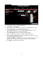
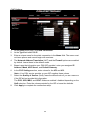
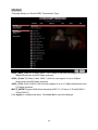
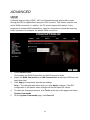
1
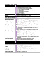
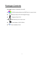
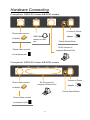
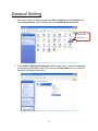
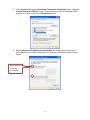
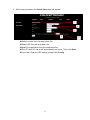
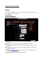
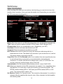
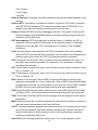
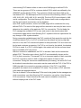
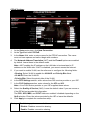
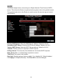
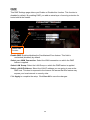
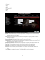
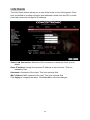
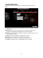
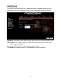
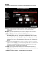
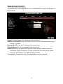
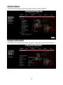
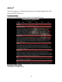
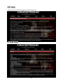
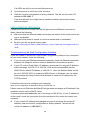
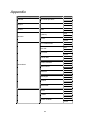
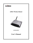
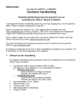
Conceptronic CADSLR4+ Annex A/B Version 4.1 July 2006 Table of Contents Specification ................................................................Error! Bookmark not defined. Package Contents ...................................................................................................... 5 Hardware Connecting................................................................................................. 6 LED Indicators ............................................................................................................ 7 General Setting........................................................................................................... 8 Advanced Setup ....................................................................................................... 12 Setup ................................................................................................................. 12 LAN Setup.................................................................................................. 12 LAN Configuration ...................................................................................... 12 Ethernet Switch .......................................................................................... 14 WAN Setup................................................................................................. 15 New Connection ......................................................................................... 15 PPPoE Settings................................................................................... 18 PPPoA Settings................................................................................... 20 Static Settings ..................................................................................... 22 DHCP Settings .................................................................................... 23 Bridge Settings.................................................................................... 24 CLIP Settings ...................................................................................... 25 Modem ....................................................................................................... 26 ADVANCED....................................................................................................... 27 UPnP.......................................................................................................... 27 SNTP.......................................................................................................... 28 Port Forwarding.......................................................................................... 29 DMZ ........................................................................................................... 30 Custom Port Forwarding ............................................................................ 31 IP Filter ....................................................................................................... 32 Custom IP Filters........................................................................................ 32 LAN Clients ................................................................................................ 34 LAN Isolation .................................................Error! Bookmark not defined. TR-068 WAN Access.....................................Error! Bookmark not defined. Bridge Filters .................................................Error! Bookmark not defined. Dynamic DNS Client................................................................................... 35 IGMP Proxy ................................................................................................ 36 Static Routing ............................................................................................. 37 Policy Routing ...............................................Error! Bookmark not defined. Ingress ..........................................................Error! Bookmark not defined. 1 Egress ...........................................................Error! Bookmark not defined. Shaper........................................................................................................ 38 Web Access Control ................................................................................... 39 Web Access Control ................................................................................... 39 SSH Access Control ................................................................................... 40 TOOLS .............................................................................................................. 41 System Commands .................................................................................... 41 Remote Log-Router.................................................................................... 42 User Management...................................................................................... 43 Update Gateway............................................Error! Bookmark not defined. Ping Test .................................................................................................... 44 Modem Test................................................................................................ 45 STATUS............................................................................................................. 46 Network Statistics ....................................................................................... 46 Connection Status ...................................................................................... 47 DHCP Clients ............................................................................................. 47 Modem Status ............................................................................................ 48 Product Information .................................................................................... 48 System Log ................................................................................................ 49 HELP ................................................................................................................. 50 Firewall Help .............................................................................................. 50 Bridge Filter Help........................................................................................ 50 LAN Clients Help ........................................................................................ 52 LAN Configuration Help.............................................................................. 52 PPP Connection Help................................................................................. 53 UPnP Help.................................................................................................. 53 IP QoS Help ............................................................................................... 54 RIP Help ..................................................................................................... 54 Troubleshooting ................................................................................................. 55 Appendix ........................................................................................................... 62 2 ADSL 2/2+ 4 Port Router Line Connection ADSL Features Full-rate adaptive modem G.lite adaptive modem WAN Mode Support LAN Mode Support Bridge Mode Support Router Mode Support Ethernet Features Certification OS System Requirement Power LED Indication PCB SIZE Software Upgrade RJ-11(2 wires), RJ-45 (4 port) DMT modulation and demodulation Tone detection for low power mode ATM SAR performed in software driver ITU 992.1 (G.dmt) Annex A, B, ITU 992.2 (G.lite) ITU 992.3 ADSL2 (G.dmt.bis) ITU 992.5 ADSL2+ ANSI T1.413 Issue 2 Maximum downstream rate of 24 Mbps (ADSL2+) Maximum upstream rate of 1 Mbps Maximum downstream rate of 1.5 Mbps Maximum upstream rate of 512 Kbps PPP over ATM (RFC 2364) PPP over Ethernet (RFC 2516) Bridged/routed Ethernet over ATM (RFC 2684/1483) Classical IP over ATM (RFC 1577) and PPP over Ethernet (RFC 2516) Ethernet to ADSL self-learning Transparent Bridging (IEEE 802.1D) Supports up to 128 MAC learning addresses IP routing-RIPv2 (backward compatible with RIPv1) Static routing DHCP (Dynamic Host Configuration Protocol) Server and Client NAPT (Network Address and Port Translation) NAT (Network Address Translation) ICMP (Internet Control Message Protocol) Simultaneous USB and Ethernet operation IGMP (Internet Group Management Protocol) Four RJ-45 connectors for 10/100 Mbps Ethernet LAN connection, DMZ function can be set up between them Complies with IEEE 802.3u specification Supports IEEE 802.3x Flow control in Full Duplex mode CE,LVD WIN 98SE ; WIN 2000;WIN ME;WIN XP PII-266 + 32M RAM External AC Power Power ON/OFF switch (option) Input: 90~120V or 200~240V, 50/60Hz Output: 12VAC/800mA Power, LAN1, LAN2, LAN3, LAN4, ADSL Link/Act 134mm×96.5mm Upgrade by Ethernet Port 3 Application Diagram ADSL Internet 4 Package Contents Conceptronic CADSLR4+ Annex A/B CD-ROM containing Manual and USB Driver for one port router Ethernet Cable (CAT5 UTP Straight-Through) Telephone Cable (RJ11) USB Cable only for one port router Power Adapter (12VAC 800mA) Quick Installation Guide 5 Hardware Connecting Conceptronic CADSLR4+ Annex A/B ADSL modem Connect to Power Phone cable connect USB Cable to Splitter Adapter connect to USB port Factory Reset Button RJ-45 connect to computer Ethernet Port Phone Cable connect to wall phone jack Conceptronic CADSLR4+ Annex A/B ADSL modem Connect to Power Phone cable connect RJ-45 connect to computer Ethernet Port Adapter to Splitter Factory Reset Button Phone Cable connect to wall phone jack 6 LED Indicators The LED Indicators are located on the front of the unit, they are green in color. The meanings are as follows: Conceptronic CADSLR4+ Annex A/B Label Meaning Status Indicates PWR Power LAN LAN On Off Flashing Off Power is on Power is off Flashes when data is being sent or received on the LAN connection. Indicates a link to your LAN or Network card is active. Indicates no link to LAN On Link USB initialize A valid ADSL connection. On USB ADSL On Link Conceptronic CADSLR4+ Annex A/B Label Meaning Status Indicates PWR Power LAN 1/ LAN 2/ LAN 3/ LAN 4 LAN Link On Off Flashing Power is on Power is off Flashes when data is being sent or received on the LAN connection. On Indicates a link to your LAN or Network card is active. Indicates no link to LAN A valid ADSL connection. ADSL Link Off Link 7 General Setting 1. Move your cursor as flowing sequence Start \ Settings \ Control Panel and click Control Panel. Then double-click on the Network Connections Double Click on this icon 2. In the LAN or High-Speed Internet window, right-click on icon corresponding to your network interface card (NIC) and select Properties.(This icon may be labeled Local Area Connection). 8 3. In the General Tab of the Local Area Connection Properties menu. Highlight Internet Protocol (TCP/IP) under “This connection uses the following items.” by click on it once. Click on the Properties button. 4. Select Obtain an IP Address automatically: by clicking once in the circle. Click OK button to confirm and save your changes, and the close the Control Panel. Select Obtain an IP address automatically 9 5. Release IP & Renew IP, then Check Default Gateway: 192.168.1.1. 6. Launch your PC web browser and enter the URL: http://192.168.1.1 7. In the User name/Password prompt, please type in Admin/Admin as default. 10 8. After Login procedure the Quick Start page will appear. - 1 2 3 4 XSelect country from the drop-down list. YSelect ISP from the drop-down list. ZSelect Encapsulation from the drop-down list. [The VPI and VCI value will automatically set up ok. Then click Next. rIf you can’t find your ISP setting, please click Config. 11 5 Advanced Setup Setup The Setup section allows you to create new connections, edit existing connections, and configure other basic settings. LAN Setup LAN Configuration The following is displayed LAN Setup. IP Address: Private IP address for connecting to a local private network (Default: 192.168.1.1). Netmask: Netmask for the local private network (Default: 255.255.255.0). Default Gateway: This field is optional. Enter in the IP address of the router on your network. Host Name: Required by some ISPs. If the ISP does not provide the Host name, please leave it blank. Domain Name: www.dynsns.org will provide you with a Domain Name. Enter this name in the “Domain Name” field. Enable DHCP Server: Enable or Disable DHCP Server. 12 Start IP: Sets the start IP address of the IP address pool. End IP: Sets the end IP address of the IP address pool. Lease time: The lease time is the amount of time of a network user will be allowed to connect with DHCP server. If all fields are 0, the allocated IP address will be effective forever. Click Apply to complete the setup. Click Save All to save the changes. 13 Ethernet Switch This Ethernet Switch Configuration page allows you to set value for data transfer; Physical Port: There are five kinds of mode for data transfer (Auto)(10/Half Duplex)(10/Full Duplex)(100/Half Duplex)(100/Full Duplex). Click Apply to complete the setup. Click Save All to save the changes. 14 WAN Setup New Connection When working with wide area connections, the first thing you must do is to have the handle of the connection. Once you have the handle for a Connection you must define the PVC and protocol settings for it. Name: Enter the name of your ISP. This information is for identification purposes only. Type: There six kinds of method (PPPoE/ PPPoA/ Static/ DHCP/ Bridge/ CLIP). Encapsulation: Select you encapsulation type. (Supplied by your ISP). Username: Enter the username provided by your ISP. Password: Enter the password provided by your ISP. Idle Timeout: Idle timeout means the router will disconnect after being idle for a preset amount of time. The default is 60 seconds. If you set the time to 0, the link will remain always connected to the ISP. Keep Alive: When the On Demand option is not enabled, this value specifies the time to wait without being connected to your provider before terminating the connection. To ensure that the link is always active, enter a 0 in this field. You can also enter any positive integer value in this field. Authentication: Set the required authentication protocol. (Auto/ CHAP/ PAP) MTU: Maximum transmit unit the DSL connection can transmit. It is a negotiated value that packets of no more than n bytes can be sent to the service provider. The PPPoE interface default MTU is 1492 (max) and PPPoA default MTU is 1500 (max). The minimum MTU value is 64. On Demand: Enables On Demand mode. The connection disconnects if no activity is detected after the specified idle timeout value. When checked, this field enables the following fields: 15 • Idle Timeout • Host Trigger • Valid Rx Default Gateway: If checked, this WAN connection acts as the default gateway to the Internet. Enforce MTU: This feature is enabled by default. It forces all TCP traffic to conform with PPP MTU by changing TCP maximum segment size to PPP MTU. If it is disabled, you may have issues accessing some Internet sites. Debug: Enables PPPoE connection debugging facilities. This option is used by ISP technical support and ODM/OEM testers to simulate packets going through the network from the WAN side. PPP Unnumbered: PPP Unnumbered is a special feature. It enables the ISP to designate a block of public IP addresses to the customer where it is statically assigned on the LAN side. PPP Unnumbered is, in essence, like a bridged connection. LAN: The LAN field is associated with the PPP Unnumbered field and is enabled when the PPP Unnumbered field is checked. You can specify the LAN group the packets need to go to when the PPP Unnumbered feature is activated. PVC: Permanent virtual circuit. This is a fixed virtual circuit between two users. It is the public data network equivalent of a leased line. No call setup or clearing procedures are needed. VPI: If instructed to change this, type in the VPI value for the initial connection (using PVC 0). Default = 0. VCI: If instructed to change this, type in the VCI value for the initial connection (using PVC 0). Default = 0. QoS: Quality of Service type. Select CBR (Continuous Bit Rate) to specify fixed (always-on) bandwidth for voice or data traffic. Select UBR (Unspecified Bit Rate) for applications that are non-time sensitive, such as e-mail. Select VBR (Variable Bit Rate) for burst traffic and bandwidth sharing with other applications. PCR: Divide the DSL line rate (bps) by 424 (the size of an ATM cell) to find the Peak Cell Rate (PCR). This is the maximum rate at which the sender can send cells. SCR: The Sustain Cell Rate (SCR) sets the average cell rate (long-term) that can be transmitted. MBS: Maximum burst size, a traffic parameter that specifies the maximum number of cells that can be transmitted at the Peak Cell Rate. CDVT: Cell delay variation tolerance, the maximum amount of cell delay variation that can be accommodated. Cell delay variation measures the random inter-arrival times of cells within an ATM connection due to cell transfer delay caused by buffering, multiplexing, and so on. Auto PVC: Auto-Sensing permanent virtual circuit. The overall operation of the 16 auto-sensing PVC feature relies on end-to-end OAM pings to defined PVCs. There are two groups of PVCs: customer default PVCs which are defined by the OEM/ISP and the backup PVCs. The customer default must have 0/35 as the first default PVC. The backup list of PVCs must be of the following VPI/VCI: 0/35, 8/35, 0/43, 0/51, 0/59, 8/43, 8/51, and 8/59. The list of PVCs are defined in XML and is configurable. The Auto-Sensing PVC feature itself is also configurable in that the auto-search mechanism can be disabled. Upon DSL synchronization, end-to-end OAM pings will be conducted for every defined PVCs. The result of the pings will be recorded in an array for later use to determine the usability of the particular PVC for connectivity. This list helps the PVC manage the available PVC for use, and needs to be synchronized with connections made without Auto-Sensing PVC. Update to this list is performed for any change in DSL synchronization. During connection establishment, the PVC module will first search through the list of defined default PVCs. If a PVC is found from the default list that is ping-able and not in use, the PVC module will update for that particular PVC as in-use from the list and continues processing. If a PVC is not found in the default, the backup PVC list is used. If no PVC is found again, the module will let the end-user know that no available VCC was found. With the connection established, the PVC is stored in flash as the connection default PVC. Therefore upon reboot, this PVC is automatically chosen as the PVC for that connection. This saved PVC in environment space of flash overrides the PVC connection saved in XML configuration space of flash for that connection. During the connection establishment processing, the saved PVC will be checked to see whether a connection can be made with the PVC. If the PVC is OAM ping-able, the connection process continues. If the PVC is not OAM ping-able, the search for an available PVC starts. The process of PVC selection is the same as described above. The list of default PVCs and backup PVCs need to be global for the management of all connections, non Auto-Sensing PVC connection, as well as, Auto-Sensing PVC connections. These lists allow the end-users to establish connectivity without keeping track of the PVC used. 17 PPPoE Settings 1. 2. 3. At the Setup main page, click New Connection. At the Type field select PPPoE. In the Name field, enter a unique name for the PPPoE connection. The name must not have spaces and cannot begin with numbers. 4. The Network Address Translation (NAT) and the Firewall options are enabled by default. Leave these in the default mode. 5. 6. 7. 8. 9. Note—NAT enables the IP address on the LAN side to be translated to IP address on the WAN side. If NAT is disabled, you cannot access the Internet. If you want to enable VLAN, use the reference to configure the following fields: • Sharing: Select VLAN to enable the VLAN ID and Priority Bits fields. • VLAN ID: Enter the VLAN ID. • Priority Bits: Select the priority bits of the VLAN. In the PPP Settings section, enter values from DSL service provider or your ISP. In the PVC Settings section, enter values for the VPI and VCI. Note—Your DSL service provider or your ISP supplies these values. Select the Quality of Service (QoS). Leave the default value if you are unsure or if the ISP did not provide this information. The PCR, SCR, MBS, and CDVT fields are enabled / disabled depending on the QoS selection. Enter the values provided by the ISP or leave the defaults. Click Apply to complete the connection setup. Sharing The following options are available: • Disable: Disables connection sharing. • Enable: Enables connection sharing. 18 • VLAN: The VLAN ID and Priority Bits fields are activated when VLAN is selected, which enable you to create VLAN. VLAN ID VLAN Identification. Multiple connections over the same PVC are Supported, which requires the WAN network to have VLAN support and for the DSLAMS and Routers on the ISP to handle VLAN Tags. Extended support is also available, which allows multiple connections to be placed over the single PVC without VLAN support (VLAN Tag of 0 is this special case). In this mode of operation, a received packet is flooded on all the connections that reside over it. Priority Bits Priority is given to a VLAN connection from 0-7. All packets sent over the VLAN connection have the Priority bits set to the configured value. 19 PPPoA Settings 1. 2. 3. At the Setup main page, click New Connection. At the Type field select PPPoA. Enter a unique name for the PPPoA connection in the Name field. The name must not have spaces and cannot begin with numbers. 4. The Network Address Translation (NAT) and the Firewall options are enabled by default. Leave these in the default mode. If you want to enable VLAN, use the reference to configure the following fields: 5. 6. 7. 8. 9. • Sharing: Select VLAN to enable the VLAN ID and Priority Bits fields. • VLAN ID: Enter the VLAN ID. • Priority Bits: Select the priority bits of the VLAN. In the PPP Settings section, select the encapsulation type (LLC or VC). Note— If you are not sure, just use the default mode. In the PVC Settings section, enter values for the VPI and VCI. Note—Your DSL service provider or your ISP supplies these values. Select the Quality of Service (QoS). Leave the default value if you are unsure or if the ISP did not provide this information. The PCR, SCR, MBS, and CDVT fields are enabled / disabled depending on the QoS selection. Enter the values provided by the ISP or leave the defaults. Click Apply to complete the connection setup. Sharing The following options are available: • Disable: Disables connection sharing. • Enable: Enables connection sharing. 20 • VLAN: The VLAN ID and Priority Bits fields are activated when VLAN is selected, which enable you to create VLAN. VLAN ID VLAN Identification. Multiple connections over the same PVC are Supported, which requires the WAN network to have VLAN support and for the DSLAMS and Routers on the ISP to handle VLAN Tags. Extended support is also available, which allows multiple connections to be placed over the single PVC without VLAN support (VLAN Tag of 0 is this special case). In this mode of operation, a received packet is flooded on all the connections that reside over it. Priority Bits Priority is given to a VLAN connection from 0-7. All packets sent over the VLAN connection have the Priority bits set to the configured value. 21 Static Settings 1. 2. 3. At the Setup main page, click New Connection. At the Type field select Static. In the Name field, enter a unique name for the Static connection. The name must not have spaces and cannot begin with numbers. 4. The Network Address Translation (NAT) and the Firewall options are enabled by default. Leave these in the default mode. 5. In the Static Settings section, select the Encapsulation Type (LLC or VC). Note— If you are not sure, just use the default mode. Based upon the information your DSL/ISP provided, enter your assigned IP Address, Subnet Mask, Default Gateway (if provided), and Domain Name 6. 7. 8. 9. Services (DNS) values (if provided). For the static configuration, you can also select a Bridged connection or a Routed connection. In the PVC Settings section, enter values for the VPI and VCI. Note—Your DSL service provider or your ISP supplies these values. Select the Quality of Service (QoS). Leave the default value if you are unsure or if the ISP did not provide this information. The PCR, SCR, MBS, and CDVT fields are enabled / disabled depending on the QoS selection. Enter the values provided by the ISP or leave the defaults. 10. Click Apply to complete the connection setup. 22 DHCP Settings 1. 2. 3. At the Setup main page, click New Connection. At the Type field select DHCP. Enter a unique name for the DHCP connection in the Name field. The name must not have spaces and cannot begin with numbers. 4. The Network Address Translation (NAT) and the Firewall options are enabled by default. Leave these in the default mode. If your DSL line is connected and your DSL/IPS provider is supporting DHCP, you 5. can click Renew and the gateway retrieves an IP Address, Subnet Mask, and Gateway Address. At any time, you can release the DHCP address by clicking 6. 7. 8. Release, and renew the DHCP address by clicking Renew. Under PVC Settings, enter values for the VPI and VCI. Note—Your DSL service provider or your ISP supplies these values. Select the Quality of Service (QoS). Leave the default value if you are unsure or if the ISP did not provide this information. The PCR, SCR, MBS, and CDVT fields are enabled / disabled depending on the QoS selection. Enter the values provided by the ISP or leave the defaults. Click Apply to complete the connection setup. 23 Bridge Settings 1. 2. 3. At the Setup main page, click New Connection. At the Type field select Bridge. Enter a unique name for the Bridged connection in the Name field. The name must not have spaces and cannot begin with numbers. 4. In the Bridge Settings section, select the Encapsulation Type (LLC or VC). Note— If you are not sure, just use the default mode. In the PVC Settings section, enter values for the VPI and VCI. Note—Your DSL service provider or your ISP supplies these values. Select the Quality of Service (QoS). Leave the default value if you are unsure or if the ISP did not provide this information. 5. 6. 7. The PCR, SCR, MBS, and CDVT fields are enabled / disabled depending on the QoS selection. Enter the values provided by the ISP or leave the defaults. Click Apply to complete the connection setup. 24 CLIP Settings 1. 2. 3. At the Setup main page, click New Connection. At the Type field select CLIP. Enter a unique name for the static connection in the Name field. The name must not have spaces and cannot begin with numbers. 4. The Network Address Translation (NAT) and the Firewall options are enabled by default. Leave these in the default mode. 5. Based upon the information your DSL/ISP provided, enter your assigned IP Address, Mask, ARP Server, and Default Gateway. In the PVC Settings section, enter values for the VPI and VCI. Note—Your DSL service provider or your ISP supplies these values. Select the Quality of Service (QoS); leave the default value if you are unsure or if the ISP did not provide this information. 6. 7. 8. The PCR, SCR, MBS, and CDVT fields are enabled / disabled depending on the QoS selection. Enter the values provided by the ISP or leave the defaults. Click Apply to complete the connection setup. 25 Modem This page allows you Select ADSL Transmission Type. ADSL_ANSI_T.1413: Full-Rate (ANSI T1.413 Issue 2) with line rate support of up to 8 Mbps downstream and 832 Kbps upstream. ADSL_G.dmt: Full-Rate (G.dmt, G992.1) with line rate support of up to 8 Mbps downstream and 832 Kbps upstream. ADSL_G.lite: G.lite (G.992.2) with line rate support of up to 1.5 Mbps downstream and 512 Kbps upstream. MULTI_MODE: Support Multi-Mode standard (ANSI T1.413 Issue 2; G.dmt(G.992.1); G.lite(G.992.2)). Click Apply to complete the setup. Click Save All to save the changes. 26 ADVANCED UPnP Universal plug and play (UPnP), NAT, and firewall traversal allow traffic to pass through the RG for applications using the UPnP protocol. This feature requires one active WAN connection. In addition, the PC should support this feature. In the presence of multiple WAN connections, select a connection on which the incoming traffic is present, for example, the default WAN connection. 1. Check Enable UPnP. This enables the WAN Connection and LAN Connection fields. 2. Select the WAN Connection and LAN Connection that will use UPnP from the drop-down lists. 3. Click Apply to temporarily activate the settings. Note— The changes take effect when you click Apply; however, if the RG configuration is not saved, these changes will be lost upon RG reboot. 4. To make the change permanent, click Tools (at the top of the page) and select System Commands. On the System Commands page, click Save All. 5. 27 SNTP The Router keeps time by connecting to a Simple Network Time Protocol (SNTP) server. This allows the Router to synchronize the system clock to the global Internet. The synchronized clock in the Router is used to record the security log and control client filtering. Primary SNTP Server: Enter the SNTP Server address. Default is 0.0.0.0. Secondary SNTP Server: Enter the SNTP Server address. Default is 0.0.0.0. Tertiary SNTP Server: Enter the SNTP Server address. Default is 0.0.0.0. Timeout: Timeout (secs) for response to SNTP request. Polling Interval: Time interval (min) between two successful SNTP requests. Retry Count: Max. no of failed sntp requests to a server. Time Zone: Time zone of the location. Day Light: Daylight savings feature enabled (1) or disabled (0). Default disabled. Click Apply to complete the setup. Click Save All to save the changes. 28 Port Forwarding The port forwarding feature allows you to direct incoming traffic to specific LAN hosts based on a protocol port number and protocol. Using the Port Forwarding page, you can provide local services (for example, web hosting) for people on the Internet or play Internet games. Port forwarding is configurable per LAN group. A database of predefined port forwarding rules allows you to apply one or more rules to one or more members of a defined LAN group. You can view the rules associated with a predefined category and add the available rules for a given category. You can also create, edit, or delete your own port forwarding rules. Click here into Custom Port Forwarding setup page Click here into DMZ setup page WAN Connection: Select the WAN connection to which port forwarding is applied. Select LAN Group: Select the LAN Group to which port forwarding is applied. LAN IP: Select the IP address to host the service. Allow Incoming Ping: Enabling incoming ping (ICMP) requests on the Port Forwarding page allows the RG to respond to a ping from the Internet. DMZ: Demilitarized zone. Custom Port Forwarding: This link takes you to the Custom Port Forwarding page. Category: Custom and user-defined categories. Available Rules: Predefined and user-defined IP filtering rules for each category. Applied Rules: Lists the IP filtering rules you elect to apply for each given category. Click Apply to complete the setup. Click Save All to save the changes. 29 DMZ This DMZ Settings page allows you Enable or Disable this function. This function is disabled by default. By enabling DMZ, you add an extra layer of security protection for hosts behind the firewall. Enable DMZ Function. Enable DMZ: Enables/disables the Demilitarized Zone feature. This field is unchecked (disabled) by default. Select your WAN Connection: Select the WAN connection on which the DMZ feature is applied. Select LAN Group: Select the LAN Group on which the DMZ feature is applied. Select a LAN IP Address: Select the LAN IP address you are going to use as the DMZ host. This host is exposed to the Internet. Be aware that this feature may expose your local network to security risks. Click Apply to complete the setup. Click Save All to save the changes. 30 Custom Port Forwarding The Custom Port Forwarding page allows you to create up to 15 custom port forwarding entries to support specific services or applications, such as concurrent NAT/NAPT operation. Connection: Select the WAN connection on which the Custom Port Forwarding rule is to be applied. Enable: The Enable button is checked by default, meaning this rule is automatically applied when you click the Apply button. Application: Name of the application for which your ports will be opened. Protocol: There are three options available: TCP, UDP, and TCP and UDP. Source IP Address: You can define the source IP address from which the incoming traffic is allowed. Enter 0.0.0.0 for all. Source Netmask: Netmask of the source IP address. Enter 255.255.255.255 for all. Destination IP Address: The LAN-side destination IP address for incoming traffic. Destination Netmask: The LAN-side destination netmask for incoming traffic. The default value of this field is 255.255.255.255. Destination Port Start: The starting port number that is made open for this application. Destination Port End: The ending port number that is made open for this application. Destination Port Map: Destination port mapped on the LAN (destination) side to which packets are forwarded. There are two types of port mapping: • One-to-one (one port mapped to one) • Multiple-to-one (multiple ports mapped to one port) Click Apply to complete the setup. Click Save All to save the changes. 31 IP Filter The IP filtering feature allows you to block specific applications/services based on the IP address of a LAN device. You can use the IP Filters page to block specific traffic (for example, block web access) or any traffic from a host on your local network. A database of predefined IP filters allows you to apply one or more filtering rules to one or more members of a defined LAN group. You can view the rules associated with a predefined filter and add the available rules for a given category. You can also create, edit, or delete your own IP filter rules. Select LAN Group: Select the LAN group to which the IP filters feature will be applied. LAN IP: Select the IP address in the given LAN group to which the IP Filters feature will be applied. Block All Traffic: When checked, complete network access is blocked for the specific IP address. Block Outgoing Ping: Blocking outgoing ping (ICMP) generated from a particular LAN IP can be used if your host has a virus that attempts a Ping-of-Death Denial of Service attack. Click Apply to complete the setup. Click Save All to save the changes. Custom IP Filters The Custom IP Filters page allows you to define up to 20 custom IP filtering entries to block specific services or applications based on: • Source/destination IP address and netmask • TCP port (ranges supported) 32 • Protocol • TCP • UDP • TCP and UDP • ICMP • Any Filter Name: Name of the IP filter rule you are creating. Enable: The Enable button is checked by default, meaning this rule is automatically applied when you click Apply. Source IP: The LAN-side source IP address assigned to outgoing traffic on which filtering is applied. Source Netmask: Netmask of the source IP on your LAN side. Destination IP: You can define the destination IP address to which your source IP will be banned access. Enter 0.0.0.0 for all. Destination Netmask: Netmask of the destination IP. Enter 255.255.255.255 for all. Port Stat: The starting port number that will be blocked for this application. Port End: The ending port number that will be blocked for this application. Protocol: There are five options available: TCP, UDP, TCP and UDP, ICMP, and Any. Click Apply to complete the setup. Click Save All to save the changes. 33 LAN Clients The LAN clients feature allows you to see all the hosts on the LAN segment. Each host is qualified to be either dynamic (host obtained a lease from this RG) or static (host has a manually-configured IP address). Select LAN Connection: Select the LAN connection to which the client is to be added. Enter IP Address: Assign the dynamic IP address to the host here. This is a mandatory field. Hostname: Hostname of the client. This is an optional field. MAC Address: MAC address of the host. This is an optional field. Click Apply to complete the setup. Click Save All to save the changes. 34 Dynamic DNS Client The Dynamic DNS Client page allows you to enable/disable the Dynamic DNS feature. Connection: This field defaults to your RG’s WAN connection over which your RG will be accessed. DDNS Server: This is where you select the server from different DDNS service providers. A charge may occur depends on the service you select. DDNS Client: Enables/disables the DDNS client feature for the WAN connection. This field is disabled by default. User Name: User name assigned by the DDNS service provider. Password: Password assigned by the DDNS service provider. Domain Name: Domain name to be registered with the DDNS server. Click Apply to complete the setup. Click Save All to save the changes. 35 IGMP Proxy The IGMP Proxy page allows you to enable multicast on available WAN and LAN connections. You can configure the WAN or LAN interface as one of the following: Upstream: The interface that IGMP requests from hosts is sent to the multicast router. Downstream: The interface data from the multicast router are sent to hosts in the multicast group database. Ignore: No IGMP request nor data multicast are forwarded. Click Apply to complete the setup. Click Save All to save the changes. 36 Static Routing The Static Routing page enables you to define routes for specific subnets on the WAN/LAN side. The RG allows you to manually program the RG's routing table. Up to 16 static routes can be added. Choose a Connection: Select the LAN group or WAN connection to which a static routing subnet is to be applied. New Destination IP: The network IP address of the subnet. (You can also enter the IP address of each individual station in the subnet). Mask: The network mask of the destination subnet. Gateway: The IP address of the next hop through which traffic will flow towards the destination subnet. Metric: Defines the number of hops the between network nodes that data packets travel. The default value is 0, which means that the subnet is directly one hop away on the local LAN network. Click Apply to complete the setup. Click Save All to save the changes. 37 Shaper The Shaper Configuration page is accessed by selecting Shaper on the Advance main page. Interface: The selections are WAN/LAN interfaces except WLAN, which does not support Shaper feature. This field needs to be selected before shaper configuration. Max Rate: This field is applicable for the HTB Queue Discipline and Low Latency Queue Discipline; both are rate-based shaping algorithms. HTB Queue Discipline: The hierarchical token bucket queue discipline is a rate-based shaping algorithm. This algorithm rate shapes the traffic of a class over a specific interface. All CoSx traffic is assigned a specific rate to which data will be shaped to. For example: If CoS1 is configured to 100Kbps then even if 300Kbps of CoS1 data is being transmitted to the interface only 100Kbps will be sent out. Low Latency Queue Discipline: This is similar to the above algorithm except that CoS1 is not rate limited. So in the example above CoS1 data is not rate limited to 100Kbps but instead all 300Kbps is transmitted. The side effect is that a miss configured stream can potentially take all bandwidth. PRIOWRR: This is a priority based weighted round robin algorithm operating on CoS2-CoS6. CoS1 queues have the highest priority and are not controlled by the WRR algorithm. Click Apply to complete the setup. Click Save All to save the changes. 38 Web Access Control The Web Access Control page allows you to access the RG remotely via the web from the WAN side. Enable: Enables/disables the remote web access feature. Choose a Connection: Select the WAN connect over which the remote web access feature is enabled. Remote Host IP: Enter the IP address of the remote host. Remote Netmask: Enter the netmask of the remote host. Redirect Port: You can enter a port number in this field that is different from the well-known IP port number 80. The port number that you enter will be viewed externally and mapped to port 80 internally in the RG. Click Apply to complete the setup. Click Save All to save the changes. 39 SSH Access Control The SSH Access Control page allows you to access the RG remotely via SSH from the WAN side. Enable: Enables/disables the remote web access feature. Choose a Connection: Select the WAN connect over which the remote web access feature is enabled. Remote Host IP: Enter the IP address of the remote host. Remote Netmask: Enter the netmask of the remote host. Click Apply to complete the setup. Click Save All to save the changes. 40 TOOLS The Tools section allows you to save the configuration, restart the gateway, update the gateway firmware, setup user and remote log information and run Ping and Modem tests. System Commands System Commands allow you to carry out basic system actions, Press the button to execute a command. 41 Remote Log-Router The Router Table page displays routing table and allows the user to manually enter the routing entry. The routing table will display the routing status of Destination, Netmask, Gateway and Interface. The interface br0 means the USB interface; Io0 means the loopback interface and ppp1 means the PPP interface. The Gateway is the learned Gateway. Click Apply to complete the setup. Click Save All to save the changes. 42 User Management User Management is used to change your User Name or Password. User Name: Default is ‘Admin’. You can enter your new user name here. Password: Default is ‘Admin’. You can enter your new password here. Confirmed Password: Enter your new password here again to confirmed. Idle Timeout: The default is 30minutes. You will need to log back onto the RG after your session has been inactive for 30 minutes. You can change the timeout here. Click Apply to complete the setup. Click Save All to save the changes. 43 Firmware Upload To update your gateway firmware, choose an update image (Kernel/ File system) or configuration file In Select a File, and then click the Update Gateway button. Additionally, you may download your configuration file from the system by clicking Get Configuration. Ping Test Packet INternet Groper is protocol that sends out ICMP echo requests to test whether or not a remote host is reachable. 44 Modem Test The Modem Test page is used to check the connectivity to the WAN. This test may take a few seconds to complete. Before running this test, make sure you have at least one WAN connection configured and have a valid DSL link. If the DSL link is not connected, the test will fail. Also make sure the DSLAM supports this feature. Not all DSLAMs have F4 and F5 support. F4/F5 cells are used for operation, administration, and maintenance (OAM) on ATM level. 45 STATUS The Status section allows you to view the Status/Statistics of different connections and interfaces. Network Statistics The Ethernet Network Statistics page shows the statistics for the Ethernet connection. The DSL Network Statistics page shows the statistics for the DSL connection. The Wireless Network Statistics page shows the statistics for the Wireless connection. 46 Connection Status The Connection Status page shows the status of PPP for each PPP interface. DHCP Clients The DHCP Clients page shows the MAC Address, IP Address, Host Name and Lease Time. 47 Modem Status The Modem Status page shows the modem status and DSL statistics. Product Information The Product Information page shows the product information and software versions. 48 System Log The System Log page shows the events triggered by the system. 49 HELP This section takes you to different Help Sections for Firewall, Bridge Filters, LAN Clients and PPP Connection. Firewall Help Help for Port Forwarding, Access Control, and Advanced Security. Bridge Filter Help Help section for Bridge Filters. 50 51 LAN Clients Help Help section for LAN Clients. LAN Configuration Help Help section for LAN Configuration. 52 PPP Connection Help Help for establishing a PPP Connection. UPnP Help Help pages for UPnP. 53 RIP Help Help section for RIP (Routing Information Protocol). IP QoS Help 54 Troubleshooting This chapter gives information about troubleshooting your ADSL Router. After each problem description, instructions are provided to help you diagnose and solve the problem. For the common problems listed, go to the section indicated. Is the router on? Have I connected the router correctly? Go to Basic Functioning. I can't access the router's configuration with my browser. Go to Troubleshooting the Web Configuration Interface. I've configured the router but I can't access the Internet. Go to Troubleshooting the ISP Connection. I can't remember the router's configuration password. I want to clear the configuration and start over again. Go to Restoring the Default Configuration and Password. Basic Functioning After you turn on power to the router, the following sequence of events should occur: 1. When power is first applied, verify that the Power LED is on. 2. Verify that other LED lights within a few seconds, indicating that the self-test procedure is running. 3. After approximately 30 seconds, verify that : a. The LAN port LEDs are lit for any local ports that are connected. b. The WAN port LED is lit. If a port's LED is lit, a link has been established to the connected device. If any of these conditions does not occur, refer to the appropriate following section. Power LED Not On If the Power and other LEDs are off when your router is turned on : Make sure that the power cord is properly connected to your router and that the power supply adapter is properly connected to a functioning power outlet. Check that you are using the 12V AC/800mA power adapter supplied by ADSL for this product. If the error persists, you have a hardware problem and should contact technical support. 55 If all LEDs are still on one minute after power up: Cycle the power to see if the router recovers. Clear the router's configuration to factory defaults. This will set the router's IP address to 192.168.1.1. If the error persists, you might have a hardware problem and should contact technical support. LAN or WAN Port LEDs Not On If either the LAN LEDs or WAN LED do not light when the Ethernet connection is made, check the following: Make sure that the Ethernet cable connections are secure at the router and at the hub or workstation. Make sure that power is turned on to the connected hub or workstation. Be sure you are using the correct cable : When connecting the router's WAN ADSL port, use the cable that was supplied with the ADSL. Troubleshooting the Web Configuration Interface If you are unable to access the router's Web Configuration interface from a computer on your local network, check the following: If you are using an Ethernet-connected computer, check the Ethernet connection between the computer and the router as described in the previous section. If your PC uses a Fixed (Static) IP address, ensure that it is using an IP Address within the range 192.168.1.2 to 192.168.1.254 and thus compatible with the ADSL Router default IP Address of 192.168.1.1. Also, the Network Mask should be set to 255.255.255.0 to match the ADSL Router. In Windows, you can check these settings by using Control Panel-Network to check the Properties for the TCP/IP protocol. Follow the instructions to configure your computer. Note: If your computer's IP address is shown as 169.254.x.x: Recent versions of Windows and MacOS will generate and assign an IP address if the computer cannot reach a DHCP server. These auto-generated addresses are in the range of 169.254.x.x. If your IP address is in this range, check the connection from the computer to the router and reboot your computer. If your router's IP address was changed and you do not know the current IP address, clear the router's configuration to factory defaults. This will set the router's IP address to 192.168.1.1. 56 Using the Reset button. Make sure your browser has Java, JavaScript, or ActiveX enabled. If you are using Internet Explorer, click Refresh to be sure the Java applet is loaded. Try quitting the browser and launching it again. Make sure you are using the correct login information. The factory default login name is Admin and the password is Admin. Make sure that CAPS LOCK is off when entering this information. If the router does not save changes you have made in the Web Configuration Interface, check the following: When entering configuration settings, be sure to click the APPLY button before moving to another menu or tab, or your changes are lost. Click the Refresh or Reload button in the Web browser. The changes may have occurred, but the Web browser may be caching the old configuration. Troubleshooting the ISP Connection If your router is unable to access the Internet, you should check the ADSL connection, then the WAN TCP/IP connection. ADSL link If your router is unable to access the Internet, you should first determine whether you have an ADSL link with the service provider. The state of this connection is indicated with the WAN LED. WAN LED On or Blinking If your WAN LED is on or blinking, then you have a good ADSL connection. You can be confident that the service provider has connected your line correctly and that your wiring is correct. WAN LED Off If your WAN LED is blinking, then your router is attempting to make an ADSL connection with the service provider. The LED should turn on within several minutes. If the WAN LED does not turn on, disconnect all telephones on the line. If this solves the problem, reconnect the telephones one at a time, being careful to use a splitter on each telephone. If the splitters are connected correctly, you should be able to connect all your telephones. If disconnecting telephones does not result in a green WAN LED, there may be a problem with your wiring. 57 If the telephone company has tested the ADSL signal at your Network Interface Device (NID), then you may have poor quality wiring in your house. If disconnecting telephones does not result in a green WAN LED the problem may be one of the following: Check that the telephone company has made the connection to your line and tested it. Verify that you are connected to the correct telephone line. If you have more than one phone line, be sure that you are connected to the line with the ADSL service. It may be necessary to use a swapper if you ADSL signal is on pins 1 and 4 or the RJ-11 jack. The ADSL Router uses pins 2 and 3. Obtaining a WAN IP Address If your router is unable to access the internet, and your WAN LED is on or blinking, you should determine whether the router is able to obtain a WAN IP address from the ISP. Unless you have been assigned a static IP address, your router must request an IP address from the ISP. You can determine whether the request was successful using the browser interface. To check the WAN IP address from the browser interface: 1. Launch your browser and select an external site such as www.yahoo.com. 2. Access the Main Menu of the router's configuration at http://192.168.1.1. 3. Under the Maintenance heading check that an IP address is shown for the WAN Port. If 0.0.0.0 is shown, your router has not obtained an IP address from your ISP. If your router is unable to obtain an IP address from the ISP, the problem may be one of the following: Your ISP may require a Multiplexing Method or Virtual Path Identifier/Virtual Channel Identifier (VPI/VCI) parameter. Verify with your ISP the Multiplexing Method and parameter value, and update the router's ADSL Settings accordingly. Your ISP may require a login program. Ask your ISP whether they require PPP over Ethernet (PPPoE) or PPP over ATM (PPPOA) login. If you have selected a login program, you may have incorrectly set the Service Name, User Name and Password. See "Troubleshooting PPPoE or PPPoA", below. Your ISP may check for your computer's host name. 58 Assign the computer Host Name of your ISP account to the router in the browser-based Setup Wizard. Your ISP only allows one Ethernet MAC address to connect to Internet, and may check for your computer's MAC address. In this case: Inform your ISP that you have bought a new network device, and ask them to use the router's MAC address. Or configure your router to spoof your computer's MAC address. This can be done in the Basic Settings menu. Troubleshooting PPPoE or PPPoA The PPPoE or PPPoA connection can be debugged as follows: 1. 2. 3. 4. Access the Main Menu of the router at http://192.168.1.1. Under the Maintenance heading, select the Router Status link. Click the Connection Status button. If all of the steps indicate "OK" then your PPPoE or PPPoA connection is up and working. 5. If any of the steps indicates "Failed", you can attempt to reconnect by clicking "Connect". The router will continue to attempt to connect indefinitely. If you cannot connect after several minutes, you may be using an incorrect Service Name, User Name or Password. There also may be a provisioning problem with your ISP. Note: Unless you connect manually, the router will not authenticate using PPPoE or PPPoA until data is transmitted to the network. Troubleshooting Internet Browsing If your router can obtain an IP address but your computer is unable to load any Web pages from the Internet: Your computer may not recognize any DNS server addresses. A DNS server is a host on the Internet that translates Internet names (such as www addresses) to numeric IP addresses. Typically your ISP will provide the addresses of one or two DNS servers for your use. If you entered a DNS address during the router's configuration, reboot your computer and verify the DNS address. Alternatively, you can configure your computer manually with DNS addresses, as explained in your operating system documentation. Your computer may not have the router configured as its TCP/IP router. If your computer obtains its information from the router by DHCP, reboot the computer 59 and verify the router address. Troubleshooting a TCP/IP Network Using the Ping Utility Most TCP/IP terminal devices and routers contain a ping utility that sends an echo request packet to the designated device. The device then responds with an echo reply. Troubleshooting a TCP/IP network is made very easy by using the ping utility in your computer. Testing the LAN Path to Your Router You can ping the router from your computer to verify that the LAN path to your router is set up correctly. To ping the router from a PC running Windows 98se or later: 1. From the Windows toolbar, click the Start button and select Run. 2. In the field provided, type Ping followed by the IP address of the router, as in this example: ping 192.168.1.1 3. Click OK. You should see a message like this one: Pinging <IP address> with 32 bytes of data If the path is working, you see this message: Reply from < IP address >: bytes=32 time=NN ms TTL=xxx If the path is not working, you see this message: Request timed out If the path is not functioning correctly, you could have one of the following problems: Wrong physical connections — Make sure the LAN port LED is on. If the LED is off, follow the instructions in "LAN or WAN Port LEDs Not On". — Check that the corresponding LEDs are on for your network interface card and for the hub ports (if any) that are connected to your workstation and router. Wrong network configuration — Verify that the Ethernet card driver software and TCP/IP software are both installed and configured on your PC or workstation. — Verify that the IP address for your router and your workstation are correct and that the addresses are on the same subnet. Testing the Path from Your Computer to a Remote Device After verifying that the LAN path works correctly, test the path from your PC to a remote device. 60 From the Windows run menu, type: ping -n 10 <IP address> where <IP address> is the IP address of a remote device such as your ISP's DNS server. If the path is functioning correctly, replies as in the previous section are displayed. If you do not receive replies: — Check that your PC has the IP address of your router listed as the default router. If the IP configuration of your PC is assigned by DHCP, this information will not be visible in your PC's Network Control Panel. Verify that the IP address of the router is listed as the default router. — Check to see that the network address of your PC (the portion of the IP address specified by the netmask) is different from the network address of the remote device. — Check that your modem is connected and functioning. — If your ISP assigned a host name to your PC, enter that host name as the Account Name in the Basic Settings menu. — Your ISP could be rejecting the Ethernet MAC addresses of all but one of your PCs. Many broadband ISPs restrict access by only allowing traffic from the MAC address of your broadband modem, but some ISPs additionally restrict access to the MAC address of a single PC connected to that modem. If this is the case, you must configure your router to "clone" or "spoof" the MAC address from the authorized PC. Restoring the Default Configuration and Password This section explains how to restore the factory default configuration settings, changing the router's administration password to password and the IP address to 192.168.1.1. You can erase the current configuration and restore factory defaults in two ways: In Tools-> System Commands -> Restore Defaults. Use the Default Reset button on the rear panel of the router. Use this method for cases when the administration password or IP address is not known. Using the Reset button To restore the factory default configuration settings without knowing the administration password or IP address, you must use the Default Reset button on the rear panel of the router. 1. Press and hold the Default Reset button until all LED turns off (about 6 seconds). 2. Release the Default Reset button and wait for the router to reboot. 61 Appendix Country Australia ISP All Internet providers PVC VPI:8 VCI:35 VPI:0 Belgium VCI:33 Canada VPI:0 Telus VCI:35 Cybercity VPI:8 VCI:35 Danmark Tiscali VPI:8 VCI:35 1 & 1 Internet DSL VPI:1 VCI:32 AOL DSL VPI:1 VCI:32 Arcor DSL VPI:8 VCI:35 Freenet DSL VPI:1 VCI:32 Fireline networks VPI:1 VCI:32 Deutschland GMX Internet VPI:1 VCI:32 Hansenet VPI:8 VCI:35 Netcologne VPI:8 VCI:35 Schlund VPI:1 VCI:35 Snafu ADSL VPI:1 VCI:32 Tiscali VPI:1 VCI:32 T-online VPI:1 VCI:32 Anderer Anbieter VPI:1 VCI:32 62 Country ISP Wannadoo France Tiscali ISRAEL KPN PPPoE LLC Telecom Italia Italian Rest oil presente KPN PPPoA VC-MuX Netherlands BBeyond Bridge LLC BBeyond PPPoA VC-MuX New Zealand New Zealand Telecom Portugal Todos os apresentador Albura Spanish Colt Teeccom Earth Eresmas Jazztel Ola Internet Retevision Terra Spanish Tiscali Telefornica Telepac Uni2 Ya.com Wanadoo 63 PVC VPI:8 VCI:35 VPI:8 VCI:35 VPI:8 VCI:48 VPI:8 VCI:35 VPI:8 VCI:35 VPI:8 VCI:48 VPI:0 VCI:33 VPI:0 VCI:35 VPI:0 VCI:100 VPI:0 VCI:35 VPI:1 VCI:32 VPI:0 VCI:35 VPI:8 VCI:32 VPI:8 VCI:35 VPI:8 VCI:35 VPI:8 VCI:35 VPI:0 VCI:35 VPI:8 VCI:32 VPI:1 VCI:32 VPI:8 VCI:32 VPI:8 VCI:35 VPI:1 VCI:33 VPI:8 VCI:32 VPI:8 VCI:32 Country ISP Island ssimi Suomi Landssimi Vortex Switserland Alle anbieter Sverige Skanova Hinet Taiwan Seednet Etisalat Classical IP Single User United Arab Emirates United Kingdom Etisalat Classical IP for Business British Telecom 64 PVC VPI:0 VCI:35 VPI:8 VCI:48 VPI:8 VCI:48 VPI:1 VCI:32 VPI:8 VCI:35 VPI:0 VCI:33 VPI:0 VCI:33 VPI:8 VCI:35 VPI:8 VCI:35 VPI:0 VCI:38