1
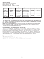
Sonata III 500 User’s Manual Manuel de l’utilisateur Anwenderhandbuch Manuale per l’operatore Manual del usuario পᡅ䂀ᯢ At Antec, we continually refine and improve our products to ensure the highest quality. As such it’s possible that your new case may differ slightly from the descriptions in this manual. This isn’t a problem; it’s simply an improvement. As of the date of publication, all features, descriptions, and illustrations in this manual are correct. Disclaimer This manual is intended only as a guide for Antec’s Computer Enclosures. For more comprehensive instructions on installing the motherboard and peripherals, please refer to the user’s manuals that come with those components. SONATA III 500 USER’S MANUAL The Sonata III 500 comes with a 500 Watt EarthWatts™ power supply unit (PSU) which is built to be compatible with the ATX12V version 2.2 specification. This PSU features higher energy efficiency which reduces power consumption by up to 25%, saving you money on your electricity bill. EarthWatts power supplies have achieved 80 PLUS® Certification, the latest independent standard in power supply efficiency. In addition EarthWatts includes a variety of protective circuitry: OPP (over power protection), OVP (Over Voltage Protection), and SCP (Short Circuit Protection). EarthWatts also includes Universal Input with Active Power Factor Correction (PFC). Universal Input allows you to connect your Antec EarthWatts power supply to any AC power outlet between 100~240V without having to worry about setting a voltage switch. Active PFC reduces electrical waste by improving the power factor value to the power supply, helping the power plant to provide power to users more efficiently. Power Switch: This power supply comes with a main power switch. Make sure you turn the switch to the ON (I) position before you boot up your computer for the first time. In normal operation there is no need to turn the switch to the OFF (O) position since the power supply is equipped with a soft on/off feature, which turns your computer on and off through the soft switch on your computer case. You may need to turn the switch to the OFF position occasionally should your computer crash and you cannot shut it down through use of the soft switch. SETTING UP Place the case upright on a flat, stable surface. The power supply fan should be at the back, facing you. Remove the thumbscrews from the panel with the latch. Unlock the side panel, swing the panel out, and remove it. Set the panel safely aside. Note: Please do not try to use your fingernails to pry or lift the panel. Inside the case you should see the power supply, a 120mm TriCool™ fan (preinstalled), some wiring with marked connectors (USB, PWR etc.), an installed I/O panel, and a power cord. You will also find a bag of hardware (screws, brass standoffs, plastic stands, etc.) 1 INSTALLING THE MOTHERBOARD This manual does not cover CPU, RAM, or expansion card installation. Please consult your motherboard manual for specific mounting instructions and troubleshooting. 1. Lay the case down, with the open side facing up. The drive cages and power supply should be visible. 2. Make sure you have the correct I/O panel for your motherboard. If the panel provided with the case isn’t suitable, please contact your motherboard manufacturer for the correct I/O panel. 3. Line up your motherboard with the standoff holes, and remember which holes are lined up. Not all motherboards will match with all the provided holes; this is normal, and won’t affect functionally. (In other words, there will likely be extra holes.) 4. Remove your motherboard by lifting it up. 5. Screw the brass standoffs into the threaded holes that line up with your motherboard. Do not over-tighten the standoffs. Some standoffs may be pre-installed for your convenience. 6. Place your motherboard on the brass standoffs. 7. Screw in your motherboard to the standoffs with the provided Philips-head screws. Your motherboard is now installed. Connecting the Power and LED If the motherboard has a 20-pin power receptacle, detach the 4-pin attachment on the 24-pin power connector, see pictures 1 and 2. Before you connect the power supply to any of the devices, please consult the appropriate user manuals for the motherboard and other peripherals. 1. Connect the 24-pin Main Power Connector and Picture 1 Picture 2 the 4-pin or 8-pin 12V connector to the motherboard as needed. If the motherboard uses a 20-pin connector, detach the 4-pin attachment on the 24-pin power connector (see pictures 1 and 2). Note: the detachable 4-pin section cannot be For 24-pin For 20-pin motherboards motherboards used in place of a 4-pin +12V connector. 2. Connect the Reset switch (labeled RESET SW) to the motherboard at the RST connector. Polarity (positive and negative) does not matter for switches. 3. The Power Switch (labeled POWER SW) connects to the PWR connector on the motherboard. 4. The Power LED (labeled POWER LED) connector is located behind the Reset connector. For LEDs, colored wires are positive (+). White or black wires are negative (–). If the LED does not light up when the system is powered on, try reversing the connection. For more info on connecting LEDs to your motherboard, see your motherboard manual. 5. The Hard Drive LED (labeled HDD LED) connects to the hard drive activity header. CONNECTING THE USB PORTS You will find a single 10-pin connector on a cable attached to the front USB ports. This is an Intel standard connector that is keyed so that it can’t be accidentally reversed when connected to a proper Intel® standard motherboard header. Connect the 10-pin connector to your motherboard headers so that the blocked pin fits over the missing header pin. 2 Motherboard Pin Layout 1 2 9 10 Pin Signal Names Pin Signal Names 1 USB Power 1 2 USB Power 2 3 Negative Signal 1 4 Negative Signal 2 5 Positive Signal 1 6 Positive Signal 2 7 Ground 1 8 Ground 2 9 Key (No Connection) 10 Empty Pin CONNECTING THE eSATA PORT This case comes with an eSATA port in the front of the case to connect to your external SATA devices. You will find a SATA connector on a cable attached to the front eSATA port. Connect it to a SATA connector on your motherboard. CONNECTING THE AUDIO PORTS (AC’ 97 and HDA) There is an Intel standard 10-pin AC’ 97 connector and an Intel 10-pin HDA (High Definition Audio) connector. You can connect either of them to your motherboard depending on the specification of the motherboard. See instruction below: Note: Please check your motherboard manual for your audio header pin layout and make sure it matches the table below. Even if your system supports both audio standards, you may only connect one connector not both. Pin Assignment for Audio Ports (HDA and AC’97) 10 6 4 2 97531 Pin Signal Names (HDA) Pin Signal Names (AC’97) 1 MIC2 L 1 MIC In 2 AGND 2 GND 3 MIC2 R 3 MIC Power 4 AVCC 4 NC 5 FRO-R 5 Line Out (R) 6 MIC2_JD 6 Line Out (R) 7 F_IO_SEN 7 NC 8 Key (no pin) 8 Key (no pin) 9 FRO-L 9 Line Out (L) 10 LINE2_JD 10 Line Out (L) INSTALLING 3.5” DEVICES There are two external 3.5” drive bays right under the 5.25” drive bays. Press the two metal tabs on the sides of the 3.5” drive tray and pull the 3.5” drive tray out of the case. 1. 2. Remove the drive bay cover from the drive bay that you intend to install the drive. Mount your floppy drive or other external device into the drive bay. Repeat the same procedure for the other drive as necessary. 3 3. 4. Slide and lock the drive tray back into the case. Find a small 4-pin power connector on the power supply and connect it to the male 4-pin connector on the device. There are 4 internal drive bays right under the external 3.5” drive bays for hard drives. Each comes with an individual drive tray which mounts through the open side panel of the case. 1. 2. 3. 4. 5. Squeeze the metal clips on each side of the tray and slide the tray out. Mount your hard drive or other internal 3.5” device into the drive tray through the bottom silicone grommets with the special screws provided. Note: DO NOT over-tighten. Over-tightening the screws will harm the vibration and noise reducing ability of the silicone grommets. Slide and lock the tray back into the case. Find a peripherial power molex connector on the power supply and connect it to the male 4-pin or SATA connector on the device. Repeat the same procedure for the other devices as necessary. Note: You can mount the drives with either the connectors facing you or away from you. If you mount them with the connectors facing away from you (into the case) you may wish to connect the data cables before sliding the drive into the locked position. Note: Mounting the drives with the connectors facing you (towards the open side of the case) may make squeezing the release clips more difficult. 5.25” DEVICE INSTALLATION There are three 5.25” drive bays. Each drive bay comes with a plastic cover with two drive rails attached behind the cover. 1. Remove the plastic drive bay cover and remove the drive rails from the cover. You may wish to open the bezel door to facilitate this. 2. Mount the drive rails onto the sides of the 5.25” device. Make sure the metal tabs are angled on the outside and facing towards the front of the device. 3. Slide the device into the drive bay until you hear a click. 4. Mount the other devices accordingly. 5. Connect a peripherial power connector from the power supply to the male connector on each of the devices. COOLING SYSTEM The Rear Exhaust TriCool™ fan The Sonata III 500 comes with one 120mm TriCool fan preinstalled in the rear. This fan has a three-speed switch that lets you choose between quiet, performance, or maximum cooling. (See specifications below.) The fan is installed so that the air is blowing out of the case. Connect a large 4-pin connector from the power supply to the male 4-pin connector on the fan. Note: The minimum voltage to start the fan is 5V. We recommend our users to set the fan speed to high if you choose to connect the fan to a fan control device or to the Fan-Only connector found on some Antec power supplies. A fan control device regulates the fan speed by varying the voltage to it. The voltage may start as low as 4.5 V to 5V. Connecting a TriCool set on Medium or Low to a fan-control device may result in the fan not being able to start. The already lowered voltage from the fan control device will be further reduced by the TriCool circuitry below 5V. 4 Specifications: Size: 120 x 120 x 25.4 mm Rated Voltage: DC 12V Operating Voltage: 10.2V ~ 13.8V Speed Input Current Air Flow Static Pressure Acoustical Noise Input Power High 2000 RPM 0.24A (Max.) 2.24 m³ / min (79 CFM) 2.54 mm-H2O (0.10 inch-H2O) 30 dBA 2.9 W Medium 1600 RPM 0.2A 1.59 m³ / min (56 CFM) 1.53 mm-H2O (0.06 inch-H2O) 28 dBA 2.4 W Low 1200 RPM 0.13A 1.1 m³ / min (39 CFM) 0.92 mm-H2O (0.04 inch-H2O) 25 dBA 1.6 W The Front 120mm Fan This case comes with one optional 120mm fan mount in the front right behind the 3.5” internal drive bays. The front fan should be installed so that the air is blowing into the case from the front. Note: We recommend AGAINST using a front fan for maximum quiet computing. If you choose to install a front fan, we recommend you use an Antec TriCool™ 120mm fan and set the speed to LOW. MAINTAINING THE WASHABLE AIR FILTER There is a washable air filter behind the front bezel. From time to time it will be necessary to wash the installed air filter as not washing it will result in higher system temperatures and possible stability problems. We recommend checking the air filter at least once a month initially. The frequency will change depending on environmental conditions and system usage, as users who run their systems 24/7 will likely have to check/wash more often than those who do not. To remove the filter: Tilt the case backwards for easier access. Squeeze the two tabs on the filter and gently pull downwards. 5 Antec, Inc. 47900 Fremont Blvd. Fremont, CA 94538 USA tel: 510-770-1200 fax: 510-770-1288 Antec Europe B.V. Stuttgartstraat 12 3047 AS Rotterdam The Netherlands tel: +31 (0) 10 462-2060 fax: +31 (0) 10 437-1752 Customer Support: US & Canada 1-800-22ANTEC [email protected] Europe +31 (0) 10 462-2060 [email protected] www.antec.com © Copyright 2007 Antec, Inc. All rights reserved. All trademarks are the property of their respective owners. Reproduction in whole or in part without written permission is prohibited. Printed in China.