1
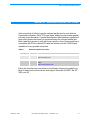
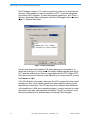
PSoC™ Designer: ICE Connection Troubleshooting User Guide Revision 2.10 (Cypress Revision **) Spec.# 38-12005 Last Revised: October 10, 2002 Cypress MicroSystems, Inc. CYPRESS MICROSYSTEMS Cypress MicroSystems, Inc. 22027 17th Avenue S.E. Suite 201 Bothell, WA 98021 Phone: 877.751.6100 Fax: 425.939.0999 http://www.cypressmicro.com/ http://www.cypress.com/aboutus/sales_locations.cfm [email protected] Copyright © 2002 Cypress MicroSystems, Inc. All rights reserved. PSoC™ (Programmable System-on-Chip) is a trademark of Cypress MicroSystems, Inc. All Gateway products referenced herein are either trademarks or registered trademarks of Gateway Inc. Products referenced on pages 11-13 are either trademarks or registered trademarks of their respective manufacturer. Sony Vaio is a registered trademark of Sony, its parent and/or its affiliates. All SIIG products referenced herein are either trademarks or registered trademarks of SIIG, Inc. All Quatech products referenced herein are either trademarks or registered trademarks of Quatech, Inc. The information contained herein is subject to change without notice. Table of Contents Section 1. Introduction ................................................................................. 1 Section 2. Connecting to the ICE ................................................................ 3 2.1 Connecting the Hardware ............................................................................................ 3 2.2 Connecting the Software ............................................................................................. 4 Section 3. Gateway BIOS Connection Issue .............................................. 7 Section 4. Sony PCG-XG29 Notebook BIOS Connection .......................... 9 Section 5. How to Access YOUR PC BIOS ............................................... 11 5.1 Changing Parallel Port Mode .....................................................................................13 Section 6. Alternate Parallel Port Cards ................................................... 15 Index ............................................................................................................ 17 October 10, 2002 Document #: 38-12005 CY Rev. ** CMS Rev. 2.10 i PSoC Designer: ICE Connection Troubleshooting Guide ii Document #: 38-12005 CY Rev. ** CMS Rev. 2.10 October 10, 2002 Section 1. Introduction Section 1. Introduction The purpose of this user guide is to facilitate establishing a connection to the In-Circuit Emulator (ICE). The PSoC ICE provides significant debugging functionality that requires full two-way communication over the ICE to operate. There are several steps in the connection process, including both setting up the hardware, and making the communications connection in the software. Making the software connection on your computer may require changes in the BIOS settings. Some recent laptops do not support EPP and Bi-directional modes in the BIOS needed for full two-way communication over the ICE. A relatively easy method that bypasses the need for changing the BIOS settings is to install a parallel port card. This has the added benefit of providing a dedicated port to the ICE without potential conflicts with other applications or printers a user may have on their computer. Section 6. Alternate Parallel Port Cards details parallel port cards for both desktops and laptops that have been tested for compliance with the ICE. We want to assist you in troubleshooting any problems with the ICE connection. If the information in this user guide is not sufficient to resolve any issues, please use the following resources: TightLink Technical Support System You can enter a support request in this system with a guaranteed responsetime of four hours: http://www.cypress.com/support/login.cfm Support Forums View and participate in discussion threads about a wide variety for PSoC MCU topics: http://forums.cypressmicro.com/ October 10, 2002 Document #: 38-12005 CY Rev. ** CMS Rev. 2.10 1 PSoC Designer: ICE Connection Troubleshooting Guide 2 Document #: 38-12005 CY Rev. ** CMS Rev. 2.10 October 10, 2002 Section 2. Connecting to the ICE Section 2. Connecting to the ICE Physically connecting your computer to the In-Circuit Emulator (ICE) and its related hardware is the first step before you can download and debug your project. The second step is connecting to the ICE inside PSoC Designer. Both steps are discussed in this section. Installing PSoC Designer on Windows NT/2000/XP requires user to have local Administrator permission. 2.1 Connecting the Hardware To physically connect your computer to the ICE (and related hardware), perform the following steps: 1. Locate the parallel interface cable, ICE, power adapter, CAT5 Patch cable, Pod, and Pup. a. Plug the parallel interface cable into the LPT1 port (back of computer). If your PC’s main connection to its printer is through LPT1, you will need to connect the ICE to an alternate port. Otherwise, this will disable other uses of the parallel port. See Alternate Parallel Port Cards page 15. b. Plug the other end of the parallel interface cable into the ICE. c. Plug the power adapter into the ICE (and AC receptor). d. Plug the CAT5 Patch cable into the ICE and the Pod. e. Connect the Pup to the Pod (if you are planning to run one of the tutorial/demonstration projects). If you are using your own circuit board, plug the Pod into your board, turn on board power, then connect the Pod to the ICE via the CAT5 cable. The ICE will automatically determine the power source. October 10, 2002 Document #: 38-12005 CY Rev. ** CMS Rev. 2.10 3 PSoC Designer: ICE Connection Troubleshooting Guide 2. Reboot your machine and launch BIOS during boot up by pressing [F2] or [Delete]. If [F2] or [Delete] do not launch your BIOS, see How to Access YOUR PC BIOS page 11 to identify the BIOS for your particular PC. 3. In BIOS Setup, select EPP mode, as this setting works most often (for both desktops and laptops). Because the BIOS settings vary per machine, the correct mode cannot be known in advance and may take some trial and error. Options include EPP, ECP, EPP+ECP, and Bi-directional. 4. Save the settings, exit the BIOS, reboot, and launch PSoC Designer. 2.2 Connecting the Software Once you have made the physical connection, you are ready to make the internal connection from PSoC Designer to the ICE. The ICE enables communication and debugging between PSoC Designer and the Pod/MCU. To connect to the ICE from inside PSoC Designer, execute the following steps (it is assumed you have already completed the following steps 1 through 3): 1. Confirm that the Pod is connected to the ICE with the CAT5 Patch cable (< 1 ft. in length). 2. Confirm that the parallel port connection is secure from the ICE to the PC. 3. Confirm that the ICE is powered from the adaptor (yellow LED on, green LED off). 4. Access the Debugger subsystem (using example project, Example_PWM_28-pin, from the ...\Examples directory of PSoC Designer). 5. Click the Connect icon . Upon successful connection, you will receive notification in the Output tab of the status window and a green indicator displaying Connected will appear in the lower-right corner of the subsystem. If you receive notification that the ICE did not connect several possibilities can be the cause: 4 Document #: 38-12005 CY Rev. ** CMS Rev. 2.10 October 10, 2002 Section 2. Connecting to the ICE 1. It has been documented that some computers running Windows 2000 can be put into the correct mode, but even when machines are rebooted once, twice, or several times, the ICE will still not connect the first time PSoC Designer launched. If this scenario is familiar, do not modify the mode (EPP, ECP, or Bi-directional) because this could be correct. Simply reboot, launch PSoC Designer, and try connecting. 2. When using Windows NT, 2000, or XP with versions of PSoC Designer 2.16 or earlier, the machine needs to be rebooted twice in order for the parallel port driver to initiate the connection for the first time. For all later versions of PSoC Designer, the machine only needs to be re-booted when the installation requests a reboot with the selection of the BIOS parallel port. 3. The correct mode has not been selected from the BIOS for the system, in which case the machine will need to be rebooted and another mode tried. Try Bi-directional, EPP+ECP, then ECP (usually for Windows 98 systems). 4. Other hardware/applications may be accessing the parallel port. For instance, printers or a full version of Adobe Acrobat can interfere with the use of the parallel port. You can redirect prints to a file. Another way to circumvent other applications interfering with the accessibility of the port is to obtain a PCI parallel card to provide a dedicated parallel port. For further details, see Alternate Parallel Port Cards page 15. If you are not interested in a dedicated port, verify that no other hardware, such as a printer or scanner, is configured to access the same LPT port as the ICE. 5. There can be issues connecting the In-Circuit Emulator (ICE) to a Gateway® Solo 9500. This problem can be solved if you upgrade the Gateway Solo 9500 BIOS, as described ahead under Gateway BIOS Connection Issue page 7. 6. Failed Hardware: Although all hardware is tested by Cypress MicroSystems before leaving the factory, it is possible to have a faulty parallel cable, CAT5 cable, or Pod. Try swapping parallel cables or Pods if possible. Swapping the CAT5 cable is not advised. (The ICE requires CAT5 cables 1 foot or less in length with all 8 wires connected. Some patch cables contain only 4 wires.) October 10, 2002 Document #: 38-12005 CY Rev. ** CMS Rev. 2.10 5 PSoC Designer: ICE Connection Troubleshooting Guide 7. The PSoC Designer error message says, "Cannot Read Pod Silicon ID. Connection may have failed. Try Again.” PSoC Designer has failed to establish communication with the pod but has established communication with the ICE base unit. Possible causes of communication failure are: Table 1: Possible Causes, “Cannot Read Pod Silicon ID...” Problem Solution The pod is not connected to the ICE. Connect the pod to the ICE. The cable connecting the pod to the ICE is seated loosely at either the end of the pod or ICE. Disconnect and reconnect the cable. A device programming board is connected to the ICE instead of the pod. Disconnect the device programming board and connect the pod. An obsolete pod is connected to the ICE (Rev. B or earlier). Upgrade to a current revision pod (Rev. G or higher as of September 2002). The pod is defective. Replace the pod. The cable is defective. Replace the CAT5 cable. Note that replacements should be obtained from CMS, and must have 8 connectors and be no more than 1 foot in length. The ICE base unit is defective. Replace the ICE base unit. If you have a device programming board, using it to program parts can test the cable and ICE base unit. If parts can be programmed, the cable and ICE base unit are good. If you have exhausted all the recommended options for connecting to the ICE please consider the following: 6 Try making the connection on an alternative PC (to rule out faulty ICE and related hardware) Contact the Cypress MicroSystems Applications Engineering Hotline at 425.939.1014 or email at [email protected] Contact your PC hardware vendor/manufacturer Document #: 38-12005 CY Rev. ** CMS Rev. 2.10 October 10, 2002 Section 3. Gateway BIOS Connection Issue Section 3. Gateway BIOS Connection Issue There can be issues connecting the In-Circuit Emulator (ICE) to a Gateway Solo 9500. This problem can be solved if you upgrade the Gateway Solo 9500 BIOS, as described ahead. Following is an excerpt from Gateway documentation found at http://www.gateway.com: Available on the Web at www.gateway.com/support are the following: technical support for Gateway products, live chat with a Gateway Trusted Guide, files for downloading, and e-mail support. Additional technical support can be obtained using our Fax on Demand system at (800) 846-4526 and our Automated Troubleshooting System at (800) 846-2118. File Description: Solo 9500 Bios Revision: 23.05.11 Operating System: NA Driver Part Number: 7510769 Date: 01/15/2002 Table of Contents Overview Identification Installation Reason for Update Applicable Part Numbers Overview This is BIOS 23.05.11 for the Solo 9500. Identification October 10, 2002 Document #: 38-12005 CY Rev. ** CMS Rev. 2.10 7 PSoC Designer: ICE Connection Troubleshooting Guide If you have a Solo 9500, you need to upgrade to this BIOS. Installation Locate the folder on your hard drive where you downloaded the driver file and double-click it. This extracts the files to your hard drive. The default location is C:\DRIVERS\7510769. Copy the extracted files to a blank floppy disk. Insert the disk into the floppy disk drive and turn on the computer. At the Gateway boot screen, press the ESC key. You are prompted to choose your boot device. Using the arrow keys, select Removable Devices, and then press the ENTER key. At the A:\ prompt, type: 230511. Press ENTER to begin the flash. When the flash is complete, the computer restarts. Remove the floppy disk from the drive. Reason for Update The BIOS was revised to: Add compatibility for additional parallel port devices. Resolve compatibility issues for Intel LanDesk Client Manager in Windows 98SE. Add MS-DOS mode compatibility for 3Com 3C575 cardbus PC card. Add support for 3Com PCI network card in the Mini-Dock in Windows NT 4.0. Applicable Part Numbers The part number for this file is 7510769. 8 Document #: 38-12005 CY Rev. ** CMS Rev. 2.10 October 10, 2002 Section 4. Sony PCG-XG29 Notebook BIOS Connection Section 4. Sony PCG-XG29 Notebook BIOS Connection The Sony Vaio® PCG-XG29 shipped without a method to alter the parallel port from ECP to EPP in the BIOS. The parallel port on this class of notebooks must be altered to work with the Cypress MicroSystems ICE and programming contest “Prongle.” Following is a free third-party software tool from Micro-Solutions that can change your parallel port from ECP to EPP mode. At http://www.micro-solutions.com/, click Downloads to access testport.exe. 1. Save in C:\windows. 2. To use: Go to full-screen DOS Prompt. 3. Type "micro-testport -epp". Hit [Enter]. 4. Type “exit" and [Enter] to go back to Windows. 5. Your parallel port should now be operational. For more information about the tool you can also type "micro-testport /?" and hit [Enter] to change to back to ECP, Uni-directional, or Bi-directional modes. Note that this utility program only works on Windows 95, 98, and possibly Me. The utility does direct writes to the parallel port. Those “writes” are not supported in Windows NT, 2000, and XP. Please note that we do not support this utility and are not responsible for failures. October 10, 2002 Document #: 38-12005 CY Rev. ** CMS Rev. 2.10 9 PSoC Designer: ICE Connection Troubleshooting Guide 10 Document #: 38-12005 CY Rev. ** CMS Rev. 2.10 October 10, 2002 Section 5. How to Access YOUR PC BIOS Section 5. How to Access YOUR PC BIOS The instructions listed below may vary depending on the manufacturer of your PC. It is recommended that you reference the documentation provided with your PC to access and change the parallel port settings. If you have questions, please contact your computer manufacturer. Many computers display BIOS access instructions while the computer boots. Pressing a key or a combination of keys before the Operating System begins to load will access the BIOS. Some common keys are [Esc], [F1], [F2], [F10], [Ctrl-Delete] or [Delete]. For more information, check the documentation that came with your computer to find out how to gain access to the computer BIOS. Table 2: BIOS Manufacturer BIOS Manufacturer Key Command(s) ALR Advanced Logic Research, Inc. ® PC / PCI [F2] ALR PC non / PCI [Ctrl+Alt+Esc] AMD® (Advanced Micro Devices, Inc.) BIOS [F1] AMI (American Megatrends, Inc.) BIOS [Delete] Award™ BIOS [Ctrl+Alt+Esc] Award BIOS [Delete] DTK® (Datatech Enterprises Co.) BIOS [Esc] Phoenix™ BIOS [Ctrl+Alt+Esc] Phoenix BIOS [Ctrl+Alt+S] Phoenix BIOS [Ctrl+Alt+Insert] This information was compiled from several sources including: http://www.iomega.com/ and http://www.hp.com October 10, 2002 Document #: 38-12005 CY Rev. ** CMS Rev. 2.10 11 PSoC Designer: ICE Connection Troubleshooting Guide Table 3: Computer Computer 12 Key Command(s) Acer® [F1], [F2], [Ctrl+Alt+Esc] AST® [Ctrl+Alt+Esc], [Ctrl+Alt+Delete] Compaq® 8700 [F10] CompUSA® [Delete] Cybermax® [Esc] Dell® 400 [F3] Dell 400 [F1] Dell Dimension® [F2] or [Delete] Dell Inspiron® [F2] Dell Latitude [Fn+F1] (while booted) Dell Latitude [F2] (on boot) Dell Optiplex [Delete] Dell Optiplex [F2] Dell Precision™ [F2] eMachine™ [Delete] Gateway® 2000 1440 [F1] Gateway 2000 Solo™ [F2] HP® (Hewlett-Packard) [F1], [F2] IBM® [F1] IBM E-pro Laptop [F2] IBM PS/2® [Ctrl+Alt+Insert] after [Ctrl+Alt+Delete] IBM Thinkpad® (newer) Windows: Programs-Thinkpad CFG Intel® Tangent [Delete] Micron™ [F1], [F2], or [Delete] Packard Bell® [F1], [F2], [Delete] Sony® VIAO [F2] Sony VIAO [F3] Tiger [Delete] Document #: 38-12005 CY Rev. ** CMS Rev. 2.10 October 10, 2002 Section 5. How to Access YOUR PC BIOS Table 3: Computer, continued Computer Key Command(s) Toshiba® 335 CDS [Esc] Toshiba Protege [Esc] Toshiba Satellite 205 CDS [F1] Toshiba Tecra [F1] or [Esc] This information was compiled from several sources including: http://www.iomega.com/ and http://www.hp.com Caution: Incorrect BIOS settings can prevent PCs from working. It is recommended that you track changes made to the BIOS in case you need to restore a previous setting. 5.1 Changing Parallel Port Mode 1. Locate the parallel port mode setting in your computer Setup. The parallel port mode settings may be located in the Advanced Settings section, Peripherals, Communication or Input/Output sections. 2. Parallel port modes set to Normal or Uni-directional will not work. Change the setting to a different mode. 3. Exit computer setup making sure you save the changes. Compaq computers with Compaq BIOS (setup) will not allow you to change the parallel port settings. You must disable the DMA channel, which will cause the parallel port to change to EPP mode. Turn off the DMA channel assigned to the port and use the same hardware configuration that the current port is assigned. This will change the mode from ECP to EPP. Example: Change 0378-037F, IRQ 7 DMA2 to: 0378-037F, IRQ7. On some older Compaq computers it may not be possible to assign the parallel port settings without a DMA setting. If this is the case, contact Compaq for a possible BIOS upgrade. October 10, 2002 Document #: 38-12005 CY Rev. ** CMS Rev. 2.10 13 PSoC Designer: ICE Connection Troubleshooting Guide 14 Document #: 38-12005 CY Rev. ** CMS Rev. 2.10 October 10, 2002 Section 6. Alternate Parallel Port Cards Section 6. Alternate Parallel Port Cards In the event that all efforts to get the onboard parallel port to work with the Cypress MicroSystems PSoC ICE have failed, adding an after market parallel port may be an alternative. Cypress MicroSystems has tested two parallel port cards with systems that have not connected using the onboard parallel port. Both cards have proven to work with these systems. One of these solutions is compatible with PCI-bus based PCs and the second uses the PCMCIA port available on many portable computers. Table 4: PC Type Alternate Parallel Port Cards Port Parallel Port Option Desktop PCI SIIG, Inc.® Cyberparallel PCI Model IO1839, Part# JJ-P00112 http://www.siig.com Portable PCMCIA Quatech, SPP-100 Enhanced Parallel Port Type II PCMCIA Card http://www.quatech.com Follow the manufacturer instructions to install and configure the parallel port. Both of these cards include drivers that support Windows 98, 98SE, Me, NT, 2000, and XP. October 10, 2002 Document #: 38-12005 CY Rev. ** CMS Rev. 2.10 15 PSoC Designer: ICE Connection Troubleshooting Guide PSoC Designer version 2.16 or later is required to make use of a second parallel port. If the parallel port card is installed as LPT2, it must be designated from within PSoC Designer. To select an alternate parallel port, click Tools >> Options. Inside the Options dialog box, select the “Debugger” tab as shown in Figure 1: Options Dialog Box: Figure 1: Options Dialog Box Use the drop-down menu labeled “ICE board debug port connected to” to select the correct port. In most cases, the default onboard parallel port will be LPT1 and the additional port that you just installed will be LPT2. Select LPT2. After the correct port is selected, press OK and try to connect the ICE in using the Connect icon . If the ICE still does not connect, make sure the ICE is connected to the correct parallel port. Also, verify that the parallel port was installed correctly per the manufacturer instructions. The PC may need to be restarted after installation of the parallel port. With some operating systems, it may be required to restart the system twice after new hardware is installed. If the PC is restarted, verify the correct parallel port is selected when re-entering PSoC Designer. 16 Document #: 38-12005 CY Rev. ** CMS Rev. 2.10 October 10, 2002 Index A Alternate Parallel Port Cards 15 B BIOS Manufacturers 11 C Changing Parallel Port Mode 13 Computer 12 Connecting the Hardware 3 Connecting the Software 4 Connecting to the ICE 3 G Gateway BIOS Connection Issue 7 H How to Access YOUR PC BIOS 11 I Introduction 1 S Sony PCG-XG29 Notebook BIOS Connection 9 Support Contacts 6 No ICE Connection 4 Support Forums 1 TightLink Technical Support System 1 October 10, 2002 Document #: 38-12005 CY Rev. ** CMS Rev. 2.10 17 PSoC Designer: ICE Connection Troubleshooting Guide Document Revision History Document Title: PSoC Designer: ICE Connection Troubleshooting Guide Document Number: 38-12005 Revision ** ECN # 115171 Issue Date 4/23/2002 Origin of Change Submit to CY Document Control. Description of Change New document to CY Document Control (Revision **). Revision 2.10 for CMS customers. Distribution: External/Public Posting: None 18 Document #: 38-12005 CY Rev. ** CMS Rev. 2.10 October 10, 2002