1
4$ (OHFWURQLFV(QJLQHHULQJIRUWKH3HRSOH 352-(&7:5$383 ',<&RORU,GHQWLILHU ,16,*K7/LQX[6RIWZDUH'HYHORSPHQW7RROV
/2&$7,21$XVWUDOLD
/2&$7,218QLWHG6WDWHV /2&$7,218QLWHG6WDWHV
3$*(
3$*(
3$*(
7K(:25/'¶66285&(I 25(0%(''('(/(&7521,&6(1*,1((5,1*,1I 250$7,21
$35,/
,668(
(0%(''('352*5$00,1*
%XLOGD&DSDFLWLYH7RXFK
3HUVRQDO$PS
$Q0&8IRU/RZ3RZHU
$SSOLFDWLRQV
0HVK1HWZRUNLQJZLWK
WKH61$326
$Q([DPLQDWLRQRI
3DUDOOHO&DSDFLWRUV
6LJPD'HOWD0RGLILHUV
([SODLQHG
3/86
6RIWZDUH6LPSOLILHG
86&DQDGD
ZZZFLUFXLWFHOODUFRP
$XWRPDWLRQ5HGXFHV5HSHWLWLYH7DVNV
$XWRPDWLF&RGH*HQHUDWRUV
&RQILJXUDWLRQ&RQWURO3URJUDPV
7HVWLQJ9HULILFDWLRQ9DOLGDWLRQ
$QG0RUH
F
ROM THE BENCH
Reprinted by permission. For subscription information, call 1.800.269.6301, or visit
www.circuitcellar.com/subscriptions. Entire contents copyright ©2012 Circuit Cellar
Inc. All rights reserved.
by Jeff Bachiochi (USA)
SNAP to It (Part 1)
Mesh Networking Simplified
Mesh networking relies on nodes to capture, distribute, and reproduce data. It is
the glue that keeps the Internet and cellular towers connected. While there are
many standard protocols available for localized networks (e.g., Wi-Fi, Bluetooth,
or wireless USB), this article focuses on the SNAP network operating system
created by Synapse Wireless.
April 2012 – Issue 261
T
68
he telephone has all but eliminated letter
writing, the long-time de facto standard
for keeping in touch with friends and families.
Today, not only has this convenience gone wireless, but it is being used for far more than staying in contact with one another. Parents arm
their kids with cell phones for peace of mind.
Kids have a texting agility that is inherited
from their video gaming skills. It’s a sad commentary that there are far fewer “minutes”
devoted to cell conversations than the senseless
plethora of audio and video candy available.
When our Boy scout troop goes camping, we
encourage the boys to leave all of their electronics at home. When traveling any distance, we
use walkie-talkies for communication between
vehicles, even though the adults have cell
phones. The boys share a responsibility to keep
tabs on every vehicle in the group and make
sure no one takes an unexpected turn. (It
amazes me how each GPS will calculate certain
routes differently.) This convoy-style string can
sometimes exceed the distance of a walkietalkie, making the middle vehicles the only
link between the front runner and the rear
sweeper. Communication must be relayed
(repeated) by one radio that has contact with
those ahead and behind. The number of repeats
or hops is related to how much the vehicles are
spread out and the range of the radios.
So it is with low-power communications.
Since transmission distance is a function of
power output, low-power radios have a rather
limited range. This can be a good thing if you
wish to limit the interference you cause. It can
be a bad thing if you need to span a considerable distance within a group of radios. When a
radio must not only transmit and receive its
own data, but also relay the data of others, it is
being used as part of a mesh network. As one
may expect, the strategies for this may be as
simple as every radio repeating what it has
heard, or as sophisticated as dynamic mapping
of the most efficient route. The simplest strategies can create a throughput clogging uproar of
activity as each receives and retransmits the
same message. So, at least a little bit of smarts
are required to cut this to an acceptable level.
MESH NETWORKS
You can think of the Internet as the world’s
largest wired mesh network. Information travels from one router (repeater/director) to the
next until it reaches its destination. Your IP
a)
b)
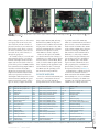
Photo 1—SNAP engine modules are available with an
integrated antenna (a) and an RP-SMA connector for
using an external antenna (b)
CIRCUIT CELLAR®
•
www.circuitcellar.com
b)
a)
c)
Photo 2—SNAP evaluation boards that accept all SNAP engine modules include the USB bridge module (a), the Prototype1 PCB (b), and
the Prototype 2 PCB (c).
ID
ID
ID
ID
ID
ID
ID
ID
ID
ID
ID
ID
ID
ID
ID
ID
ID
ID
0
1
2
3
4
5
6
7
8
9
10
11
12
13
14
15
16
17
Reserved for Synapse use
Reserved for Synapse use
MAC Address
Network ID
Channel
Multicast processed groups
Multicast forwarded groups
Manufacturing date
Device name
Last system error
Device type
Feature bits
Default UART
Buffering timeout
Buffering threshold
Intercharacter timeout
Carrier sense
Collision detect
(ZC), a ZigBee Router (ZR), and a ZigBee End Device (ZED). A single ZC
originates and coordinates the network
keeping track of all active nodes. ZRs
can pass communication as a repeater
and act as an endpoint for service,
while ZEDs are strictly endpoints.
There are other protocols available
you should consider when looking for
something to use with your new widget.
You may want to consider Wi-Fi, Bluetooth, or wireless USB as capable candidates depending on the application. Or,
read on further as I take you through
the SNAP network operating system
(OS) created by Synapse Wireless.
SYNAPSE WIRELESS
Not to be confused with USNAP (see
my article, “Smart Network Access
Point,” Circuit Cellar 246, 2011),
Synapse Wireless has created a family
ID 18
ID 19
ID 20
ID 21
ID 22
ID 23
ID 24
ID 25
ID 26
ID 27
ID 28
ID 29
ID 30
ID 31
ID 32
ID 33
ID 34–38
ID 39
Collision avoidance
Radio unicast retries
Mesh routing maximum timeout
Mesh routing minimum timeout
Mesh routing new timeout
Mesh routing used timeout
Mesh routing delete timeout
Mesh routing RREQ retries
Mesh routing RREQ wait time
Mesh routing initial hop limit
Mesh routing maximum hop limit
Mesh sequence number
Mesh override
Mesh routing LQ threshold
Mesh rejection LQ threshold
Noise floor
Reserved for future use
Radio LQ threshold
of products around the SNAP OS,
which is a communication and control
protocol used to create and maintain a
mesh network of SNAP nodes. SNAP
nodes contain a SNAP device (a microcontroller executing the SNAP OS)
that interfaces with communication
hardware (i.e., radio, I/O). A SNAP
device can be integrated directly into
your product, but is also available as
part of a SNAP engine. The SNAP
engine contains a SNAP device and
radio prepackaged as a standard footprint module, providing a common
development interface (see Photo 1).
A SNAP bridge is a SNAP node used
to connect two networks such as a
SNAP network and the Internet (SNAP
Connect E10), a PC, or a second SNAP
network. For instance, the SNAP Connect E10 is an end product incorporating
a SNAP node as a bridge between a
ID 40
ID 41
ID 42–49
ID 50
ID 51
ID 52
ID 53
ID 54–59
ID 60
ID 61
ID 62
ID 63
ID 64
ID 65
ID 66–127
ID 70
ID 128–254
ID 255
SNAPPy CRC
Platform
Reserved for future use
Enable encryption
Encryption key
Lockdown
Maximum loyalty
Reserved for future use
Last version booted (deprecated)
Reboots remaining
Reserved for future use
Alternate radio trim value
Vendor-specific settings
Clock regulator
Reserved for future use
Transmit power limit
Available for user definition
Reserved for Synapse use
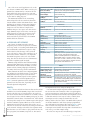
Table 1—Nonvolatile memory is set aside for internal parameters that support function configuration. Additional slots are reserved for the user.
www.circuitcellar.com
•
CIRCUIT CELLAR®
April 2012 – Issue 261
address changes when you disconnect
your laptop and reconnect at some
other location. (The IP is fixed to a
physical connection.) To remain integrated in the mesh, when you move,
you must reestablish your new location with others, either directly or
through the grapevine.
On a smaller scale, if you work with
microcontroller devices, you may be
familiar with ZigBee mesh networks.
ZigBee was conceived as the first lowpower ad-hoc protocol in 2003, with the
latest incarnation being ZigBee PRO. It
should be noted that the ZigBee
Alliance has recognized the need for
simpler networks that remain within
earshot (no repeaters) and has introduced ZigBee Radio Frequency for Consumer Electronics (RF4CE). A typical
ZigBee network may consist of three
types of devices, a ZigBee Controller
69
Datamode.py
from synapse.switchboard import *
THE NE
NEW
WP
PICOSCOPE
ICOSCOPE
2205 MSO
MSO
MIXED
MIXED SSIGNAL
IGNAL OSCILLOSCOPE
OSCILLOSCOPE
GREAT
GREAT VALUE,
VALUE, PORTABLE,
PORTABLE, H
HIGH
IGH
END
ASS SSTANDARD
END FFEATURES
EATURES A
TANDARD
AND EASY
EASY TO
TO USE
USE
otherNodeAddr = “\x00\x00\xFF” # <= put the address of the OTHER node here
@setHook(HOOK_STARTUP)
def startupEvent():
initUart(1, 9600) # <= put your desired baudrate here!
flowControl(1, False) # <= set flow control to True or False as needed
crossConnect(DS_UART1, DS_TRANSPARENT)
ucastSerial(otherNodeAddr)
Figure 1—This simple script can be loaded into two nodes enabling them to act as a wireless
serial link between two RS-232 devices.
ADC
Think
Think Logically...
Logically...
Channels
Channels
Resolution
Resolution
Bandwidth
Bandwidth
Digital
Digital frequency
frequency
Sampling
Sampling rate
rate
Trigger modes
modes
Trigger
April 2012 – Issue 261
Price
Price
70
2 An
Analog,
alog, 1
16
6 Di
Digital
gital
8 bit
Analog
Analog 25 MHz,
MHz,
Digital
Digital 100MHz
100MHz combined
combined
200MS/s
200MS/s
Window, Pulse
Pulse width,
width,
Edge, Window,
Edge,
Window pulse
pulse width,
width, Dropout,
Dropout,
Window
Window dropout,
dropout, Interval,
Interval,
Window
Runt pulse,
pulse, Di
gital, LLogic
ogic
Runt
Digital,
$575
www.picotech.com/pco467
www.picotech.com/pco467
1-800-591-2796
readAdc(channel)
Sample ADC on specified input channel, returns raw reading
cbusRd(numToRead)
cbusWr(byteStr)
CBUS Master Emulation
Reads numToRead bytes from CBUS, returns string
Writes every byte in byteStr to the CBUS
setPinDir(pin, isOutput)
setPinPullup(pin, isEnabled)
setPinSlew(pin, isRateCon-
GPIO
Set direction for parallel I/O pin
Enable pull-up resistor for Input pin
Enable slew rate control for Output pin
monitorPin(pin, isMonitored)
pulsePin(pin, msWidth,
isPositive)
Enable GPIN events on Input pin
Apply pulse to Output pin
readPin(pin)
writePin(pin, isHigh)
setRate(rateCode)
Read current level of pin
Set Output pin level
Set pin sampling rate to off (0), 100 ms (1), 10 ms (2), or
1 ms (3)
i2cWrite(str, retries, ignoreFirstAck)
I2C Master Emulation
Returns the result of the most recent I2C operation
Prepare for I2C operations
Write str out, then read numBytes back in from I2C bus.
Parameters retries and ignoreFirstAck are used with slow
or special case devices
Write str out over the I2C bus. Parameters retries and
ignoreFirstAck are used with slow or special case devices
setSegments(segments)
bist()
eraseImage()
resetVm()
Miscellaneous
Set eval board LED segments (clockwise bitmask)
Built-in self test
Erase user-application flash memory
Reset the embedded virtual machine (prep for upload)
initVm()
vmStat(statusCode, args...)
writeChunk(ofs, str)
chr(number)
Initialize embedded virtual machine
Solicit a tellVmStat for system parameters
Write string to user-application flash memory
Returns the character string representation of “number”
str(obj)
int(obj)
Returns the string representation of obj
Returns the integer representation of obj. Notice that you
cannot specify the base. Decimal is assumed.
len(str)
random()
stdinMode(mode, echo)
Returns the length of string str (0–255)
Returns a pseudo-random number 0–4,095
Mode is 0 for line, 1 for character at a time
getI2cResult()
i2cInit(enablePullups)
i2cRead(str, numBytes,
retries, ignoreFirstAck)
Table 2 continued on p. 71
Table 2—The built-in SNAPPy API functions available grouped together by the category.
CIRCUIT CELLAR®
•
www.circuitcellar.com
Network
Current network ID
Set network ID (1–0xFFFE)
Local network address (3-byte binary string)
Originating address of current RPC context (none if
called outside RPC)
getNetId()
setNetId(netId)
localAddr()
rpcSourceAddr()
mcastSerial(dstGroups, ttl)
ucastSerial(dstAddr)
callback(callbackFnObj,
remoteFnObj, args...)
callout(addr, callbackFnObj,
remoteFnObj, args...)
rpc(dstAddr, remoteFnObj, args...)
Set serial transparent mode to multicast
Set serial transparent mode to unicast
RPC (back to the original invoker) of RPC results
mcastRpc(dstGroups, ttl,
remoteFnObj, args...)
RPC (multicast)
loadNvParam(id)
saveNvParam(id, obj)
RPC (unicast)
Nonvolatile (NV) Parameters
Load indexed parameter from NV storage
Save object to indexed NV storage location
Radio
Enable/disable radio receiver
Adjust radio transmit level (0 is lowest, 17 is highest)
Set radio channel
Radio channel
Link quality in (–) dBm
Detected RF energy in (–) dBm (current channel)
Detected RF energy in (–) dBm (all 16 channels)
Read a memory location from inside the radio
Write a memory location inside the radio
Table 2 continued from p. 70, continues on p. 72
April 2012 – Issue 261
rx(isEnabled)
txPwr(power)
setChannel(channel)
getChannel()
getLq()
getEnergy()
scanEnergy()
peekRadio(addr)
pokeRadio(addr, byteVal)
RPC (to an arbitrary node address) of RPC results
SNAP network and a Linux environment running SNAP Connect. SNAP
Connect is a licensed API that enables
client applications to access the SNAP
network using XML-RPC. XML-RPC is
a standard communication protocol
utilizing hypertext transfer protocol
(HTTP) to transport remote procedure
calls (RPCs) encoded using eXtensible
Markup Language (XML).
SNAP Portal is a free PC application
that turns your PC into a SNAP node
enabling it to be part of the SNAP network through a bridge node connected
via a serial or USB connection. I used a
SNAP stick, a USB SNAP node dongle
(see Photo 2), as this bridge. SNAP Portal is an incredible application tool that
enables you to develop, download, and
interact with every node on the SNAP
network. Wait, if SNAP devices already
handle all the networking tasks for me,
what am I developing? While it’s true
you don’t have to worry about the network stuff, you will most likely want
to gather, disseminate, and make use of
data. This requires application programming specific to your task at hand.
www.circuitcellar.com
•
CIRCUIT CELLAR®
71
One of the most useful applications for a node
is to become a SNAP sniffer. When a node is programmed as a SNAP sniffer, it monitors all network traffic and, when connected to a PC running the free sniffer application, you can see and
log the data for debug purposes.
The SNAP OS handles all the networking
tasks and provides the user with a Python-like
virtual machine within each SNAP device. Your
applications are written in this script language
called SNAPPy (a subset of Python.) SNAPPy
scripts are text files that are compiled into
SNAPPy images to save space. You can create a
single SNAPPy script for all nodes or create specialized scripts for each node. Before I get into
the SNAPPy scripting language, let’s look at
mesh networks in general and see how SNAP
handles different situations.
A MISHMASH OF MESHING
One feature of SNAP networks is that by
design the protocol doesn’t require any coordinator to keep track of everything. Each SNAP node
can automatically retransmit a request to help
reach nodes beyond the range of the sender. If
every node was to do this, there could be a lot of
unnecessary chatter. Therefore, it is important
that SNAP recognizes who is not only within
range, but who has the best shot at communicating with a neighbor (signal strength).
SNAPPy script functions that send data include
parameters that adjust how a message is sent and
retransmitted. These include the ability to isolate
certain nodes by forming subgroups and defining
how many times a message can be retransmitted.
Many functions are based on a configured parameter. SNAP uses nonvolatile memory to store these
configurations between power cycles and resets.
About half of the allocated space for these parameters is available for user-defined parameters (see
Table 1). Network parameters can be adjusted to
optimize how the nodes react, depending on your
network’s physical configuration.
spiInit(cpol, cpha, isMsbFirst, isFourWire)
SPI Master Emulation
Setup for SPI with specified clock polarity, clock
phase, bit order, and physical interface
spiRead(byteCount,
bitsInLastByte)
Receive data in from SPI—returns response string
(three-wire SPI only)
spiWrite(byteStr, bitsInLastByte)
Send data out SPI—bitsInLastByte defaults to 8, can
be less
spiXfer(byteStr, bitsInLastByte)
Bidirectional SPI transfer—returns response string
(four-wire SPI only)
crossConnect(dataSrc1,
dataSrc2)
uniConnect(dst, src)
getMs()
getInfo(which)
getStat(which)
call()
peek(addr)
poke(addr, byteVal)
errno()
imageName()
random()
reboot()
sleep(mode, ticks)
April 2012 – Issue 261
Connect src->dst SNAP datasources
System
System ms tick (16 bit)
Get specified system information
Get radio traffic status information
Invoke a user-defined binary function
Read a memory location
Write a memory location
Read and reset last error code
Name of current SNAPPy image
Returns a random number (0–4095)
Reboot the device
Enter Sleep mode for specified number of ticks resolution, accuracy, and maximum duration vary
between hardware platforms. For example, on an
RF100 SNAP engine: In mode 0, ticks are 1.024 s
each, ±30%. In mode 1, ticks are 1 s each, and can
be 0–1073. On some platforms, negative values for
ticks produce times shorter than 1 s.
initUart(uartNum, bps)
UARTs
Enable UART at specified rate (zero rate to disable)
initUart(uartNum, bps,
dataBits, parity, stop)
Enable UART at specified rate (zero rate to disable),
data bits, parity, and stop bits
flowControl(uartNum,
isEnabled)
flowControl(uartNum,
isEnabled, isTxEnable)
Enable RTS/CTS flow control. If enabled, the CTS
pin functions as a “Clear to Send” indicator
Enable RTS/CTS flow control. If enabled and parameter isTxEnable is True, then the CTS pin functions
as a transmit enable (TXENA) signal. If enabled and
isTxEnable is False, then the CTS pin functions as a
“Clear to Send” indicator
SNAPPy
72
Switchboard
Cross-connect SNAP datasources
Table 2 shows the built-in functions that each node has
available for use within SNAPPy scripts that a node will
execute. The best way to learn how these are used is to
look at the demos that are available for use. Many of these
were designed for use with the SNAP prototyping or demo
boards that form the basis of evaluation kits. These boards
will accept the complete line of SNAP engines that plug in
with the standard footprint. While two nodes form the
minimum network, I will be using three nodes, one of
which is the node used exclusively as a bridge from the PC
to the network. A bridge node makes development much
easier because you do not have to plug each node into the
PC to program your SNAPPy script into it. This can be
Table 2, continued from p. 71
accomplished wirelessly using the bridge node.
Let’s start with a simple script that enables two nodes to
act as a wireless serial connection. This is a typical application for connecting two serial devices wirelessly (without a
physical connection between them). One important note here
is that there must be some way for nodes to identify their
counterpart. A node is uniquely identified by its node
address, which is the last 3 bytes of its MAC address printed
on the label attached to each device (and pre-programmed
into configuration register ID2.) The script in Figure 1 is the
same for each node except that the node address of its
counterpart is fixed within the script that is downloaded to a
node. Let’s go over this example script.
The first line imports the switchboard.py script from
CIRCUIT CELLAR®
•
www.circuitcellar.com
www.circuitcellar.com
•
CIRCUIT CELLAR®
script using a hard coded address each
time you want to pair up a set of
nodes, as in the first example. Wouldn’t
it make sense to be able to pair SNAP
nodes dynamically?
There are two ways of transmitting
data. The first was just discussed, uni
castSerial(), the second is multi
castSerial(). When you send data
using multicastSerial() it is sent
as an unacknowledged message to all
nodes. You can think of it as a general
shout out. We’ve already seen that the
user can define a function, as in the
startupEvent() of the first example.
Suppose I defined a checkFor
Nodes() function consisting of mcast
Rpc(1, 1, “whoIsOutThere”). This
RPC would be multicast to all nodes (in
group1 (all), using 1 hop, looking to
invoke the function whoIsOutThere()
on all those nodes listening. If the
whoIsOutThere() function is defined
consisting of the RPC function, rpc
(rpcSourceAddr(), “iAm()”), then
this enables the node to respond to the
one who originated the request with a
unicast RPC requesting to invode function “iAm(). The originator’s function
“iAm() consisted of otherNodesAddr
= rpc(SourceAddr()), the variable
otherNodesAddr would then hold
the node ID of the first responding
node. Finally, if the originator unicast
back the rpc(rpcSourceAddr(),
“iAm()”) function, the responder
could complete transaction knowing it
was chosen as the pairing node. While
this description is a bit simplistic, I
hope you can see how one node may
discover another node and swap node
addresses by a mix of multicast and
unicast transmissions.
Here are a few things you must think
about for this to work. Assuming all
nodes are using the same script with all
of the above functions, there must be a
way of determining when these functions should be allowed. What if there
are more than two nodes out there? If a
paired set of nodes has already saved
the NV ID defined as otherNodes
Addr, you could skip all of this pairing.
If a findNewNodeAddress push button
is implemented using @setHook
(HOOK_GPIN), then a function might
clear the NV ID otherNodesAddr. Any
nodes with an erased address would be
April 2012 – Issue 261
the Synapse subdirectory. This script
defines each data source (DS) object
that can be used by the cross
Connect() and uniConnect()
functions. Here DS_UART1 and
DS_TRANSPARENT are used. The second
line defines the other node’s address,
which is used as the ucast destination
for all outgoing communication. The
third line indicates the beginning of an
event, indicated by the @setHook()
function. See Table 3 for a list of the
available event hooks. This event is
called upon reset and will run once.
The user-defined function startup
Event() is all that is needed to complete this application. This function
initializes UART1 for 9600 bps (note
the databits, parity, and stopbits are
not explicitly defined and so they
default to 8, N, 1). Next the flow control for UART1 is disabled (CTS1 and
RTS1 pins can be used as additional
I/O). The crossConnect() function
ties both inputs and outputs of one
object to another object (here
DS_UART1 and DS_TRANSPARENT are
connected). All data received by
UART1 is routed to the radio’s transmitter and all data coming into the
radio’s receiver is routed to UART1’s
transmitter using transparent mode.
Each radio can handle data as “transparent” or serial-packet (which is how
RPCs are used). Finally, the ucast
Serial() function limits transmissions to a single node. UcastSerial()
has the advantage of being acknowledged by the recipient. An unacknowledged transmission will be resent based
on the NV configuration ID 19 (Radio
Unicast Retries). Assuming the edited
script is loaded into two nodes, which
have RS-232 level shifters, you can
connect the nodes to serial devices and
you’re good to go. (Note: You could
connect to the SNAP engine directly
and use the TTL-level serial signals,
where RS-232 levels are not needed.)
Since you have a number of NV ID
reserved for your use, you may want to
define one of these as the otherNodes
Addr. This would enable the script to
read this NV ID and use the address
stored there as its counterpart. Why
bother doing this? The ability to use a
nonvolatile value enables it to be
changed without having to rewrite the
73
Hook Name
HOOK_STARTUP
When Invoked
Called on device bootup
Parameters
HOOK_STARTUP passes no parameters.
Sample Signature
setHook(HOOK_STARTUP)
def onBoot() :
pass
setHook(HOOK_GPIN)
def pinChg(pinNum, isSet) :
pass
HOOK_GPIN
Called on transition of a
monitored hardware pin
pinNum – The pin number of the pin that has
transitioned.1 isSet – A Boolean value indicating whether the pin is set.
HOOK_1MS
Called every millisecond
tick – A rolling 16-bit integer incremented
every millisecond indicating the current count
on the internal clock. The same counter is
used for all four timing hooks.
setHook(HOOK_1MS)
def doEvery1ms(tick) :
pass
HOOK_10MS
Called every 10 ms
tick – A rolling 16-bit integer incremented
every millisecond indicating the current count
on the internal clock. The same counter is
used for all four timing hooks.
setHook(HOOK_10MS)
def doEvery10ms(tick) :
pass
HOOK_100MS
Called every 100 ms
tick – A rolling 16-bit integer incremented
every millisecond indicating the current count
on the internal clock. The same counter is
used for all four timing hooks.
setHook(HOOK_100MS)
def doEvery100ms(tick) :
pass
HOOK_1S
Called every second
tick – A rolling 16-bit integer incremented
every millisecond indicating the current count
on the internal clock. The same counter is
used for all four timing hooks.
setHook(HOOK_1S)
def doEverySec(tick) :
pass
HOOK_STDIN
Called when “user input”
data is received
data – A data buffer containing one or more
received characters.
setHook(HOOK_STDIN)
def getInput(data) :
pass
HOOK_STDOUT
Called when “user output”
data is sent
HOOK_STDOUT passes no parameters.
HOOK_RPC_SENT
Called when the buffer
for an outgoing RPC call
is cleared
bufRef – an integer reference to the packet
that the RPC call attempted to send. This integer will correspond to the value returned from
getInfo(9) when called immediately after an
RPC call is made. The receipt of a value from
HOOK_RPC_SENT does not necessarily indicate that the packet was sent and received
successfully. It is an indication that SNAP has
completed processing the packet.
setHook(HOOK_STDOUT)
def printed() :
pass
setHook(HOOK_RPC_SENT)
def rpcDone (bufRef) :
pass
April 2012 – Issue 261
Table 3—SNAP is an event-driven language. These functions are built-in events that a SNAPPy script can use within its application.
74
looking for a pairing request by enabling the whoIsOut
There() function. A second push button, “iAmLooking”
could invoke the whoIsOutThere() function using
@setHook(HOOK_GPIN). The first responder would get
paired.
Another approach might be to use the node’s serial connection and a terminal program. A command-line interpreter
script would enable you to request and collect responding
node addresses, display, and choose from among the available nodes. How does a command-line interpreter relate to a
node that is being used as a transparent serial link? The
transparent application just shuffles data from endpoint to
endpoint (the UART at each end of the wireless link). A
command-line interpreter will recognize specific data to initiate some event. In the crossConnect(DS_UART1,
DS_TRANSPARENT) of the first example, there is no way for
any of the data passing through to be analyzed. If you use
crossConnect(DS_UART1, DS_STDIO) then you are connecting user I/O to UART1. Data received by the UART is
available through the event @setHook(HOOK_STDOUT). Any
function can send data to the UART for transmission via the
print statement. Data is available as characters (Mode=1) or
carriage return (CR) terminated lines (Mode=0) using stdin
Mode(Mode, Echo). Echo=1 will resend the characters back
to the sender. With this setup you can monitor the data and
look for a specific string (like the “~~~” used in systems to
provide an “AT” command set) to trigger a redirection of
data. This might be the checkForNodes() function
described earlier, after which data would again become
“transparent.”
If you followed this, you may be thinking transparent
with what? There is no connection now to DS_TRANS
PARENT and the radio? That is correct and it is illegal to
connect a source, like the UART1 with two destinations
like DS_STDIO and DS_TRANSPARENT. However, we can
use the Rpc(address, function, arguments) statement to request the execution of a user function which
could pass any data as the argument of that function. On
the far end, that function can perform any necessary dissection of the data or merely use the print statement to
pass it onto the UART. In this case, the UART and the
STDIO objects are cross connected and the radio “connection” is made through RPC functions of the SNAPPy API.
LOOK MOM, NO HANDS
Most of the discussion so far has been on wirelessly
CIRCUIT CELLAR®
•
www.circuitcellar.com
SPREADING THE WEALTH
Perhaps you can begin to see the possibilities with this
type of network where everyone is created equal. Every
node has the potential to act on data received from any
other node in the network. Imagine your spouse complaining that the room lighting is a safety hazard at night. You
could jump onto the network and tell the reading lamp to
pay attention to the hall light switch and voila, an extra
light now goes on and off with the hall switch.
I looked briefly at using a command-line interpreter with
a SNAP node, which can give your PC applications the
www.circuitcellar.com
•
CIRCUIT CELLAR®
ability to interact with your scripts via a serial connection.
Optionally, the licensed SNAP connect server application
will enable your applications (written in almost any language) to directly invoke functions on any SNAP node,
even over the Internet, using XML-RPC.
The term machine-to-machine (M2M) is becoming a popular phrase today as it refers to the technologies that
enable systems to communicate with one another. You
know things are getting serious by the number of standards
committees that have been formed. This just may be one
market where we can flex our technological muscles. And,
if security is an issue for you, each SNAP device has a
Basic encryption algorithm built in. AES-128 encryption is
also available on most devices by simply downloading a
special version of the SNAP OS. It is good programming
practice to be confident in your application before turning
on any encryption, as debugging and use of the sniffer will
be all but futile. I
Jeff Bachiochi (pronounced BAH-key-AH-key) has been writing for
Circuit Cellar since 1988. His background includes product design
and manufacturing. You can reach him at jeff.bachiochi@imaginethat
now.com or at www.imaginethatnow.com.
RESOURCES
BiTXml, www.bitxml.org.
Connected World magazine, www.connectedworld
mag.com.
M2M magazine, www.machinetomachine
magazine.com.
M2MXML, m2mxml.sourceforge.net.
Synapse Wireless, Inc., “SNAP Network Operating
System Reference Manual for Version 2.4,” 2011,
http://forums.synapse-wireless.com/upload/SNAP%
20Reference%20Manual.pdf.
———, “Technical Manual SNAP Hardware Document Revision v1.3,” 2010, http://forums.synapsewireless.com/upload/SNAP%20Hardware%20
Technical%20Manual.pdf.
Telecommunications Industry Association, “TR-50
Smart Device Communications,” www.tiaonline.org/
standards/committees/committee.cfm?comm=tr-50.
———, “M2M Standardization Task Force (MSTF),”
www.tiaonline.org/standards/mstf/index.cfm.
ZigBee Alliance, “ZigBee RF4CE Overview,” 2009,
www.zigbee.org/Specifications/ZigBeeRF4CE/
Overview.aspx.
SOURCE
SNAP Connect E10 embedded Linux computer
Synapse Wireless, Inc. | www.synapse-wireless.com
April 2012 – Issue 261
connecting two UART objects. It’s an activity that most
can relate to. What happens when the object is not a
UART? The talk of connecting the UART object to the
TRANSPARENT object makes a good mental picture, however there are other objects that don’t require a connection
at all. These are all SNAPPy API functions and can be used
at any time. Referring back to Table 1 you can see that the
scripts can contain functions that communicate with
external CBUS, SPI, and I2C slave devices physically
attached to predefined I/O pins. Internally, there are GPIO,
digital I/O pins for logic monitoring and control, as well as
an analog-to-digital converter (ADC), for converting analog
inputs. Let’s consider an example that uses only GPIO.
The simplest example I can think of might be a wireless
doorbell. One node has a push button connected to a digital
input pin and the other node has a piezo element connected
to a digital output pin. If the push-button event uses a multicast function like mcastRcp(group, ttl, function,
arguments), then it doesn’t even need to know where it is
sending the message. The function will execute on any
node that hears it. If the second node has its piezo element
connected to the GPIO associated with pulse-width modulation (PWM), then the script can simply beep or, if you’re
clever, it can play a little ditty. You could simply add more
push-button nodes for the other doors. In fact, each door
button could request a different tone pattern.
To eliminate having to program each button node with
a different script (requesting a different “ring tone”) you
can do this by using multiple inputs. You might create
multiple button inputs, with each input associated with a
particular value. Or, you might assign one input for the
button and other inputs to configuration jumpers that the
script can read as a selected value. In either case, the
value is sent as the function’s argument, defining which
bell has been requested.
It can be noted that additional bell nodes could be placed
in every room of the house all happy to execute their annunciation when requested by any door. Suppose the piezo element and associated transistor driver were not installed on
the node? The SNAP device doesn’t care, in fact it doesn’t
even know! So we could do additional things on this node
like flash a light on and off, simply by using an unused I/O
pin to drive any support circuitry needed for the task and
include the script statements necessary to support that task.
This way any bell node could have a different arrangement
of circuitry and still use the same node script.
75