1
SUPER
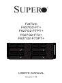
FatTwin
F627G2-FT+
F627G2-FTPT+
F627G2-F73+
F627G2-F73PT+
USER'S MANUAL
Revision 1.0b
®
The information in this User’s Manual has been carefully reviewed and is believed to be accurate.
The vendor assumes no responsibility for any inaccuracies that may be contained in this document,
makes no commitment to update or to keep current the information in this manual, or to notify any
person or organization of the updates. Please Note: For the most up-to-date version of this
manual, please see our web site at www.supermicro.com.
Super Micro Computer, Inc. ("Supermicro") reserves the right to make changes to the product
described in this manual at any time and without notice. This product, including software and
documentation, is the property of Supermicro and/or its licensors, and is supplied only under a
license. Any use or reproduction of this product is not allowed, except as expressly permitted by
the terms of said license.
IN NO EVENT WILL SUPERMICRO BE LIABLE FOR DIRECT, INDIRECT, SPECIAL, INCIDENTAL,
SPECULATIVE OR CONSEQUENTIAL DAMAGES ARISING FROM THE USE OR INABILITY TO
USE THIS PRODUCT OR DOCUMENTATION, EVEN IF ADVISED OF THE POSSIBILITY OF
SUCH DAMAGES. IN PARTICULAR, SUPERMICRO SHALL NOT HAVE LIABILITY FOR ANY
HARDWARE, SOFTWARE, OR DATA STORED OR USED WITH THE PRODUCT, INCLUDING THE
COSTS OF REPAIRING, REPLACING, INTEGRATING, INSTALLING OR RECOVERING SUCH
HARDWARE, SOFTWARE, OR DATA.
Any disputes arising between manufacturer and customer shall be governed by the laws of Santa
Clara County in the State of California, USA. The State of California, County of Santa Clara shall
be the exclusive venue for the resolution of any such disputes. Super Micro's total liability for all
claims will not exceed the price paid for the hardware product.
FCC Statement: This equipment has been tested and found to comply with the limits for a Class
A digital device pursuant to Part 15 of the FCC Rules. These limits are designed to provide
reasonable protection against harmful interference when the equipment is operated in a commercial
environment. This equipment generates, uses, and can radiate radio frequency energy and, if not
installed and used in accordance with the manufacturer’s instruction manual, may cause harmful
interference with radio communications. Operation of this equipment in a residential area is likely
to cause harmful interference, in which case you will be required to correct the interference at your
own expense.
California Best Management Practices Regulations for Perchlorate Materials: This Perchlorate
warning applies only to products containing CR (Manganese Dioxide) Lithium coin cells. “Perchlorate
Material-special handling may apply. See www.dtsc.ca.gov/hazardouswaste/perchlorate”
WARNING: Handling of lead solder materials used in this
product may expose you to lead, a chemical known to
the State of California to cause birth defects and other
reproductive harm.
Revision 1.0b
Release Date: April 25, 2014
Unless you request and receive written permission from Super Micro Computer, Inc., you may not
copy any part of this document.
Information in this document is subject to change without notice. Other products and companies
referred to herein are trademarks or registered trademarks of their respective companies or mark
holders.
Copyright © 2014 by Super Micro Computer, Inc.
All rights reserved.
Printed in the United States of America
Preface
Preface
About This Manual
This manual is written for professional system integrators and PC technicians.
It provides information for the installation and use of the FatTwin™
F627G2-FT+/FTPT+/F73+/F73PT+. Installation and maintainance should be
performed by experienced technicians only.
The FatTwin F627G2-FT+/FTPT+/F73+/F73PT+ is a high-end server based
on the F424BG-R1K62B 4U rackmount chassis and a dual processor
X9DRFF-iG+/iTG+/7G+/7TG+ serverboard. All models have an IPMI LAN port and
four serverboard nodes with six hot-swap 2.5" SAS or SATA Hard Disk Drives (HDD)
each per node. The F627G2-F73+ and F627G2-F73PT+ servers have SAS2 instead
of SATA drives, while both the F627G2-FTPT+ and F627G2-F73PT+ servers use
10-Gigabit LAN ports instead of Gigabit LAN ports.
Manual Organization
Chapter 1: Introduction
The first chapter provides a checklist of the main components included with the
server system and describes the main features of the X9DRFF-iG+/iTG+/7G+/7TG+
serverboards and the F424BG-R1K62B chassis.
Chapter 2: Server Installation
This chapter describes the steps necessary to install the FatTwin
F627G2-FT+/FTPT+/F73+/F73PT+ into a rack and check out the server
configuration prior to powering up the system. If your server was ordered without
processor and memory components, this chapter will refer you to the appropriate
sections of the manual for their installation.
Chapter 3: System Interface
Refer here for details on the system interface, which includes the functions and
information provided by the control panel on the chassis as well as other LEDs
located throughout the system.
Chapter 4: System Safety
You should thoroughly familiarize yourself with this chapter for a general overview of
safety precautions that should be followed when installing and servicing the FatTwin
F627G2-FT+/FTPT+/F73+/F73PT+.
iii
FatTwin F627G2-FT+/FTPT+/F73+/F73PT+ USER'S MANUAL
Chapter 5: Advanced Serverboard Setup
Chapter 5 provides detailed information on the X9DRFF-iG+/iTG+/7G+/7TG+
serverboards, including the locations and functions of connections, headers and
jumpers. Refer to this chapter when adding or removing processors or main memory
and when reconfiguring the serverboard.
Chapter 6: Advanced Chassis Setup
Refer to Chapter 6 for detailed information on the F424BG-R1K62B server chassis.
You should follow the procedures given in this chapter when installing, removing or
reconfiguring SATA or peripheral drives and when replacing system power supply
units and cooling fans.
Chapter 7: BIOS
The BIOS chapter includes an introduction to BIOS and provides detailed information
on running the CMOS Setup Utility.
Appendix A: BIOS Error Beep Codes
Appendix B: System Specifications
iv
FatTwin F627G2-FT+/FTPT+/F73+/F73PT+ USER'S MANUAL
Notes
v
FatTwin F627G2-FT+/FTPT+/F73+/F73PT+ USER'S MANUAL
Table of Contents
Chapter 1 Introduction
1-1
Overview ......................................................................................................... 1-1
1-2
Serverboard Features ..................................................................................... 1-2
Processors ...................................................................................................... 1-2
Memory ........................................................................................................... 1-2
Onboard SAS .................................................................................................. 1-2
Onboard Serial ATA ........................................................................................ 1-2
PCI Expansion Slots ....................................................................................... 1-3
I/O Ports .......................................................................................................... 1-3
Graphics Controller ......................................................................................... 1-3
Nuvoton WPCM450 Controller ....................................................................... 1-3
WPCM450R DDR2 Memory Interface ....................................................... 1-3
WPCM450R PCI System Interface ............................................................ 1-4
Other Features Supported by the WPCM BMC Controller ........................ 1-4
Power Supply .................................................................................................. 1-4
Super I/O ......................................................................................................... 1-4
1-3
Server Chassis Features ................................................................................ 1-5
System Power ................................................................................................. 1-5
SAS/SATA Subsystem..................................................................................... 1-5
I/O Ports .......................................................................................................... 1-5
Cooling System ............................................................................................... 1-5
Air Shrouds ..................................................................................................... 1-5
Mounting Rails ................................................................................................ 1-6
1-4
Advanced Power Management ....................................................................... 1-6
Intel® Intelligent Power Node Manager (NM) ................................................. 1-6
Manageability Engine (ME) ............................................................................. 1-6
1-5
Contacting Supermicro .................................................................................... 1-8
1-6
Fat Twin: System Notes .................................................................................. 1-9
Nodes .............................................................................................................. 1-9
System Power ................................................................................................. 1-9
SAS/SATA Backplane/Drives .......................................................................... 1-9
Chapter 2 Server Installation
2-1
Overview ......................................................................................................... 2-1
2-2
Unpacking the System .................................................................................... 2-1
2-3
Preparing for Setup ......................................................................................... 2-1
2-4
Warnings and Precautions .............................................................................. 2-2
vi
Table of Contents
Choosing a Setup Location ............................................................................. 2-2
Rack Precautions ............................................................................................ 2-2
Server Precautions.......................................................................................... 2-2
Rack Mounting Considerations ....................................................................... 2-3
Ambient Operating Temperature ................................................................ 2-3
Reduced Airflow ......................................................................................... 2-3
Mechanical Loading ................................................................................... 2-3
Circuit Overloading ..................................................................................... 2-3
Reliable Ground ......................................................................................... 2-4
2-5
Rack Mounting Instructions ............................................................................. 2-4
Identifying the Sections of the Rack Rails ...................................................... 2-4
Adjusting the Rails .......................................................................................... 2-4
Locking Tabs ................................................................................................... 2-5
Installing the Rails on a Rack ......................................................................... 2-6
Chassis Installation ......................................................................................... 2-7
2-6
Checking the Serverboard Setup .................................................................... 2-8
2-7
Checking the Drive Bay Setup ........................................................................ 2-9
Chapter 3 System Interface
3-1
Overview ......................................................................................................... 3-1
3-2
SCF424 Rear I/O Control Panel ..................................................................... 3-1
3-4
Drive Carrier LEDs .......................................................................................... 3-3
Control Panel Buttons ..................................................................................... 3-2
Chapter 4 Standardized Warning Statements for AC Systems
4-1
About Standardized Warning Statements ....................................................... 4-1
Warning Definition ........................................................................................... 4-1
Installation Instructions.................................................................................... 4-4
Circuit Breaker ................................................................................................ 4-5
Power Disconnection Warning ........................................................................ 4-6
Equipment Installation ..................................................................................... 4-8
Restricted Area................................................................................................ 4-9
Battery Handling............................................................................................ 4-10
Redundant Power Supplies .......................................................................... 4-12
Backplane Voltage ........................................................................................ 4-13
Comply with Local and National Electrical Codes ........................................ 4-14
Product Disposal ........................................................................................... 4-15
Hot Swap Fan Warning ................................................................................. 4-16
Power Cable and AC Adapter ...................................................................... 4-18
vii
FatTwin F627G2-FT+/FTPT+/F73+/F73PT+ USER'S MANUAL
Chapter 5 Advanced Motherboard Setup
5-1
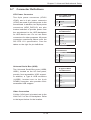
Handling the Motherboard .............................................................................. 5-1
Precautions ..................................................................................................... 5-1
Unpacking ....................................................................................................... 5-1
5-2
Connecting Cables .......................................................................................... 5-2
Connecting Power Cables .............................................................................. 5-2
Connecting Data Cables ................................................................................. 5-2
5-3
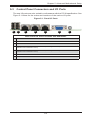
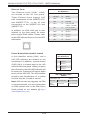
Control Panel Connectors and I/O Ports ........................................................ 5-3
5-4
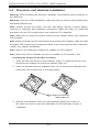
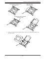
Processor and Heatsink Installation................................................................ 5-4
Installing a CPU Heatsink ............................................................................... 5-8
Removing the Heatsink ................................................................................... 5-8
5-5
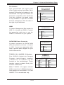
Installing Memory ............................................................................................ 5-9
Removing Memory Modules ......................................................................... 5-10
Memory Support ............................................................................................ 5-10
5-6
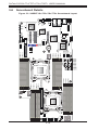
Serverboard Details ...................................................................................... 5-16
5-7
Connector Definitions .................................................................................... 5-19
5-8
Jumper Settings ............................................................................................ 5-23
5-9
Onboard Indicators........................................................................................ 5-25
Explanation of Jumpers ................................................................................ 5-23
5-10
Serial ATA Connections ................................................................................. 5-27
5-11
Installing Drivers............................................................................................ 5-28
SuperDoctor III .............................................................................................. 5-29
5-12
Serverboard Battery ...................................................................................... 5-31
Chapter 6 Advanced Chassis Setup
6-1
Static-Sensitive Devices .................................................................................. 6-1
Precautions ..................................................................................................... 6-1
Unpacking ....................................................................................................... 6-1
6-2
Control Panel .................................................................................................. 6-2
6-3
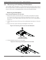
Removing the Power Cord .............................................................................. 6-3
6-4
Removing Nodes from the Chassis ................................................................ 6-3
6-5
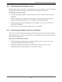
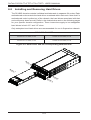
Installing and Removing Hard Drives ............................................................. 6-4
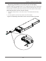
Removing Hard Drives from the Front of the Node ........................................ 6-5
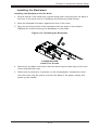
Installing Hard Drives into the Drive Carriers ................................................. 6-6
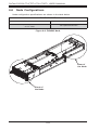
6-6
Node Configurations ....................................................................................... 6-8
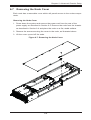
6-7
Removing the Node Cover.............................................................................. 6-9
6-8
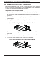
Removing and Installing the Backplane........................................................ 6-10
Removing the Backplane .............................................................................. 6-10
Installing the Backplane .................................................................................6-11
viii
Table of Contents
6-9
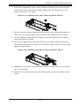
Power Distributor Board Replacement.......................................................... 6-12
6-10
Installing the Motherboard ........................................................................... 6-14
Compatible Motherboards ............................................................................. 6-14
Permanent and Optional Standoffs ............................................................... 6-14
6-11
Installing Front and Rear Expansion Cards .................................................. 6-16
PCIE Slot Setup ............................................................................................ 6-16
F424BG PCIE Slot Configurations ................................................................ 6-16
Installing a Low-Profile Expansion Card ....................................................... 6-17
6-12
Installing Internal GPUs ................................................................................ 6-18
Installing Front 10.5" GPUs into the GPU Bracket ...................................... 6-18
Installing a Front 10.5" GPU into the Node ................................................. 6-20
Installing Rear 13" GPUs into the Node ...................................................... 6-20
Installing Rear 13" GPUs into a Node ......................................................... 6-22
6-13
Installing the Air Shroud ................................................................................ 6-23
6-14
Checking the Airflow .................................................................................... 6-24
6-15
Replacing System Fans ................................................................................ 6-25
6-16
Replacing the Power Supply ......................................................................... 6-26
Air Shrouds ................................................................................................... 6-23
Installation Complete..................................................................................... 6-24
Power Supply Replacement .......................................................................... 6-26
Chapter 7 BIOS
7-1
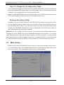
Introduction...................................................................................................... 7-1
Starting BIOS Setup Utility .............................................................................. 7-1
How To Change the Configuration Data ......................................................... 7-2
Starting the Setup Utility ................................................................................. 7-2
7-2
Main Setup ...................................................................................................... 7-2
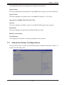
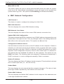
7-3
Advanced Setup Configurations...................................................................... 7-3
7-4
Event Logs .................................................................................................... 7-23
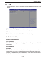
7-5
IPMI ............................................................................................................... 7-25
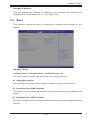
7-6
Boot ............................................................................................................... 7-27
7-7
Security ......................................................................................................... 7-28
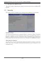
7-8
Save & Exit ................................................................................................... 7-29
Appendix A System Specifications
ix
FatTwin F627G2-FT+/FTPT+/F73+/F73PT+ USER'S MANUAL
Notes
x
Chapter 1: Introduction
Chapter 1
Introduction
1-1
Overview
The FatTwin F627G2-FT+/FTPT+/F73+/F73PT+ is a high-end server comprised
of two main subsystems: the F424BG-R1K62B 4U server chassis and the
X9DRFF-iG+/iTG+/7G+/7TG+ dual processor serverboard in four hot-swap nodes.
Please refer to our web site for information on operating systems that have been
certified for use with the system (www.supermicro.com).
In addition to the serverboard and chassis, various hardware components have
been included with the SuperServer F627G2-FT+/FTPT+/F73+/F73PT+ server, as
listed below:
•
•
•
•
•
Heatsinks:
Four (4) 1U passive CPU heat sinks with narrow ILM (SNK-P0047PS)
Four (4) 1U passive CPU heat sinks for 1U GPU server (SNK-P0047PSC)
Power Adapter Cards and Cables:
Four (4) FatTwin MB tray midplanes (BPN-ADP-F418L-O-P)
Four (4) backplanes for 2U GPU adapter cards (BPN-ADP-2UGPU-O-P)
SATA Backplane:
Four (4) backplanes each for six (6) 2.5" HDD (BPN-SAS-F424-B6)
Four (4) 40-cm and 45-cm 18AWG 8-pin male to two 4-pin male power cables
(CBL-0460L-02)
Twenty-Four (24) 21-cm 30AWG SATA S-S cables (CBL-0473L)
Eight (8) 27-cm 8-pin to 8-pin ribbon SGPIO cables with tube (CBL-0157L-02)
Twenty-four (24) black hot swap 2.5" HDD trays (MCP-220-00098-0B)
Riser Cards:
Four (4) riser cards (RSC-R2UFF-2E16B-O-P)
Four (4) riser cards (RSC-R2UFF-E16A-O-P)
One (1) F418/F424 rail set (MCP-290-41803-0N)
Note: For your system to work properly, please follow the links below to download
all necessary drivers/utilities and the user’s manual for your server.
•
•
•
Supermicro product manuals: http://www.supermicro.com/support/manuals/
Product drivers and utilities: ftp://ftp.supermicro.com
Product safety information:
http://super-dev/about/policies/safety_information.cfm
1-1
FatTwin F627G2-FT+/FTPT+/F73+/F73PT+ USER'S MANUAL
•
1-2
If you have any questions, please contact our support team at:
[email protected]
Serverboard Features
At the heart of the FatTwin F627G2-FT+/FTPT+/F73+/F73PT+ lies the
X9DRFF-iG+/iTG+/7G+/7TG+, a dual processor serverboard based on the Intel®
C602 chipset. Below are the main features of the serverboard. (See Figure 1-1 for
a block diagram of the chipset.)
Processors
The X9DRFF-iG+/iTG+/7G+/7TG+ supports single or dual Intel® E5-2600 series
processors in Socket R LGA 2011 sockets. Please refer to the serverboard
description pages on our web site for a complete listing of supported processors
(www.supermicro.com).
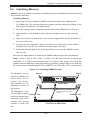
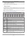
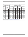
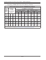
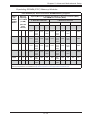
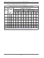
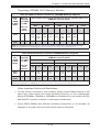
Memory
The X9DRFF-iG+/iTG+/7G+/7TG+ has sixteen (16) memory sockets that
can support up to 512 GB of ECC registered RDIMMs or up to 128 GB of
unbuffered ECC/non-ECC UDIMMs in DDR3-1600/1333/1066/800 MHz speed,
1 GB, 2 GB, 4 GB, 8 GB, 16 GB or 32 GB size, and .at 1.35 or 1.5 voltages.
Please refer to Chapter 5 for installing memory.
Note: For the latest CPU/memory updates, please refer to our website at
http://www.supermicro.com/products/motherboard.
Onboard SAS
An LSI 2308 SAS controller provides eight SAS2 ports. The SAS drives are
connected to a backplane that provides power, bus termination and configuration
settings. RAID 0, 1, and 10 are supported.
Note: The operating system you use must have RAID support to enable the
hotswap capability and RAID function of the SAS drives.
Onboard Serial ATA
A SATA controller is integrated into the chipset to provide a six-port SATA
subsystem. Two of the ports support SATA 3.0 (RAID 0 and 1) and four support
SATA 2.0 (RAID 0, 1, 5 and 10). See Chapter 5 for details.
Note: The operating system you use must have RAID support to enable the
hotswap capability and RAID function of the SATA drives.
1-2
Chapter 1: Introduction
PCI Expansion Slots
Each node in the the FatTwin F627G2-FT+/FTPT+/F73+/F73PT+ has
3x PCI-E 3.0 x16 (that support three double-width GPU/MIC expansion cards) and
2x PCI-E 3.0 x8 expansion slots. Two riser cards are provided for each node for
use with these expansion slots.
I/O Ports
The color-coded I/O ports located at the front of each node in the server
include a VGA (monitor) port, two USB 2.0 ports, two 1 Gb Ethernet ports (the
X9DRFF-iTG+/X9DRFF-7TG+ serverboard's feature two 10 Gb Ethernet ports
instead) and one dedicated IPMI LAN port.
Note: For IPMI Configuration Instructions, please refer to the Embedded IPMI
Configuration User's Guide available @ http://www.supermicro.com/support/
manuals/.
Graphics Controller
The X9DRFF-iG+/iTG+/7G+/7TG+ features an integrated Matrox G200ew, 16 MB
DDR2 graphics controller.
Nuvoton WPCM450 Controller
Note: The term "IPMI controller" and the term "BMC controller" can be
interchangeably in this section.
used
The Nuvoton WPCM450R Controller, a Baseboard Management Controller (BMC),
supports 2D/VGA-compatible Graphic Cores with PCI interface, creating multi-media
virtualization via Keyboard/Video/Mouse Redirection (KVMR). The WPCM450R
Controller is ideal for remote system management.
The WPCM450R Controller interfaces with the host system via PCI connections
to communicate with the graphics cores. It supports USB 2.0 and 1.1 for remote
keyboard/mouse/virtual media emulation. It also provides LPC interface support to
control Super IO functions. The WPCM450R Controller is connected to the network
via an external Ethernet PHY module or shared NCSI connections.
The WPCM450R communicates with onboard components via six SMBus
interfaces, PECI (Platform Environment Control Interface) buses, and General
Purpose I/O ports.
WPCM450R DDR2 Memory Interface
The WPCM450R supports a 16-bit DDR2 memory module with a speed of up to 220
MHz. For best signal integrity, the WPCM450R provides point-to-point connection.
1-3
FatTwin F627G2-FT+/FTPT+/F73+/F73PT+ USER'S MANUAL
WPCM450R PCI System Interface
The WPCM450R provides 32-bit, 33 MHz 3.3V PCI interface, which is compliant
with the PCI Local Bus Specification Rev. 2.3. The PCI system interface connects
to the onboard PCI Bridge used by the graphics controller.
Other Features Supported by the WPCM BMC Controller
The WPCM450R supports the following features:
•
•
•
•
•
•
•
•
•
•
•
•
•
•
IPMI 2.0
Serial over LAN
KVM over LAN
LAN Alerting-SNMP Trap
Event Log
X-Bus parallel interface for I/O expansion
Multiple ADC inputs, Analog and Digital Video outputs
SPI Flash Host BIOS and firmware bootstrap program supported
Reduced Media Independent Interface (RMII)
OS (Operating System) Independency
Provides remote Hardware Health Monitoring via IPMI. Key features
Provides Network Management Security via remote access/console redirection.
Supports the following Management tools: IPMIView, CLI (Command Line
Interface)
RMCP+ protocol supported
Note: For more information on IPMI configuration, please refer to the IPMI User's
Guide posted on our website at http://www.supermicro.com/support/manuals/.
Power Supply
Please connect the power cable from the SMC-Proprietary Adaptor (BPN-ADPF418L) to the motherboard in order to provide power to the system.
Super I/O
The Super I/O provides functions that comply with ACPI (Advanced Configuration
and Power Interface), which includes support of legacy and ACPI power
management through an SMI or SCI function pin. It also features auto power
management to reduce power consumption.
1-4
Chapter 1: Introduction
1-3
Server Chassis Features
The following is a general outline of the main features of the F424BG server chassis.
System Power
The F424BG chassis model includes four high-efficiency 94%+ Platinum certified
redundant 1620 Watt power supplies. In the unlikely event your power supply fails,
replacement is simple and can be accomplished without tools.
SAS/SATA Subsystem
The F424BG supports up to six (6) hot-swap 2.5" SAS/SATA drives in trays for each
node for a total of twenty-four (24) drives. These drives are hot-swappable units and
are connected to two backplanes (that provides power and control).
Note: The operating system you use must have RAID support to enable the
hot-swap capability of the drives. For more information, visit our Web site at:
http://www.supermicro.com.
I/O Ports
The F424BG is an proprietary form factor chassis designed to be used in a 4U
rackmount configuration. The F424BG chassis provides three low-profile add-on
card slots, a VGA port, two USB 2.0 ports, one IPMI Ethernet port and two gigabit
Ethernet ports per node.
Cooling System
The F424BG chassis accepts eight (8) 8-cm system fans powered from either the
backpane or the serverboards. When one of the motherboard nodes is removed,
another motherboard will continue to operate the fans.
Air Shrouds
The F424BG chassis requires mylar air shrouds for each node to direct the airflow
where cooling is needed. The air shroud will differ for different motherboards. If using
a motherboard which is not the default in the chassis, refer to the optional parts in
the Appendix of this manual, or the Supermicro Web site at www.supermicro.com
to puchase the proper air shroud.
1-5
FatTwin F627G2-FT+/FTPT+/F73+/F73PT+ USER'S MANUAL
Mounting Rails
The F424BG includes a set of rails, and can be placed in a rack for secure storage
and use. To setup your rack, follow the step-by-step instructions included in this
manual.
1-4
Advanced Power Management
Intel® Intelligent Power Node Manager (NM)
The Intel® Intelligent Power Node Manager (IPNM) provides your system with
real-time thermal control and power management for maximum energy efficiency.
Although IPNM Specification Version 1.5 is supported by the BMC (Baseboard
Management Controller), your system must also have IPNM-compatible
Manageability Engine (ME) firmware installed to use this feature.
Manageability Engine (ME)
The Manageability Engine, which is an ARC controller embedded in the IOH (I/O
Hub), provides Server Platform Services (SPS) to your system. The services
provided by SPS are different from those proveded by the ME on client platforms.
1-6
Chapter 1: Introduction
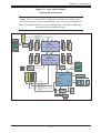
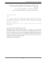
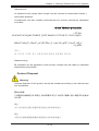
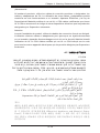
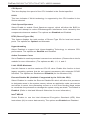
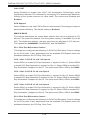
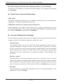
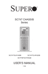
Figure 1-1. Intel C602 Chipset:
System Block Diagram
Gen3 x8
LAN
X540
I350 (2 ports)
PE3
J4
PCI-Ex8 SLOT
PCI-Ex4 in x8 SLOT
DDR3 DIMM
A
DMI
AT25321
SPI
SATA
DMI
3/1.5
3/1.5
3/1.5
3/1.5
6/3/1.5
6/3/1.5
AHCI
PCH C602
SCU
SATA
PEG2_5:7
PCI-32bit
Gen3 x8 (8~15)
USB
USB
PEG2_0:4
Gen3 x16
LPC
Gen3 x8 (0~7)
WPCM450
VGA BMC
VGA CONN PHY
RTL8201F
LAN
1-7
TPM
Gen2 x4
SATA2 #6
SATA2 #5
SATA2 #4
SATA2 #3
SATA3 #2
SATA3 #1
SATA2 #1 DOM
0
1
2
Type A
J3
#1
#2
DDR3 DIMM
CPU0
Front (I/O Side)
#1
#2
Single
J2
B
Single
J1
G
DDR3 DIMM
P0
Gen3 x8 (0~7)
PCI-Ex8 SLOT
RJ45
#1
#2
P1
E5-2600 Series Processor
PE2
#1
#2
QPI
QPI
P1
D
PE1
RJ45
H
CPU1
Rear (Fan Side)
DDR3 DIMM
DDR3 DIMM
#1
#2
C
DMI
E5-2600 Series Processor
P0
#1
#2
PE3
DDR3 DIMM
PE2
Gen2 x4
E
PE1
F
DDR2
SAS2308
#1
#2
DDR3 DIMM
#1
#2
DDR3 DIMM
SAS
Gen3 x16 x16
PCI-Ex16
Proprietary SLOT
SAS2 #1
SAS2 #2
SAS2 #3
SAS2 #4
SAS2 #5
SAS2 #6
SAS2 #7
SAS2 #8
PCI-Ex16x16
Proprietary SLOT
Note: This is a general block diagram and may not exactly represent the features on your motherboard. See the previous pages for
the actual specifications of your motherboard. This block diagram is
intended for your reference only.
FatTwin F627G2-FT+/FTPT+/F73+/F73PT+ USER'S MANUAL
1-5
Contacting Supermicro
Headquarters
Address:
Super Micro Computer, Inc.
980 Rock Ave.
San Jose, CA 95131 U.S.A.
Tel:
+1 (408) 503-8000
Fax:
+1 (408) 503-8008
Email:
[email protected] (General Information)
Web Site:
www.supermicro.com
[email protected] (Technical Support)
Europe
Address:
Super Micro Computer B.V.
Het Sterrenbeeld 28, 5215 ML
's-Hertogenbosch, The Netherlands
Tel:
+31 (0) 73-6400390
Fax:
+31 (0) 73-6416525
Email:
[email protected] (General Information)
[email protected] (Technical Support)
[email protected] (Customer Support)
Web Site:
www.supermicro.nl
Asia-Pacific
Address:
Super Micro Computer, Inc.
3F, No. 150, Jian 1st Rd.
Zhonghe Dist., New Taipei City 235
Taiwan (R.O.C)
Tel:
+886-(2) 8226-3990
Fax:
+886-(2) 8226-3992
Email:
[email protected]
Web Site:
www.supermicro.com.tw
1-8
Chapter 1: Introduction
1-6
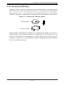
Fat Twin: System Notes
As a FatTwin configuration, the FatTwin F627G2-FT+/FTPT+/F73+/F73PT+ is a
unique server system. With four system boards incorporated into a single chassis
acting as four separate nodes, there are several points you should keep in mind.
Nodes
Each of the four serverboards act as a separate node in the system. As independant
nodes, each may be powered off and on without affecting the others. In addition,
each node is a hot-swappable unit that may be removed from the rear of the chassis.
The nodes are connected to the server backplane by means of an adapter card.
Note: A guide pin is located between the upper and lower nodes on the inner chassis
wall. This guide pin also acts as a “stop” when a node is fully installed. If too much
force is used when inserting a node this pin may break off. Take care to slowly slide
a node in until you hear the “click” of the locking tab seating itself.
System Power
Four 1620 Watt power supplies are used to provide the power for all serverboards.
Each serverboard however, can be shut down independently of the other with the
power button on its own control panel.
SAS/SATA Backplane/Drives
As a system, the FatTwin F627G2-FT+/FTPT+/F73+/F73PT+ supports the use of
twenty-four (24) 2.5" Hot-swap SAS/SATA drives. Each of the four backplanes in
the system works to apply system-based control for power and fan speed functions,
yet at the same time logically connects a set of six SAS/SATA drives to each
backplane/serverboard. Consequently, RAID setup is limited to a six-drive scheme
(RAID cannot be spread across all drives). See Chapter 6 for the logical hard drive
and node configuration.
1-9
FatTwin F627G2-FT+/FTPT+/F73+/F73PT+ USER'S MANUAL
Notes
1-10
Chapter 2: Server Installation
Chapter 2
Server Installation
2-1
Overview
This chapter provides a quick setup checklist to get your FatTwin
F627G2-FT+/FTPT+/F73+/F73PT+ up and running. Following these steps in the
order given should enable you to have the system operational within a minimum
amount of time. This quick setup assumes that your system has come to you with the
processors and memory preinstalled. If your system is not already fully integrated
with a serverboard, processors, system memory etc., please turn to the chapter or
section noted in each step for details on installing specific components.
2-2
Unpacking the System
You should inspect the box the FatTwin F627G2-FT+/FTPT+/F73+/F73PT+ was
shipped in and note if it was damaged in any way. If the server itself shows damage
you should file a damage claim with the carrier who delivered it.
Decide on a suitable location for the rack unit that will hold the FatTwin
F627G2-FT+/FTPT+/F73+/F73PT+. It should be situated in a clean, dust-free area
that is well ventilated. Avoid areas where heat, electrical noise and electromagnetic
fields are generated. You will also need it placed near a grounded power outlet.
Read the Rack and Server Precautions in the next section.
2-3
Preparing for Setup
The box the FatTwin F627G2-FT+/FTPT+/F73+/F73PT+ was shipped in should
include two sets of rail assemblies, two rail mounting brackets and the mounting
screws you will need to install the system into the rack. Follow the steps in the
order given to complete the installation process in a minimum amount of time.
Please read this section in its entirety before you begin the installation procedure
outlined in the sections that follow.
2-1
FatTwin F627G2-FT+/FTPT+/F73+/F73PT+ USER'S MANUAL
2-4
Warnings and Precautions
Choosing a Setup Location
•
•
•
Leave enough clearance in front of the rack to enable you to open the front door
completely (~25 inches) and approximately 30 inches of clearance in the back
of the rack to allow for sufficient airflow and ease in servicing.
This product is for installation only in a Restricted Access Location (dedicated
equipment rooms, service closets and the like).
This product is not suitable for use with visual display work place devices
acccording to §2 of the the German Ordinance for Work with Visual Display Units.
Rack Precautions
•
•
•
•
Ensure that the leveling jacks on the bottom of the rack are fully extended to
the floor with the full weight of the rack resting on them.
In single rack installation, stabilizers should be attached to the rack. In multiple
rack installations, the racks should be coupled together.
Always make sure the rack is stable before extending a component from the
rack.
You should extend only one component at a time - extending two or more
simultaneously may cause the rack to become unstable.
Server Precautions
•
•
•
•
•
•
Review the electrical and general safety precautions in Chapter 4.
Determine the placement of each component in the rack before you install the
rails.
Install the heaviest server components on the bottom of the rack first, and then
work up.
Use a regulating uninterruptible power supply (UPS) to protect the server from
power surges, voltage spikes and to keep your system operating in case of a
power failure.
Allow any hot plug drives and power supply modules to cool before touching
them.
Always keep the rack's front door and all panels and components on the servers
closed when not servicing to maintain proper cooling.
2-2
Chapter 2: Server Installation
Rack Mounting Considerations
Warning! To prevent bodily injury when mounting or servicing this unit in a
rack, you must take special precautions to ensure that the system remains stable.
The following guidelines are provided to ensure your safety:
•
•
•
This unit should be mounted at the bottom of the rack if it is the only unit in
the rack.
When mounting this unit in a partially filled rack, load the rack from the bottom
to the top with the heaviest component at the bottom of the rack.
If the rack is provided with stabilizing devices, install the stabilizers before
mounting or servicing the unit in the rack.
Ambient Operating Temperature
If installed in a closed or multi-unit rack assembly, the ambient operating
temperature of the rack environment may be greater than the ambient temperature
of the room. Therefore, consideration should be given to installing the equipment
in an environment compatible with the manufacturer’s maximum rated ambient
temperature (Tmra).
Reduced Airflow
Equipment should be mounted into a rack so that the amount of airflow required
for safe operation is not compromised.
Mechanical Loading
Equipment should be mounted into a rack so that a hazardous condition does not
arise due to uneven mechanical loading.
Circuit Overloading
Consideration should be given to the connection of the equipment to the power
supply circuitry and the effect that any possible overloading of circuits might have
on overcurrent protection and power supply wiring. Appropriate consideration of
equipment nameplate ratings should be used when addressing this concern.
2-3
FatTwin F627G2-FT+/FTPT+/F73+/F73PT+ USER'S MANUAL
Reliable Ground
A reliable ground must be maintained at all times. To ensure this, the rack
itself should be grounded. Particular attention should be given to power supply
connections other than the direct connections to the branch circuit (i.e. the use of
power strips, etc.).
2-5
Rack Mounting Instructions
This section provides information on installing the chassis into a rack unit with the
rails provided. There are a variety of rack units on the market, which may mean that
the assembly procedure will differ slightly from the instructions provided. You should
also refer to the installation instructions that came with the rack unit you are using.
Note: This rail will fit a rack between 26.5" and 36.4" deep. The SCF418 is not
designed for installation into a Telco post-style rack unit.
Warning: Do not pick up the server with the front handles. They are
designed to pull the system from a rack only.
Stability Hazard: The rack stabilizing mechanism must be in place, or the
rack must be bolted to the floor before you slide the unit out for servicing. Failure
to stabilize the rack can cause the rack to tip over.
Warning: When initially installing the server to a rack, test that the rail locking tabs
engage to prevent the server from being overextended. Have a rack lift in place as
a precaution in case the test fails.
Warning: In any instance of pulling the system from the rack, always use a rack
lift and follow all associated safety precautions.
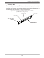
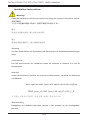
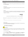
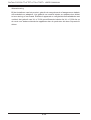
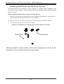
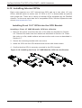
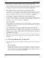
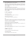
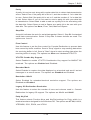
Identifying the Sections of the Rack Rails
The chassis package includes two rail assemblies in the rack mounting kit. Each
assembly consists of two sections: A front section which secures to the front post
of the rack and a rear section which adjusts in length and secures to the rear post
of the rack. These assemblies are specifically designed for the left and right side
of the chassis (see Figure 2-1).
Adjusting the Rails
Each rail assembly has an adjusting screw. loosening this screw allows you to adjust
the length of the rail to fit a variety of rack sizes.
2-4
Chapter 2: Server Installation
Locking Tabs
Each inner rail has a locking tab. This tab locks the chassis into place when installed
and pushed fully into the rack. These tabs also lock the chassis in place when fully
extended from the rack. This prevents the server from coming completely out of
the rack when when the chassis is pulled out for servicing.
Figure 2-1: Identifying the Outer Rail and Inner Rails
(Left Rail Assembly Shown)
Locking Tab
Inner Rail
Outer Rail
This Side Faces
Outward
Adjusting Screw
2-5
FatTwin F627G2-FT+/FTPT+/F73+/F73PT+ USER'S MANUAL
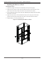
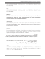
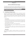
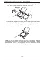
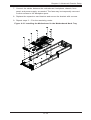
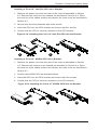
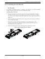
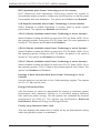
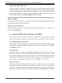
Installing the Rails on a Rack
Installing the Rails
1. Adjust the length of both rails as described on the previous page.
2. Align the front section of the outer rail with the slots on the front post of the
rack. Secure the front of the outer rail to the rack with two screws.
3. Pull out the rear section of the outer rail, adjusting the length until it fits within
the posts of the rack.
4. Align the rear section of the rail with the slots on the rear post of the rack.
Secure the rear of the outer rail to the rear of the rack with two screws.
5. Repeat steps 1-4 for the remaining rail.
Figure 2-2: Attaching the Rails to a Rack
2-6
Chapter 2: Server Installation
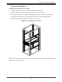
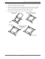
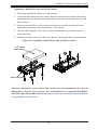
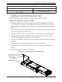
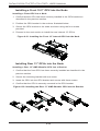
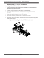
Chassis Installation
Installing the Chassis into a Rack
1. Confirm that the rails are correctly installed on the rack.
2. Align the bottom of the chassis with the bottom of the rails.
3. Insert the chassis into the rails, keeping the pressure even on both sides,
pushing the chassis into the rack until it clicks into the locked position.
4. Secure the chassis handles to the front of the rack.
Figure 2-3: Installing into a Rack
Note: The figure above is for illustration purposes only. Always install servers to
the bottom of the rack first.
2-7
FatTwin F627G2-FT+/FTPT+/F73+/F73PT+ USER'S MANUAL
2-6
Checking the Serverboard Setup
After you install the FatTwin F627G2-FT+/FTPT+/F73+/F73PT+ in the rack, you will
need to open the unit to make sure the serverboard is properly installed and all the
connections have been made.
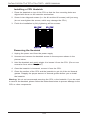
Accessing the inside of the System
Before operating the server for the first time, it is important to remove the protective
film covering the top of the chassis, in order to allow for proper ventilation and
cooling.
Warning: Except for short periods of time, do NOT operate the server without
the cover in place. The chassis cover must be in place to allow proper airflow
and prevent overheating.
Checking the Components and Setup
1. You may have one or two processors already installed into the serverboard.
Each processor needs its own heat sink. See Chapter 5 for instructions on
processor and heat sink installation.
2. Your FatTwin F627G2-FT+/FTPT+/F73+/F73PT+ server system may have
come with system memory already installed. Make sure all DIMMs are fully
seated in their slots. For details on adding system memory, refer to Chapter
5.
3. If desired, you can install add-on cards to the system. See Chapter 5 for
details on installing PCI add-on cards.
4. Make sure all power and data cables are properly connected and not blocking
the chassis airflow. Also make sure that no cables are positioned in front of
the fans. See Chapter 5 for details on cable connections.
2-8
Chapter 2: Server Installation
2-7
Checking the Drive Bay Setup
Next, you should check to make sure the peripheral drives and the SATA drives
have been properly installed and all connections have been made.
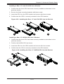
Checking the Drives
1. All drives are accessable from the front of the server. A hard drive can be
installed and removed from the front of the chassis without removing the top
chassis cover.
2. Depending upon your system's configuration, your system may have one or
more drives already installed. If you need to install hard drives, please refer to
Chapter 6.
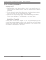
Checking the Airflow
1. Make sure there are no objects to obstruct airflow in and out of the server. In
addition, if you are using a front bezel, make sure the bezel's filter is replaced
periodically.
2. Do not operate the server without drives or drive trays in the drive bays. Use
only recommended server parts.
3. Make sure that no wires or foreign objects obstruct air flow through the
chassis. Pull all excess cabling out of the airflow path or use shorter cables.
The control panel LEDs inform you of the system status. See “Chapter 3
System Interface” for details on the LEDs and the control panel buttons.
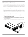
Providing Power
1. Plug the power cord(s) from the power supply unit(s) into a high-quality
power strip that offers protection from electrical noise and power surges. It is
recommended that you use an uninterruptible power supply (UPS).
2. Depress the power on button on the front of the chassis.
2-9
FatTwin F627G2-FT+/FTPT+/F73+/F73PT+ USER'S MANUAL
Notes
2-10
Chapter 3: System Interface
Chapter 3
System Interface
3-1
Overview
There are several buttons and LEDs are located on each of the motherboard nodes
and on the drive carriers to keep you constantly informed of the overall status of
the system.
This chapter explains the meanings of all LED indicators and the appropriate response you may need to take.
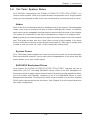
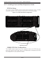
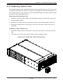
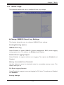
3-2
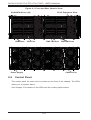
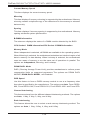
SCF424 Rear I/O Control Panel
Figure 3-1: F424BG Front I/O Control Panel
3-1
FatTwin F627G2-FT+/FTPT+/F73+/F73PT+ USER'S MANUAL
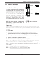
Control Panel Buttons
•
•
Power: The main power button on each of the four control panels is used to
apply or remove power from the power supply to each of the four systems in
the chassis. Turning off system power with this button removes the main power,
but keeps standby power supplied to the system. Therefore, you must unplug
system before servicing. The power button has a built-in LED which will turn
green when the power is on
UID: When used with a UID compatible motherboard, the UID button is used
to turn on or off the blue light function of the LED. This is built into the front
side of the UID button and at the rear end of each motherboard node, for those
motherboards which support it. Once the blue light is activated, the unit can be
easily located in very large racks and server banks.
3-2
Chapter 3: System Interface
3-4
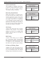
Drive Carrier LEDs
The F424BG chassis supports hot-swappable 2.5" SAS/SATA drives include the
following LED indicators.
SAS/SATA Drives
Each SAS/SATA drive carrier has two LEDs.
•
•
Blue: Each Serial ATA drive carrier has a blue LED. When illuminated, this blue
LED (on the front of the SATA drive carrier) indicates drive activity. A connection
to the SATA backplane enables this LED to blink on and off when that particular
drive is being accessed.
Red: The red LED to indicate an SAS/SATA drive failure. If one of the SAS/
SATA drives fail, you should be notified by your system management software.
SCSI Drives
This chassis does not support SCSI drives.
3-3
FatTwin F627G2-FT+/FTPT+/F73+/F73PT+ USER'S MANUAL
Notes
3-4
Chapter 4: Warning Statements for AC Systems
Chapter 4
Standardized Warning Statements for AC Systems
4-1
About Standardized Warning Statements
The following statements are industry standard warnings, provided to warn the user
of situations which have the potential for bodily injury. Should you have questions
or experience difficulty, contact Supermicro's Technical Support department
for assistance. Only certified technicians should attempt to install or configure
components.
Read this appendix in its entirety before installing or configuring components in the
Supermicro chassis.
These warnings may also be found on our web site at http://www.supermicro.com/
about/policies/safety_information.cfm.
Warning Definition
Warning!
This warning symbol means danger. You are in a situation that could cause bodily
injury. Before you work on any equipment, be aware of the hazards involved with
electrical circuitry and be familiar with standard practices for preventing accidents.
警告の定義
この警告サインは危険を意味します。
人身事故につながる可能性がありますので、いずれの機器でも動作させる前に、
電気回路に含まれる危険性に注意して、標準的な事故防止策に精通して下さい。
此警告符号代表危险。
您正处于可能受到严重伤害的工作环境中。在您使用设备开始工作之前,必须充分
意识到触电的危险,并熟练掌握防止事故发生的标准工作程序。请根据每项警告结
尾的声明号码找到此设备的安全性警告说明的翻译文本。
此警告符號代表危險。
您正處於可能身體可能會受損傷的工作環境中。在您使用任何設備之前,請注意觸
電的危險,並且要熟悉預防事故發生的標準工作程序。請依照每一注意事項後的號
碼找到相關的翻譯說明內容。
4-1
FatTwin F627G2-FT+/FTPT+/F73+/F73PT+ USER'S MANUAL
Warnung
WICHTIGE SICHERHEITSHINWEISE
Dieses Warnsymbol bedeutet Gefahr. Sie befinden sich in einer Situation, die zu
Verletzungen führen kann. Machen Sie sich vor der Arbeit mit Geräten mit den
Gefahren elektrischer Schaltungen und den üblichen Verfahren zur Vorbeugung
vor Unfällen vertraut. Suchen Sie mit der am Ende jeder Warnung angegebenen
Anweisungsnummer nach der jeweiligen Übersetzung in den übersetzten
Sicherheitshinweisen, die zusammen mit diesem Gerät ausgeliefert wurden.
BEWAHREN SIE DIESE HINWEISE GUT AUF.
INSTRUCCIONES IMPORTANTES DE SEGURIDAD
Este símbolo de aviso indica peligro. Existe riesgo para su integridad física. Antes
de manipular cualquier equipo, considere los riesgos de la corriente eléctrica y
familiarícese con los procedimientos estándar de prevención de accidentes. Al
final de cada advertencia encontrará el número que le ayudará a encontrar el texto
traducido en el apartado de traducciones que acompaña a este dispositivo.
GUARDE ESTAS INSTRUCCIONES.
IMPORTANTES INFORMATIONS DE SÉCURITÉ
Ce symbole d'avertissement indique un danger. Vous vous trouvez dans une
situation pouvant entraîner des blessures ou des dommages corporels. Avant
de travailler sur un équipement, soyez conscient des dangers liés aux circuits
électriques et familiarisez-vous avec les procédures couramment utilisées pour
éviter les accidents. Pour prendre connaissance des traductions des avertissements
figurant dans les consignes de sécurité traduites qui accompagnent cet appareil,
référez-vous au numéro de l'instruction situé à la fin de chaque avertissement.
CONSERVEZ CES INFORMATIONS.
תקנון הצהרות אזהרה
על מנת להזהיר את המשתמש מפני חבלה,הצהרות הבאות הן אזהרות על פי תקני התעשייה
יש ליצור קשר עם מחלקת תמיכה, במידה ויש שאלות או היתקלות בבעיה כלשהי.פיזית אפשרית
. טכנאים מוסמכים בלבד רשאים להתקין או להגדיר את הרכיבים.טכנית של סופרמיקרו
.יש לקרוא את הנספח במלואו לפני התקנת או הגדרת הרכיבים במארזי סופרמיקרו
4-2
Warning Statements for AC Systems
. ﺗﺤﺬﻳﺮ!ﻫﺬﺍ ﺍﻟﺮﻣﺰ ﻳﻌﻨﻲ ﺧﻄﺮ ﺍﻧﻚ ﻓﻲ ﺣﺎﻟﺔ ﻳﻤﻜﻦ ﺃﻥ ﺗﺘﺴﺒﺐ ﻓﻲ ﺍﺻﺎﺑﺔ ﺟﺴﺪﻳﺔ
ﻛﻦ ﻋﻠﻰ ﻋﻠﻢ ﺑﺎﻟﻤﺨﺎﻁﺮ ﺍﻟﻨﺎﺟﻤﺔ ﻋﻦ ﺍﻟﺪﻭﺍﺋﺮ،ﻗﺒﻞ ﺃﻥ ﺗﻌﻤﻞ ﻋﻠﻰ ﺃﻱ ﻣﻌﺪﺍﺕ
ﺍﻟﻜﻬﺮﺑﺎﺋﻴﺔ
ﻭﻛﻦ ﻋﻠﻰ ﺩﺭﺍﻳﺔ ﺑﺎﻟﻤﻤﺎﺭﺳﺎﺕ ﺍﻟﻮﻗﺎﺋﻴﺔ ﻟﻤﻨﻊ ﻭﻗﻮﻉ ﺃﻱ ﺣﻮﺍﺩﺙ
ﺍﺳﺘﺨﺪﻡ ﺭﻗﻢ ﺍﻟﺒﻴﺎﻥ ﺍﻟﻤﻨﺼﻮﺹ ﻓﻲ ﻧﻬﺎﻳﺔ ﻛﻞ ﺗﺤﺬﻳﺮ ﻟﻠﻌﺜﻮﺭ ﺗﺮﺟﻤﺘﻬﺎ
안전을 위한 주의사항
경고!
이 경고 기호는 위험이 있음을 알려 줍니다. 작업자의 신체에 부상을 야기 할 수
있는 상태에 있게 됩니다. 모든 장비에 대한 작업을 수행하기 전에 전기회로와
관련된 위험요소들을 확인하시고 사전에 사고를 방지할 수 있도록 표준 작업절차를
준수해 주시기 바랍니다.
해당 번역문을 찾기 위해 각 경고의 마지막 부분에 제공된 경고문 번호를
참조하십시오
BELANGRIJKE VEILIGHEIDSINSTRUCTIES
Dit waarschuwings symbool betekent gevaar. U verkeert in een situatie die
lichamelijk letsel kan veroorzaken. Voordat u aan enige apparatuur gaat werken,
dient u zich bewust te zijn van de bij een elektrische installatie betrokken risico's
en dient u op de hoogte te zijn van de standaard procedures om ongelukken te
voorkomen. Gebruik de nummers aan het eind van elke waarschuwing om deze te
herleiden naar de desbetreffende locatie.
BEWAAR DEZE INSTRUCTIES
4-3
FatTwin F627G2-FT+/FTPT+/F73+/F73PT+ USER'S MANUAL
Installation Instructions
Warning!
Read the installation instructions before connecting the system to the power source.
設置手順書
システムを電源に接続する前に、設置手順書をお読み下さい。
警告
将此系统连接电源前,请先阅读安装说明。
警告
將系統與電源連接前,請先閱讀安裝說明。
Warnung
Vor dem Anschließen des Systems an die Stromquelle die Installationsanweisungen
lesen.
¡Advertencia!
Lea las instrucciones de instalación antes de conectar el sistema a la red de
alimentación.
Attention
Avant de brancher le système sur la source d'alimentation, consulter les directives
d'installation.
.יש לקרוא את הוראות התקנה לפני חיבור המערכת למקור מתח
ﺍﻗﺮ ﺇﺭﺷﺎﺩﺍﺕ ﺍﻟﺘﺮﻛﻴﺐ ﻗﺒﻞ ﺗﻮﺻﻴﻞ ﺍﻟﻨﻈﺎﻡ ﺇﻟﻰ ﻣﺼﺪﺭ ﻟﻠﻄﺎﻗﺔ
시스템을 전원에 연결하기 전에 설치 안내를 읽어주십시오.
Waarschuwing
Raadpleeg de installatie-instructies voordat u het systeem op de voedingsbron
aansluit.
4-4
Chapter 4: Warning Statements for AC Systems
Circuit Breaker
Warning!
This product relies on the building's installation for short-circuit (overcurrent)
protection. Ensure that the protective device is rated not greater than: 250 V, 20 A.
サーキット・ブレーカー
この製品は、短絡(過電流)保護装置がある建物での設置を前提としています。
保護装置の定格が250 V、20 Aを超えないことを確認下さい。
警告
此产品的短路(过载电流)保护由建筑物的供电系统提供,确保短路保护设备的额定电
流不大于250V,20A。
警告
此產品的短路(過載電流)保護由建築物的供電系統提供,確保短路保護設備的額定電
流不大於250V,20A。
Warnung
Dieses Produkt ist darauf angewiesen, dass im Gebäude ein Kurzschlussbzw. Überstromschutz installiert ist. Stellen Sie sicher, dass der Nennwert der
Schutzvorrichtung nicht mehr als: 250 V, 20 A beträgt.
¡Advertencia!
Este equipo utiliza el sistema de protección contra cortocircuitos (o sobrecorrientes)
del edificio. Asegúrese de que el dispositivo de protección no sea superior a: 250
V, 20 A.
Attention
Pour ce qui est de la protection contre les courts-circuits (surtension), ce produit
dépend de l'installation électrique du local. Vérifiez que le courant nominal du
dispositif de protection n'est pas supérieur à :250 V, 20 A.
יש לוודא כי.מוצר זה מסתמך על הגנה המותקנת במבנים למניעת קצר חשמלי
250 V, 20 A-המכשיר המגן מפני הקצר החשמלי הוא לא יותר מ
4-5
FatTwin F627G2-FT+/FTPT+/F73+/F73PT+ USER'S MANUAL
ﻫﺬﺍ ﺍﻟﻤﻨﺘﺞ ﻳﻌﺘﻤﺪ ﻋﻠﻰ ﻣﻌﺪﺍﺕ ﺍﻟﺤﻤﺎﻳﺔ ﻣﻦ ﺍﻟﺪﻭﺍﺋﺮﺍﻟﻘﺼﻴﺮﺓ ﺍﻟﺘﻲ ﺗﻢ ﺗﺜﺒﻴﺘﻬﺎ ﻓﻲ
ﺍﻟﻤﺒﻨﻰ
20A, 250V :ﺗﺄﻛﺪ ﻣﻦ ﺃﻥ ﺗﻘﻴﻴﻢ ﺍﻟﺠﻬﺎﺯ ﺍﻟﻮﻗﺎﺋﻲ ﻟﻴﺲ ﺃﻛﺜﺮ ﻣﻦ
경고!
이 제품은 전원의 단락(과전류)방지에 대해서 전적으로 건물의 관련 설비에
의존합니다. 보호장치의 정격이 반드시 250V(볼트), 20A(암페어)를 초과하지
않도록 해야 합니다.
Waarschuwing
Dit product is afhankelijk van de kortsluitbeveiliging (overspanning) van uw electrische
installatie. Controleer of het beveiligde aparaat niet groter gedimensioneerd is dan
220V, 20A.
Power Disconnection Warning
Warning!
The system must be disconnected from all sources of power and the power cord
removed from the power supply module(s) before accessing the chassis interior to
install or remove system components.
電源切断の警告
システムコンポーネントの取り付けまたは取り外しのために、
シャーシー内部にアクセス
するには、
システムの電源はすべてのソースから切断され、電源コードは電源モジュールから取り
外す必要があります。
警告
在你打开机箱并安装或移除内部器件前,必须将系统完全断电,并移除电源线。
警告
在您打開機殼安裝或移除內部元件前,必須將系統完全斷電,並移除電源線。
4-6
Chapter 4: Warning Statements for AC Systems
Warnung
Das System muss von allen Quellen der Energie und vom Netzanschlusskabel
getrennt sein, das von den Spg.Versorgungsteilmodulen entfernt wird, bevor es
auf den Chassisinnenraum zurückgreift, um Systemsbestandteile anzubringen oder
zu entfernen.
¡Advertencia!
El sistema debe ser disconnected de todas las fuentes de energía y del cable
eléctrico quitado de los módulos de fuente de alimentación antes de tener acceso
el interior del chasis para instalar o para quitar componentes de sistema.
Attention
Le système doit être débranché de toutes les sources de puissance ainsi que de
son cordon d'alimentation secteur avant d'accéder à l'intérieur du chassis pour
installer ou enlever des composants de systéme.
אזהרה מפני ניתוק חשמלי
!אזהרה
יש לנתק את המערכת מכל מקורות החשמל ויש להסיר את כבל החשמלי מהספק
.לפני גישה לחלק הפנימי של המארז לצורך התקנת או הסרת רכיבים
ﻳﺠﺐ ﻓﺼﻞ ﺍﻟﻨﻈﺎﻡ ﻣﻦ ﺟﻤﻴﻊ ﻣﺼﺎﺩﺭ ﺍﻟﻄﺎﻗﺔ ﻭﺇﺯﺍﻟﺔ ﺳﻠﻚ ﺍﻟﻜﻬﺮﺑﺎء ﻣﻦ ﻭﺣﺪﺓ ﺍﻣﺪﺍﺩ
ﺍﻟﻄﺎﻗﺔ ﻗﺒﻞ
ﺍﻟﻮﺻﻮﻝ ﺇﻟﻰ ﺍﻟﻤﻨﺎﻁﻖ ﺍﻟﺪﺍﺧﻠﻴﺔ ﻟﻠﻬﻴﻜﻞ ﻟﺘﺜﺒﻴﺖ ﺃﻭ ﺇﺯﺍﻟﺔ ﻣﻜﻮﻧﺎﺕ ﺍﻟﺠﻬﺎﺯ
경고!
시스템에 부품들을 장착하거나 제거하기 위해서는 섀시 내부에 접근하기 전에
반드시 전원 공급장치로부터 연결되어있는 모든 전원과 전기코드를 분리해주어야
합니다.
Waarschuwing
Voordat u toegang neemt tot het binnenwerk van de behuizing voor het installeren
of verwijderen van systeem onderdelen, dient u alle spanningsbronnen en alle
stroomkabels aangesloten op de voeding(en) van de behuizing te verwijderen
4-7
FatTwin F627G2-FT+/FTPT+/F73+/F73PT+ USER'S MANUAL
Equipment Installation
Warning!
Only trained and qualified personnel should be allowed to install, replace, or service
this equipment.
機器の設置
トレーニングを受け認定された人だけがこの装置の設置、交換、
またはサービスを許可
されています。
警告
只有经过培训且具有资格的人员才能进行此设备的安装、更换和维修。
警告
只有經過受訓且具資格人員才可安裝、更換與維修此設備。
Warnung
Das Installieren, Ersetzen oder Bedienen dieser Ausrüstung sollte nur geschultem,
qualifiziertem Personal gestattet werden.
¡Advertencia!
Solamente el personal calificado debe instalar, reemplazar o utilizar este equipo.
Attention
Il est vivement recommandé de confier l'installation, le remplacement et la
maintenance de ces équipements à des personnels qualifiés et expérimentés.
!אזהרה
. להחליף את הציוד או לתת שירות עבור הציוד,צוות מוסמך בלבד רשאי להתקין
ﻳﺠﺐ ﺃﻥ ﻳﺴﻤﺢ ﻓﻘﻂ ﻟﻠﻤﻮﻅﻔﻴﻦ ﺍﻟﻤﺆﻫﻠﻴﻦ ﻭﺍﻟﻤﺪﺭﺑﻴﻦ ﻟﺘﺮﻛﻴﺐ ﻭﺍﺳﺘﺒﺪﺍﻝ ﺃﻭ ﺧﺪﻣﺔ ﻫﺬﺍ ﺍﻟﺠﻬﺎﺯ
경고!
훈련을 받고 공인된 기술자만이 이 장비의 설치, 교체 또는 서비스를 수행할 수
있습니다.
4-8
Chapter 4: Warning Statements for AC Systems
Waarschuwing
Deze apparatuur mag alleen worden geïnstalleerd, vervangen of hersteld door
geschoold en gekwalificeerd personeel.
Restricted Area
Warning!
This unit is intended for installation in restricted access areas. A restricted access
area can be accessed only through the use of a special tool, lock and key, or other
means of security. (This warning does not apply to workstations).
アクセス制限区域
このユニットは、
アクセス制限区域に設置されることを想定しています。
アクセス制限区域は、特別なツール、鍵と錠前、その他のセキュリティの手段を用いての
み出入りが可能です。
警告
此部件应安装在限制进出的场所,限制进出的场所指只能通过使用特殊工具、锁和
钥匙或其它安全手段进出的场所。
警告
此裝置僅限安裝於進出管制區域,進出管制區域係指僅能以特殊工具、鎖頭及鑰匙
或其他安全方式才能進入的區域。
Warnung
Diese Einheit ist zur Installation in Bereichen mit beschränktem Zutritt vorgesehen.
Der Zutritt zu derartigen Bereichen ist nur mit einem Spezialwerkzeug, Schloss und
Schlüssel oder einer sonstigen Sicherheitsvorkehrung möglich.
¡Advertencia!
Esta unidad ha sido diseñada para instalación en áreas de acceso restringido.
Sólo puede obtenerse acceso a una de estas áreas mediante la utilización de una
herramienta especial, cerradura con llave u otro medio de seguridad.
Attention
Cet appareil doit être installée dans des zones d'accès réservés. L'accès à une
zone d'accès réservé n'est possible qu'en utilisant un outil spécial, un mécanisme
de verrouillage et une clé, ou tout autre moyen de sécurité.
4-9
FatTwin F627G2-FT+/FTPT+/F73+/F73PT+ USER'S MANUAL
אזור עם גישה מוגבלת
!אזהרה
הגישה ניתנת בעזרת.יש להתקין את היחידה באזורים שיש בהם הגבלת גישה
.(' מנעול וכד,כלי אבטחה בלבד )מפתח
. ﺗﻢ ﺗﺨﺼﻴﺺ ﻫﺬﻩ ﺍﻟﻮﺣﺪﺓ ﻟﺘﺮﻛﻴﺒﻬﺎ ﻓﻲ ﻣﻨﺎﻁﻖ ﻣﺤﻈﻮﺭﺓ
،ﻳﻤﻜﻦ ﺍﻟﻮﺻﻮﻝ ﺇﻟﻰ ﻣﻨﻄﻘﺔ ﻣﺤﻈﻮﺭﺓ ﻓﻘﻂ ﻣﻦ ﺧﻼﻝ ﺍﺳﺘﺨﺪﺍﻡ ﺃﺩﺍﺓ ﺧﺎﺻﺔ
ﻗﻔﻞ ﻭﻣﻔﺘﺎﺡ ﺃﻭ ﺃﻱ ﻭﺳﻴﻠﺔ ﺃﺧﺮﻯ ﻟﻼﻷﻣﺎﻥ
경고!
이 장치는 접근이 제한된 구역에 설치하도록 되어있습니다. 특수도구, 잠금 장치
및 키, 또는 기타 보안 수단을 통해서만 접근 제한 구역에 들어갈 수 있습니다.
Waarschuwing
Dit apparaat is bedoeld voor installatie in gebieden met een beperkte toegang.
Toegang tot dergelijke gebieden kunnen alleen verkregen worden door gebruik te
maken van speciaal gereedschap, slot en sleutel of andere veiligheidsmaatregelen.
Battery Handling
Warning!
There is the danger of explosion if the battery is replaced incorrectly. Replace the
battery only with the same or equivalent type recommended by the manufacturer.
Dispose of used batteries according to the manufacturer's instructions
電池の取り扱い
電池交換が正しく行われなかった場合、破裂の危険性があります。交換する電池はメー
カーが推奨する型、
または同等のものを使用下さい。 使用済電池は製造元の指示に従
って処分して下さい。
警告
电池更换不当会有爆炸危险。请只使用同类电池或制造商推荐的功能相当的电池更
换原有电池。请按制造商的说明处理废旧电池。
警告
電池更換不當會有爆炸危險。請使用製造商建議之相同或功能相當的電池更換原有
電池。請按照製造商的說明指示處理廢棄舊電池。
4-10
Chapter 4: Warning Statements for AC Systems
Warnung
Bei Einsetzen einer falschen Batterie besteht Explosionsgefahr. Ersetzen Sie die
Batterie nur durch den gleichen oder vom Hersteller empfohlenen Batterietyp.
Entsorgen Sie die benutzten Batterien nach den Anweisungen des Herstellers.
Attention
Danger d'explosion si la pile n'est pas remplacée correctement. Ne la remplacer
que par une pile de type semblable ou équivalent, recommandée par le fabricant.
Jeter les piles usagées conformément aux instructions du fabricant.
¡Advertencia!
Existe peligro de explosión si la batería se reemplaza de manera incorrecta.
Reemplazar la batería exclusivamente con el mismo tipo o el equivalente
recomendado por el fabricante. Desechar las baterías gastadas según las
instrucciones del fabricante.
!אזהרה
יש להחליף.קיימת סכנת פיצוץ של הסוללה במידה והוחלפה בדרך לא תקינה
.את הסוללה בסוג התואם מחברת יצרן מומלצת
.סילוק הסוללות המשומשות יש לבצע לפי הוראות היצרן
ﻫﻨﺎﻙ ﺧﻄﺮ ﻣﻦ ﺍﻧﻔﺠﺎﺭ ﻓﻲ ﺣﺎﻟﺔ ﺍﺳﺘﺒﺪﺍﻝ ﺍﻟﺒﻄﺎﺭﻳﺔ ﺑﻄﺮﻳﻘﺔ ﻏﻴﺮ ﺻﺤﻴﺤﺔ ﻓﻌﻠﻴﻚ
ﺍﺳﺘﺒﺪﺍﻝ ﺍﻟﺒﻄﺎﺭﻳﺔ
ﻓﻘﻂ ﺑﻨﻔﺲ ﺍﻟﻨﻮﻉ ﺃﻭ ﻣﺎ ﻳﻌﺎﺩﻟﻬﺎ ﻛﻤﺎ ﺃﻭﺻﺖ ﺑﻪ ﺍﻟﺸﺮﻛﺔ ﺍﻟﻤﺼﻨﻌﺔ
ﺗﺨﻠﺺ ﻣﻦ ﺍﻟﺒﻄﺎﺭﻳﺎﺕ ﺍﻟﻤﺴﺘﻌﻤﻠﺔ ﻭﻓﻘﺎ ﻟﺘﻌﻠﻴﻤﺎﺕ ﺍﻟﺸﺮﻛﺔ ﺍﻟﺼﺎﻧﻌﺔ
경고!
배터리가 올바르게 교체되지 않으면 폭발의 위험이 있습니다. 기존 배터리와
동일하거나 제조사에서 권장하는 동등한 종류의 배터리로만 교체해야 합니다.
제조사의 안내에 따라 사용된 배터리를 처리하여 주십시오.
Waarschuwing
Er is ontploffingsgevaar indien de batterij verkeerd vervangen wordt. Vervang de
batterij slechts met hetzelfde of een equivalent type die door de fabrikant aanbevolen
wordt. Gebruikte batterijen dienen overeenkomstig fabrieksvoorschriften afgevoerd
te worden.
4-11
FatTwin F627G2-FT+/FTPT+/F73+/F73PT+ USER'S MANUAL
Redundant Power Supplies
Warning!
This unit might have more than one power supply connection. All connections must
be removed to de-energize the unit.
冗長電源装置
このユニットは複数の電源装置が接続されている場合があります。
ユニットの電源を切るためには、すべての接続を取り外さなければなりません。
警告
此部件连接的电源可能不止一个,必须将所有电源断开才能停止给该部件供电。
警告
此裝置連接的電源可能不只一個,必須切斷所有電源才能停止對該裝置的供電。
Warnung
Dieses Gerät kann mehr als eine Stromzufuhr haben. Um sicherzustellen, dass
der Einheit kein trom zugeführt wird, müssen alle Verbindungen entfernt werden.
¡Advertencia!
Puede que esta unidad tenga más de una conexión para fuentes de alimentación.
Para cortar por completo el suministro de energía, deben desconectarse todas las
conexiones.
Attention
Cette unité peut avoir plus d'une connexion d'alimentation. Pour supprimer toute
tension et tout courant électrique de l'unité, toutes les connexions d'alimentation
doivent être débranchées.
אם קיים יותר מספק אחד
!אזהרה
יש להסיר את כל החיבורים על מנת לרוקן.ליחדה יש יותר מחיבור אחד של ספק
.את היחידה
4-12
Chapter 4: Warning Statements for AC Systems
.ﻗﺪ ﻳﻜﻮﻥ ﻟﻬﺬﺍ ﺍﻟﺠﻬﺎﺯ ﻋﺪﺓ ﺍﺗﺼﺎﻻﺕ ﺑﻮﺣﺪﺍﺕ ﺍﻣﺪﺍﺩ ﺍﻟﻄﺎﻗﺔ
ﻳﺠﺐ ﺇﺯﺍﻟﺔ ﻛﺎﻓﺔ ﺍﻻﺗﺼﺎﻻﺕ ﻟﻌﺰﻝ ﺍﻟﻮﺣﺪﺓ ﻋﻦ ﺍﻟﻜﻬﺮﺑﺎء
경고!
이 장치에는 한 개 이상의 전원 공급 단자가 연결되어 있을 수 있습니다. 이 장치에
전원을 차단하기 위해서는 모든 연결 단자를 제거해야만 합니다.
Waarschuwing
Deze eenheid kan meer dan één stroomtoevoeraansluiting bevatten. Alle
aansluitingen dienen verwijderd te worden om het apparaat stroomloos te maken.
Backplane Voltage
Warning!
Hazardous voltage or energy is present on the backplane when the system is
operating. Use caution when servicing.
バックプレーンの電圧
システムの稼働中は危険な電圧または電力が、バックプレーン上にかかっています。
修理する際には注意ください。
警告
当系统正在进行时,背板上有很危险的电压或能量,进行维修时务必小心。
警告
當系統正在進行時,背板上有危險的電壓或能量,進行維修時務必小心。
Warnung
Wenn das System in Betrieb ist, treten auf der Rückwandplatine gefährliche
Spannungen oder Energien auf. Vorsicht bei der Wartung.
¡Advertencia!
Cuando el sistema está en funcionamiento, el voltaje del plano trasero es peligroso.
Tenga cuidado cuando lo revise.
4-13
FatTwin F627G2-FT+/FTPT+/F73+/F73PT+ USER'S MANUAL
Attention
Lorsque le système est en fonctionnement, des tensions électriques circulent sur
le fond de panier. Prendre des précautions lors de la maintenance.
מתח בפנל האחורי
!אזהרה
יש להיזהר במהלך.קיימת סכנת מתח בפנל האחורי בזמן תפעול המערכת
.העבודה
ﻫﻨﺎﻙ ﺧﻄﺮ ﻣﻦ ﺍﻟﺘﻴﺎﺭ ﺍﻟﻜﻬﺮﺑﺎﺋﻲ ﺃﻭﺍﻟﻄﺎﻗﺔ ﺍﻟﻤﻮﺟﻮﺩﺓ ﻋﻠﻰ ﺍﻟﻠﻮﺣﺔ
ﻋﻨﺪﻣﺎ ﻳﻜﻮﻥ ﺍﻟﻨﻈﺎﻡ ﻳﻌﻤﻞ ﻛﻦ ﺣﺬﺭﺍ ﻋﻨﺪ ﺧﺪﻣﺔ ﻫﺬﺍ ﺍﻟﺠﻬﺎﺯ
경고!
시스템이 동작 중일 때 후면판 (Backplane)에는 위험한 전압이나 에너지가 발생
합니다. 서비스 작업 시 주의하십시오.
Waarschuwing
Een gevaarlijke spanning of energie is aanwezig op de backplane wanneer het
systeem in gebruik is. Voorzichtigheid is geboden tijdens het onderhoud.
Comply with Local and National Electrical Codes
Warning!
Installation of the equipment must comply with local and national electrical codes.
地方および国の電気規格に準拠
機器の取り付けはその地方および国の電気規格に準拠する必要があります。
警告
设备安装必须符合本地与本国电气法规。
警告
設備安裝必須符合本地與本國電氣法規。
Warnung
Die Installation der Geräte muss den Sicherheitsstandards entsprechen.
4-14
Chapter 4: Warning Statements for AC Systems
¡Advertencia!
La instalacion del equipo debe cumplir con las normas de electricidad locales y
nacionales.Attention
L'équipement doit être installé conformément aux normes électriques nationales
et locales.
תיאום חוקי החשמל הארצי
!אזהרה
.התקנת הציוד חייבת להיות תואמת לחוקי החשמל המקומיים והארציים
ﺗﺮﻛﻴﺐ ﺍﻟﻤﻌﺪﺍﺕ ﺍﻟﻜﻬﺮﺑﺎﺋﻴﺔ ﻳﺠﺐ ﺃﻥ ﻳﻤﺘﺜﻞ ﻟﻠﻘﻮﺍﻧﻴﻦ ﺍﻟﻤﺤﻠﻴﺔ ﻭﺍﻟﻮﻁﻨﻴﺔ ﺍﻟﻤﺘﻌﻠﻘﺔ
ﺑﺎﻟﻜﻬﺮﺑﺎء
경고!
현 지역 및 국가의 전기 규정에 따라 장비를 설치해야 합니다.
Waarschuwing
Bij installatie van de apparatuur moet worden voldaan aan de lokale en nationale
elektriciteitsvoorschriften.
Product Disposal
Warning!
Ultimate disposal of this product should be handled according to all national laws
and regulations.
製品の廃棄
この製品を廃棄処分する場合、国の関係する全ての法律・条例に従い処理する必要が
あります。
警告
本产品的废弃处理应根据所有国家的法律和规章进行。
警告
本產品的廢棄處理應根據所有國家的法律和規章進行。
4-15
FatTwin F627G2-FT+/FTPT+/F73+/F73PT+ USER'S MANUAL
Warnung
Die Entsorgung dieses Produkts sollte gemäß allen Bestimmungen und Gesetzen
des Landes erfolgen.
¡Advertencia!
Al deshacerse por completo de este producto debe seguir todas las leyes y
reglamentos nacionales.
Attention
La mise au rebut ou le recyclage de ce produit sont généralement soumis à des
lois et/ou directives de respect de l'environnement. Renseignez-vous auprès de
l'organisme compétent.
סילוק המוצר
!אזהרה
.סילוק סופי של מוצר זה חייב להיות בהתאם להנחיות וחוקי המדינה
ﻋﻨﺪ ﺍﻟﺘﺨﻠﺺ ﺍﻟﻨﻬﺎﺋﻲ ﻣﻦ ﻫﺬﺍ ﺍﻟﻤﻨﺘﺞ ﻳﻨﺒﻐﻲ ﺍﻟﺘﻌﺎﻣﻞ ﻣﻌﻪ ﻭﻓﻘﺎ ﻟﺠﻤﻴﻊ ﺍﻟﻘﻮﺍﻧﻴﻦ ﻭﺍﻟﻠﻮﺍﺋﺢ ﺍﻟﻮﻁﻨﻴﺔ
경고!
이 제품은 해당 국가의 관련 법규 및 규정에 따라 폐기되어야 합니다.
Waarschuwing
De uiteindelijke verwijdering van dit product dient te geschieden in overeenstemming
met alle nationale wetten en reglementen.
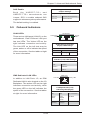
Hot Swap Fan Warning
Warning!
The fans might still be turning when you remove the fan assembly from the chassis.
Keep fingers, screwdrivers, and other objects away from the openings in the fan
assembly's housing.
ファン・ホットスワップの警告
シャーシから冷却ファン装置を取り外した際、
ファンがまだ回転している可能性があり
ます。ファンの開口部に、指、
ドライバー、およびその他のものを近づけないで下さい。
警告
4-16
Chapter 4: Warning Statements for AC Systems
当您从机架移除风扇装置,风扇可能仍在转动。小心不要将手指、螺丝起子和其他
物品太靠近风扇
警告
當您從機架移除風扇裝置,風扇可能仍在轉動。小心不要將手指、螺絲起子和其他
物品太靠近風扇。
Warnung
Die Lüfter drehen sich u. U. noch, wenn die Lüfterbaugruppe aus dem Chassis
genommen wird. Halten Sie Finger, Schraubendreher und andere Gegenstände
von den Öffnungen des Lüftergehäuses entfernt.
¡Advertencia!
Los ventiladores podran dar vuelta cuando usted quite ell montaje del ventilador
del chasis. Mandtenga los dedos, los destornilladores y todos los objetos lejos de
las aberturas del ventilador
Attention
Il est possible que les ventilateurs soient toujours en rotation lorsque vous retirerez
le bloc ventilateur du châssis. Prenez garde à ce que doigts, tournevis et autres
objets soient éloignés du logement du bloc ventilateur.
!אזהרה
יש. יתכן והמאווררים עדיין עובדים,כאשר מסירים את חלקי המאוורר מהמארז
להרחיק למרחק בטוח את האצבעות וכלי עבודה שונים מהפתחים בתוך המאוורר
ﻣﻦ ﺍﻟﻤﻤﻜﻦ ﺃﻥ ﺍﻟﻤﺮﺍﻭﺡ ﻻ ﺗﺰﺍﻝ ﺗﺪﻭﺭﻋﻨﺪ ﺇﺯﺍﻟﺔ ﻛﺘﻠﺔ ﺍﻟﻤﺮﻭﺣﺔ ﻣﻦ ﺍﻟﻬﻴﻜﻞ ﻳﺠﺐ ﺇﺑﻘﺎء
ﺍﻷﺻﺎﺑﻊ ﻭﻣﻔﻜﺎﺕ ﺍﻟﺒﺮﺍﻏﻲ
.ﻭﻏﻴﺮﻫﺎ ﻣﻦ ﺍﻷﺷﻴﺎء ﺑﻌﻴﺪﺍ ﻋﻦ ﺍﻟﻔﺘﺤﺎﺕ ﻓﻲ ﻛﺘﻠﺔ ﺍﻟﻤﺮﻭﺣﺔ
경고!
섀시로부터 팬 조립품을 제거할 때 팬은 여전히 회전하고 있을 수 있습니다. 팬
조림품 외관의 열려있는 부분들로부터 손가락 및 스크류드라이버, 다른 물체들이
가까이 하지 않도록 배치해 주십시오.
4-17
FatTwin F627G2-FT+/FTPT+/F73+/F73PT+ USER'S MANUAL
Waarschuwing
Het is mogelijk dat de ventilator nog draait tijdens het verwijderen van het
ventilatorsamenstel uit het chassis. Houd uw vingers, schroevendraaiers en
eventuele andere voorwerpen uit de buurt van de openingen in de ventilatorbehuizing.
Power Cable and AC Adapter
Warning!
When installing the product, use the provided or designated connection cables,
power cables and AC adaptors. Using any other cables and adaptors could cause
a malfunction or a fire. Electrical Appliance and Material Safety Law prohibits the
use of UL or CSA -certified cables (that have UL/CSA shown on the code) for any
other electrical devices than products designated by Supermicro only.
電源コードとACアダプター
製品を設置する場合、提供または指定された接続ケーブル、電源コードとACアダプター
を使用下さい。他のケーブルやアダプタを使用すると故障や火災の原因になることがあ
ります。電気用品安全法は、ULまたはCSA認定のケーブル(UL/CSEマークがコードに表
記)を Supermicroが指定する製品以外に使用することを禁止しています。
警告
安装此产品时,请使用本身提供的或指定的连接线,电源线和电源适配器.使用其它线
材或适配器可能会引起故障或火灾。除了Supermicro所指定的产品,电气用品和材
料安全法律规定禁止使用未经UL或CSA认证的线材。(线材上会显示UL/CSA符号)。
警告
安裝此產品時,請使用本身提供的或指定的連接線,電源線和電源適配器.使用其它線
材或適配器可能會引起故障或火災。除了Supermicro所指定的產品,電氣用品和材
料安全法律規定禁止使用未經UL或CSA認證的線材。(線材上會顯示UL/CSA符號)。
Warnung
Bei der Installation des Produkts, die zur Verfügung gestellten oder benannt
Anschlusskabel, Stromkabel und Netzteile. Verwendung anderer Kabel und Adapter
kann zu einer Fehlfunktion oder ein Brand entstehen. Elektrische Geräte und
Material Safety Law verbietet die Verwendung von UL-oder CSA-zertifizierte Kabel,
UL oder CSA auf der Code für alle anderen elektrischen Geräte als Produkte von
Supermicro nur bezeichnet gezeigt haben.
4-18
Chapter 4: Warning Statements for AC Systems
¡Advertencia!
Al instalar el producto, utilice los cables de conexión previstos o designados, los
cables y adaptadores de CA. La utilización de otros cables y adaptadores podría
ocasionar un mal funcionamiento o un incendio. Aparatos Eléctricos y la Ley de
Seguridad del Material prohíbe el uso de UL o CSA cables certificados que tienen
UL o CSA se muestra en el código de otros dispositivos eléctricos que los productos
designados por Supermicro solamente.
Attention
Lors de l'installation du produit, utilisez les bables de connection fournis ou désigné.
L'utilisation d'autres cables et adaptateurs peut provoquer un dysfonctionnement
ou un incendie. Appareils électroménagers et de loi sur la sécurité Matériel interdit
l'utilisation de UL ou CSA câbles certifiés qui ont UL ou CSA indiqué sur le code
pour tous les autres appareils électriques que les produits désignés par Supermicro
seulement.
AC
חשמליים ומתאמי
!אזהרה
אשרAC ספקים ומתאמים, יש להשתמש בכבלים,כאשר מתקינים את המוצר
שימוש בכל כבל או מתאם אחר יכול לגרום לתקלה או.נועדו וסופקו לשם כך
קיים איסור, על פי חוקי שימוש במכשירי חשמל וחוקי בטיחות.קצר חשמלי
)כשאר מופיע עליהם קוד שלCSA - או בUL -להשתמש בכבלים המוסמכים ב
.( עבור כל מוצר חשמלי אחר שלא צוין על ידי סופרקמיקרו בלבדUL/CSA
ﻭﺍﻟﻜﺎﺑﻼﺕ ﺍﻟﻜﻬﺮﺑﺎﺋﻴﺔ،ﻋﻨﺪ ﺗﺮﻛﻴﺐ ﺍﻟﺠﻬﺎﺯ ﻳﺠﺐ ﺍﺳﺘﺨﺪﺍﻡ ﻛﺎﺑﻼﺕ ﺍﻟﺘﻮﺻﻴﻞ
ﻭﻣﺤﻮﻻﺕ ﺍﻟﺘﻴﺎﺭ ﺍﻟﻤﺘﺮﺩﺩ
. ﺃﻥ ﺍﺳﺘﺨﺪﺍﻡ ﺃﻱ ﻛﺎﺑﻼﺕ ﻭﻣﺤﻮﻻﺕ ﺃﺧﺮﻯ ﻳﺘﺴﺒﺐ ﻓﻲ ﺣﺪﻭﺙ ﻋﻄﻞ ﺃﻭ ﺣﺮﻳﻖ. ﺍﻟﺘﻲ
ﺗﻢ ﺗﻮﻓﻴﺮﻫﺎ ﻟﻚ ﻣﻊ ﺍﻟﻤﻨﺘﺞ
UL ﺃﻭCSA ﺍﻷﺟﻬﺰﺓ ﺍﻟﻜﻬﺮﺑﺎﺋﻴﺔ ﻭﻣﻮﺍﺩ ﻗﺎﻧﻮﻥ ﺍﻟﺴﻼﻣﺔ ﻳﺤﻈﺮ ﺍﺳﺘﺨﺪﺍﻡ ﺍﻟﻜﺎﺑﻼﺕ
ﻣﻌﺘﻤﺪﺓ ﻣﻦ ﻗﺒﻞ
Supermicro ﻷﻱ ﺃﺟﻬﺰﺓ ﻛﻬﺮﺑﺎﺋﻴﺔ ﺃﺧﺮﻯ ﻏﻴﺮ ﺍﻟﻤﻨﺘﺠﺎﺕ ﺍﻟﻤﻌﻴﻨﺔ ﻣﻦ ﻗﺒﻞ
(UL/CSA )ﺍﻟﺘﻲ ﺗﺤﻤﻞ ﻋﻼﻣﺔ
경고!
제품을 설치할 때에는 제공되거나 지정된 연결케이블과 전원케이블, AC어댑터를
사용해야 합니다. 그 밖의 다른 케이블들이나 어댑터들은 고장 또는 화재의 원인이
될 수 있습니다. 전기용품안전법 (Electrical Appliance and Material Safety
Law)은 슈퍼마이크로에서 지정한 제품들 외에는 그 밖의 다른 전기 장치들을
위한 UL또는 CSA에서 인증한 케이블(전선 위에 UL/CSA가 표시)들의 사용을
금지합니다.
4-19
FatTwin F627G2-FT+/FTPT+/F73+/F73PT+ USER'S MANUAL
Waarschuwing
Bij het installeren van het product, gebruik de meegeleverde of aangewezen kabels,
stroomkabels en adapters. Het gebruik van andere kabels en adapters kan leiden
tot een storing of een brand. Elektrisch apparaat en veiligheidsinformatiebladen wet
verbiedt het gebruik van UL of CSA gecertificeerde kabels die UL of CSA die op
de code voor andere elektrische apparaten dan de producten die door Supermicro
alleen.
4-20
Chapter 5: Advanced Motherboard Setup
Chapter 5
Advanced Motherboard Setup
This chapter covers the steps required to install the X9DRFF-iG+/iTG+/7G+/7TG+
motherboard into the chassis, connect the data and power cables and install add-on
cards. All motherboard jumpers and connections are also described. A layout and
quick reference chart are included in this chapter for your reference. Remember to
completely close the chassis when you have finished working with the motherboard
to better cool and protect the system.
5-1
Handling the Motherboard
Electrostatic Discharge (ESD) can damage electronic components. To prevent
damage to any printed circuit boards (PCBs), it is important to handle them very
carefully (see previous chapter). To prevent the motherboard from bending, keep
one hand under the center of the board to support it when handling. The following
measures are generally sufficient to protect your equipment from electric static
discharge.
Precautions
•
•
•
•
•
•
Use a grounded wrist strap designed to prevent Electrostatic Discharge (ESD).
Touch a grounded metal object before removing any board from its antistatic bag.
Handle a board by its edges only; do not touch its components, peripheral chips,
memory modules or gold contacts.
When handling chips or modules, avoid touching their pins.
Put the motherboard, add-on cards and peripherals back into their antistatic
bags when not in use.
For grounding purposes, make sure your computer chassis provides excellent
conductivity between the power supply, the case, the mounting fasteners and
the motherboard.
Unpacking
The motherboard is shipped in antistatic packaging to avoid electrical static
discharge. When unpacking the board, make sure the person handling it is static
protected.
5-1
FatTwin F627G2-FT+/FTPT+/F73+/F73PT+ USER'S MANUAL
5-2
Connecting Cables
The FatTwin F627G2-FT+/FTPT+/F73+/F73PT+ server needs to have both power
and data cables connected to the X9DRFF-iG+/iTG+/7G+/7TG+ serverboard.
Connecting Power Cables
Four (4) 40-cm and 45-cm 18AWG 8-pin male to two 4-pin male power cables (part
number CBL-0460L-02) are used to power SATA drives connecting to the SATA
backplane and the serverboard for SATA drive power.
Connecting Data Cables
The cables used to transfer data from the peripheral devices have been carefully
routed in preconfigured systems to prevent them from blocking the flow of cooling
air that moves through the system from front to back. If you need to disconnect
any of these cables, you should take care to reroute them as they were originally
after reconnecting them (make sure the red wires connect to the pin 1 locations). If
you are configuring the system, keep the airflow in mind when routing the cables.
The FatTwin F627G2-FT+/FTPT+/F73+/F73PT+ system uses the following data
cables:
•
•
Twenty-Four (24) 21-cm 30AWG SATA S-S cables (CBL-0473L)
Eight (8) 27-cm 8-pin to 8-pin ribbon SGPIO cables with tube (CBL-0157L-02)
to connect to the system for data.
5-2
Chapter 5: Advanced Motherboard Setup
5-3
Control Panel Connectors and I/O Ports
The rear I/O ports are color coded in conformance with the PC 99 specification. See
Figure 5-1 below for the colors and locations of the various I/O ports.
Figure 5-1. Front I/O Ports
1
2
3
4
5
6
Back Panel I/O Port Locations and Definitions
1.
Back Panel USB Port 1
2.
Back Panel USB Port 2
3.
IPMI LAN
4.
Gigabit LAN 1 (for F627G2-FT+/F627G2-F73+) or 10-Gigabit LAN 1 (for
F627G2-FTPT+/F627G2-F73PT+)
5.
Gigabit LAN 2 (for F627G2-FT+/F627G2-F73+) or 10-Gigabit LAN 1 (for
F627G2-FTPT+/F627G2-F73PT+)
6.
VGA Port
7
Power Switch LED
5-3
7
FatTwin F627G2-FT+/FTPT+/F73+/F73PT+ USER'S MANUAL
5-4
Processor and Heatsink Installation
Warning! When handling the processor package, avoid placing direct pressure on
the label area.
Warning! If you buy a CPU separately, make sure that you use an Intel-certified multidirectional heatsink only.
Note: Always connect the power cord last, and always remove it before adding,
removing or changing any hardware components. Make sure that you install the
processor into the CPU socket before you install the CPU heatsink.
Note: Make sure to install the system board into the chassis before you install the
CPU heatsink.
Note: When receiving a server board without a processor pre-installed, make sure that
the plastic CPU socket cap is in place and none of the socket pins are bent; otherwise,
contact your retailer immediately.
Note: Refer to the Supermicro website for updates on CPU support.
Note: When one CPU is installed, be sure to installed on CPU Socket 1 first.
Installing the Socket R LGA 2011 Processor
1. There are two load levers on the LGA2011 socket. To open the socket cover,
first press and release the load lever labeled 'Open 1st'.
2. Press the second load lever labeled 'Close 1st' to release the load plate that
covers the CPU socket from its locking position.
WA
R
WA
RN
IN
G!
OP
EN
OP
EN
1st
NI
NG
!
1st
Press down on Load Lever
labeled 'Open 1st'.
3. With the lever labeled 'Close 1st' fully retracted, gently push down on
the 'Open 1st' lever to open the load plate. Lift the load plate to open it
completely.
5-4
Chapter 5: Advanced Motherboard Setup
Press down on Load the Lever
labeled 'Close 1st'
WA
R
OP
EN
NI
Pull lever away
from the socket
WA
RN
IN
G!
NG
!
OP
EN
1st
1st
Gently push down to pop the
load plate open.
WA
R
OP
EN
NI
NG
!
1st
WA
R
NI
NG
!
4. Using your thumb and the index finger, remove the 'WARNING' plastic cap
from the socket.
WA
R
NIN
G!
5-5
FatTwin F627G2-FT+/FTPT+/F73+/F73PT+ USER'S MANUAL
5. Use your thumb and index finger to hold the CPU on its edges. Align the CPU
keys, which are semi-circle cutouts, against the socket keys.
Socket Keys
CPU Keys
6. Once they are aligned, carefully lower the CPU straight down into the socket.
(Do not drop the CPU on the socket. Do not move the CPU horizontally or
vertically. Do not rub the CPU against the surface or against any pins of the
socket to avoid damaging the CPU or the socket.)
Caution: You can only install the CPU inside the socket in one direction. Make sure
that it is properly inserted into the CPU socket before closing the load plate. If it doesn't
close properly, do not force it as it may damage your CPU. Instead, open the load
plate again and double-check that the CPU is aligned properly.
5-6
Chapter 5: Advanced Motherboard Setup
7. With the CPU inside the socket, inspect the four corners of the CPU to make
sure that the CPU is properly installed.
8. Close the load plate with the CPU inside the socket. Lock the lever labeled
'Close 1st' first, then lock the lever labeled 'Open 1st' second. Use your
thumb to gently push the load levers down to the lever locks.
9. Repeat steps to install a CPU to CPU Socket #2 if needed.
Gently close the
load plate.
Push down and lock the
level labeled 'Close 1st'.
OP
EN
1st
Lever Lock
Push down and lock
the lever labeled
'Open 1st'
OP
OP
EN
1st
EN
1st
Lever Lock
5-7
FatTwin F627G2-FT+/FTPT+/F73+/F73PT+ USER'S MANUAL
Installing a CPU Heatsink
1. Place the heatsink on top of the CPU so that the four mounting holes are
aligned with those on the retention mechanism.
2. Screw in two diagonal screws (i.e. the #1 and the #2 screws) until just snug
(do not over-tighten the screws, which may damage the CPU.)
3. Finish the installation by fully tightening all four screws.
Removing the Heatsink
1. Unplug the power cord from the power supply.
2. Unscrew and remove the heatsink screws in the sequence shown in the
picture below.
3. Hold the heatsink and gently wiggle it to loosen it from the CPU. (Do not use
excessive force when doing this!)
4. Once the heatsink is loosened, remove it from the CPU.
5. Clean the surface of the CPU and the heatsink to get rid of the old thermal
grease. Reapply the proper amount of thermal grease before you re-install
the heatsink.
Warning: We do not recommend removing the CPU or the heatsink. If you do need
to remove the heatsink, please follow the instructions below to prevent damage to the
CPU or other components.
5-8
Chapter 5: Advanced Motherboard Setup
5-5
Installing Memory
Caution: exercise extreme care when installing or removing DIMM modules to prevent
any possible damage.
Installing Memory
1. Insert the desired number of DIMMs into the memory slots, starting with
P1-DIMM #1A. (For best performance, please use the memory modules of the
same type and speed in the same bank.)
2. Push the release tabs outwards on both ends of the DIMM slot to unlock it.
3. Align the key of the DIMM module with the receptive point on the memory
slot.
4. Align the notches on both ends of the module against the receptive points on
the ends of the slot.
5. Use two thumbs together to press the notches on both ends of the module
straight down into the slot until the module snaps into place.
6. Press the release tabs to the locking positions to secure the DIMM module
into the slot.
Reverse the steps above to remove the DIMM modules from the motherboard.
Note: 1 GB, 2 GB, 4 GB, 8 GB, 16 GB or 32 GB size memory modules are
supported. It is highly recommended that you remove the power cord from the
system before installing or changing memory modules. Please refer to our web site
for memory that has been tested on the X9DRFF-iG+/iTG+/7G+/7TG+ serverboard.
Figure 5-2. Installing DIMM into Slot
To Install: Insert
module vertically and
press down until it
snaps into place.
Pay attention to the
alignment notch at
the bottom.
Notch
To Remove: Use
your thumbs to gently Release Tab
push the release tabs
near both ends of the
module. This should
release it from the
slot.
Notch
Front View
Note: Notch should align with
the receptive key point on
the slot.
Release Tab
Top View of DDR3 Slot
5-9
FatTwin F627G2-FT+/FTPT+/F73+/F73PT+ USER'S MANUAL
Removing Memory Modules
Press both notches on the ends of the DIMM module to unlock it. Once the DIMM
module is loosened, remove it from the memory slot.
Memory Support
The X9DRFF-iG+/iTG+/7G+/7TG+ motherboard supports up to 512 GB of 240-pin
Registered (RDIMM)/Load Reduced (LRDIMM) ECC or up to 128 GB of Unbuffered
(UDIMM) ECC/Non-ECC DDR3-1600/1333/1066/800 MHz speed 4-channel
memory in sixteen (16) DIMM slots.
Note: For the latest CPU/memory updates, please refer to our website at
http://www.supermicro.com/products/motherboard.
Processors and their Corresponding Memory Modules
CPU#
Corresponding DIMM Modules
CPU 1
P1DIMMA1
P1DIMMB1
P1DIMMC1
P1DIMMD1
P1DIMMA2
P1DIMMB2
P1DIMMC2
P1DIMMD2
CPU2
P2DIMME1
P2DIMMF1
P2DIMMG1
P2DIMMH1
P2DIMME2
P2DIMM F2
P2DIMMG2
P2DIMMH2
Processor and Memory Module Population for Optimal Performance
Number of
CPUs+DIMMs
CPU and Memory Population Configuration Table
(For memory to work properly, please follow the tables below.)
1 CPU &
2 DIMMs
CPU1
P1-DIMMA1/P1-DIMMB1
1 CPU &
4 DIMMs
CPU1
P1-DIMMA1/P1-DIMMB1, P1-DIMMC1/P1-DIMMD1
1 CPU &
5~8 DIMMs
CPU1
P1-DIMMA1/P1-DIMMB1, P1-DIMMC1/P1-DIMMD1 + Any memory pairs in P1-DIMMA2/
P1-DIMMB2/P1-DIMMC2/P1-DIMMD2 slots
2 CPUs &
4 DIMMs
CPU1 + CPU2
P1-DIMMA1/P1-DIMMB1, P2-DIMME1/P2-DIMMF1
2 CPUs &
6 DIMMs
CPU1 + CPU2
P1-DIMMA1/P1-DIMMB1/P1-DIMMC1/P1-DIMMD1, P2-DIMME1/P2-DIMMF1
2 CPUs &
8 DIMMs
CPU1 + CPU2
P1-DIMMA1/P1-DIMMB1/P1-DIMMC1/P1-DIMMD1, P2-DIMME1/P2-DIMMF1/P2DIMMG1/P2-DIMMH1
2 CPUs &
10~16 DIMMs
CPU1/CPU2
P1-DIMMA1/P1-DIMMB1/P1-DIMMC1/P1-DIMMD1, P2-DIMME1/P2-DIMMF1/P2DIMMG1/P2-DIMMH1 + Any memory pairs in P1, P2 DIMM slots
2 CPUs &
16 DIMMs
CPU1/CPU2
P1-DIMMA1/P1-DIMMB1/P1-DIMMC1/P1-DIMMD1, P2-DIMME1/P2-DIMMF1/P2DIMMG1/P2-DIMMH1,P1-DIMMA2/P1-DIMMB2/P1-DIMMC2/P1-DIMMD2, P2-DIMME2/
P2-DIMMF2/P2-DIMMG2/P2-DIMMH2
Notes: 1866 MHz memory speed is dependent on Intel E5-2600v2 CPUs. For Intel
E5-2600(v2) processor support, BIOS version 3.0 or above is required.
5-10
Chapter 5: Advanced Motherboard Setup
Populating UDIMM (ECC/Non-ECC) Memory Modules
Intel E5-2600(v2) Series Processor UDIMM Memory Support
Ranks
Per
DIMM
& Data
Width
Memory
Capacity
Per DIMM
(See the Note
below)
Speed (MT/s) and Voltage Validated by Slot per Channel (SPC)
and DIMM Per Channel (DPC)
2 Slots Per Channel
1DPC
3 Slots Per Channel
2DPC
1DPC
2DPC
1.35V
1.5V
1.35V
1.5V
1.35V
1.5V
1.35V
1.5v
SRx8
NonECC
1GB
2GB
4GB
NA
1066,
1333,
1600,
1866
NA
1066,
1333,
1600
N/A
1066,
1333,
1600,
1866
N/A
1066,
1333,
1600
DRx8
NonECC
2GB
4GB
8GB
NA
1066,
1333,
1600,
1866
NA
1066,
1333,
1600
N/A
1066,
1333,
1600,
1866
N/A
1066,
1333,
1600
SRx16
NonECC
512
MB
1GB
2GB
NA
1066,
1333,
1600,
1866
NA
1066,
1333,
1600
N/A
1066,
1333,
1600,
1866
N/A
1066,
1333,
1600
SRx8
ECC
1GB
2GB
4GB
1066,
1333
1066,
1333,
1600,
1866
1066,
1333
1066,
1333,
1600
1066,
1333
1066,
1333,
1600,
1866
1066,
1333
1066,
1333,
1600
DRx8
ECC
2GB
4GB
8GB
1066,
1333
1066,
1333,
1600,
1866
1066,
1333
1066,
1333,
1600
1066,
1333
1066,
1333,
1600,
1866
1066,
1333
1066,
1333,
1600
Note: For detailed information on memory support and updates, please refer to the SMC Recommended Memory
List posted on our website at http://www.supermicro.com/support/resources/mem.cfm.
5-11
FatTwin F627G2-FT+/FTPT+/F73+/F73PT+ USER'S MANUAL
Populating UDIMM (ECC/Non-ECC) Memory Modules
Intel E5-2600 Series Processor UDIMM Memory Support
Ranks
Per
DIMM
& Data
Width
Memory
Capacity
Per DIMM
(See the Note
below)
Speed (MT/s) and Voltage Validated by Slot per Channel (SPC)
and DIMM Per Channel (DPC)
2 Slots Per Channel
1DPC
3 Slots Per Channel
2DPC
1DPC
2DPC
1.35V
1.5V
1.35V
1.5V
1.35V
1.5V
1.35V
1.5v
SRx8
NonECC
1GB
2GB
4GB
NA
1066,
1333
NA
1066,
1333
N/A
1066,
1333,
N/A
1066,
1333
DRx8
NonECC
2GB
4GB
8GB
NA
1066,
1333
NA
1066,
1333
N/A
1066,
1333,
N/A
1066,
1333
SRx16
NonECC
512
MB
1GB
2GB
NA
1066,
1333
NA
1066,
1333
N/A
1066,
1333
N/A
1066,
1333
SRx8
ECC
1GB
2GB
4GB
1066,
1333
1066,
1333
1066
1066,
1333
1066
1066,
1333,
1066,
1333
1066,
1333
DRx8
ECC
2GB
4GB
8GB
1066,
1333
1066,
1333
1066
1066,
1333
1066
1066,
1333,
1066,
1333
Note: For detailed information on memory support and updates, please refer to the SMC Recommended
Memory List posted on our website at http://www.supermicro.com/support/resources/mem.cfm..
5-12
1066,
1333
Chapter 5: Advanced Motherboard Setup
Populating RDIMM (ECC) Memory Modules
Intel E5-2600(v2) Series Processor RDIMM Memory Support
Ranks
Per
DIMM
& Data
Width
Memory
Capacity
Per DIMM
(in GB)
Speed (MT/s) and Voltage Validated by Slot per Channel (SPC)
and DIMM Per Channel (DPC)
2 Slots Per Channel
1DPC
(See the
Note
Below)
2DPC
3 Slots Per Channel
1 DPC
2DPC
3DPC
1.35V
1.5V
1.35V
1.5V
1.35V
1.5V
1.35V
1.5V
1.35V
1.5v
SRx8
1
2
4
1066,
1333
1066,
1333,
1600,
1866
1066,
1333
1066,
1333,
1600
1066,
1333
1066,
1333,
1600,
1866
1066,
1333
1066,
1333,
1600
800
800,
1066
DRx8
2
4
8
1066,
1333
1066,
1333,
1600,
1866
1066,
1333
1066,
1333,
1600
1066,
1333
1066,
1333,
1600,
1866
1066,
1333
1066,
1333,
1600
800
800,
1066
SRx4
2
4
8
1066,
1333
1066,
1333,
1600,
1866
1066,
1333
1066,
1333,
1600
1066,
1333
1066,
1333,
1600,
1866
1066,
1333
1066,
1333,
1600
800
800,
1066
DRx4
4
8
16
1066,
1333
1066,
1333,
1600,
1866
1066,
1333
1066,
1333,
1600
1066,
1333
1066,
1333,
1600,
1866
1066,
1333
1066,
1333,
1600
800
800,
1066
QRx4
8
16
32
800
800
1066
800
800
800
800,
1066
800
800
N/A
N/A
QRx8
4
8
16
800
800
1066
800
800
800
800,
1066
800
800
N/A
N/A
Note: For detailed information on memory support and updates, please refer to the SMC Recommended
Memory List posted on our website at http://www.supermicro.com/support/resources/mem.cfm.
5-13
FatTwin F627G2-FT+/FTPT+/F73+/F73PT+ USER'S MANUAL
Populating RDIMM (ECC) Memory Modules
Intel E5-2600 Series Processor RDIMM Memory Support
Ranks
Per
DIMM
& Data
Width
Memory
Capacity
Per DIMM
(in GB)
Speed (MT/s) and Voltage Validated by Slot per Channel (SPC)
and DIMM Per Channel (DPC)
2 Slots Per Channel
1DPC
(See the
Note
Below)
2DPC
3 Slots Per Channel
1 DPC
2DPC
3DPC
1.35V
1.5V
1.35V
1.5V
1.35V
1.5V
1.35V
1.5V
1.35V
1.5v
SRx8
1
2
4
1066,
1333
1066,
1333,
1600
1066,
1333
1066,
1333,
1600
1066,
1333
1066,
1333,
1600
1066,
1333
1066,
1333,
1600
N/A
800,
1066
DRx8
2
4
8
1066,
1333
1066,
1333,
1600
1066,
1333
1066,
1333,
1600
1066,
1333
1066,
1333,
1600
1066,
1333
1066,
1333,
1600
N/A
800,
1066
SRx4
2
4
8
1066,
1333
1066,
1333,
1600
1066,
1333
1066,
1333,
1600
1066,
1333
1066,
1333,
1600
1066,
1333
1066,
1333,
1600
N/A
800,
1066
DRx4
4
8
16
1066,
1333
1066,
1333,
1600
1066,
1333
1066,
1333,
1600
1066,
1333
1066,
1333,
1600
1066,
1333
1066,
1333,
1600
N/A
800,
1066
QRx4
8
16
32
800
1066
800
800
800
1066
800
800
N/A
N/A
QRx8
4
8
16
800
1066
800
800
800
1066
800
800
N/A
N/A
Note: For detailed information on memory support and updates, please refer to the SMC Recommended
Memory List posted on our website at http://www.supermicro.com/support/resources/mem.cfm..
5-14
Chapter 5: Advanced Motherboard Setup
Populating LRDIMM (ECC) Memory Modules
Intel E5-2600(v2) Series Processor LRDIMM Memory Support
Ranks
Per
DIMM
& Data
Width
Memory
Capacity
Per DIMM
(in GB)
Speed (MT/s) and Voltage Validated by Slot per Channel (SPC) and
DIMM Per Channel (DPC)
2 Slots Per Channel
1DPC
(See the
Note
Below)
2DPC
3 Slots Per Channel
1DPC
2DPC
3DPC
1.35V
1.5V
1.35V
1.5V
1.35V
1.5V
1.35V
1.5V
1.35V
1.5V
QRx4
(DDP)
16
32
1066,
1333,
1600
1066,
1333,
1600,
1866
1066,
1333,
1600
1066,
1333,
1600
1066,
1333,
1600
1066,
1333,
1600,
1866
1066,
1333,
1600
1066,
1333,
1600
1066
1066
8Rx4
(QDP)
32
64
1066
1066
1066
1066
1066
1066
1066
1066
1066
1066
Note: For detailed information on memory support and updates, please refer to the SMC Recommended
Memory List posted on our website at http://www.supermicro.com/support/resources/mem.cfm.
Intel E5-2600 Series Processor LRDIMM Memory Support
Ranks
Per
DIMM
& Data
Width
Memory
Capacity
Per DIMM
(in GB)
Speed (MT/s) and Voltage Validated by Slot per Channel (SPC) and
DIMM Per Channel (DPC)
2 Slots Per Channel
1DPC
(See the
Note
Below)
2DPC
3 Slots Per Channel
1DPC
2DPC
3DPC
1.35V
1.5V
1.35V
1.5V
1.35V
1.5V
1.35V
1.5V
1.35V
1.5V
QRx4
(DDP)
16
32
1066
1066,
1333
1066
1066,
1333
1066
1066,
1333
1066
1066,
1333
1066
1066
QRx8
(QDP)
8
16
1066
1066,
1333
1066
1066,
1333
1066
1066
1066
1066
1066
1066
Note: For detailed information on memory support and updates, please refer to the SMC Recommended
Memory List posted on our website at http://www.supermicro.com/support/resources/mem.cfm.
Other Important Notes and Restrictions
•
•
For the memory modules to work properly, please install DIMM modules of the
same type, same speed and same operating frequency on the motherboard.
Mixing of RDIMMs, UDIMMs or LRDIMMs is not allowed. Do not install both ECC
and Non-ECC memory modules on the same motherboard.
Using DDR3 DIMMs with different operating frequencies is not allowed. All
channels in a system will run at the lowest common frequency.
5-15
FatTwin F627G2-FT+/FTPT+/F73+/F73PT+ USER'S MANUAL
Serverboard Details
5-6
Figure 5-3. X9DRFF-iG+/iTG+/7G+/7TG+ Serverboard Layout
JSD1
I-SATA5
I-SATA4
I-SATA3
I-SATA2
L-SAS6
L-SAS4
L-SAS2
L-SAS0
I-SATA0 I-SATA1
CLOSE 1st
6-SGPIO2
6-SGPIO1
T-SGPIO2
T-SGPIO1
P1-DIMMA1
P1-DIMMA2
P1-DIMMB1
HDD_PWR2
P1-DIMMD2
P1-DIMMD1
L-SAS7
L-SAS5
L-SAS3
L-SAS1
P2-DIMME2
P2-DIMMF2
P2-DIMMF1
P2-DIMME1
SXB1:CPU2 PCI-E X32
PROPRIENTAR SLOT
P2-DIMMH1
P2-DIMMH2
P2-DIMMG2
P2-DIMMG1
FAN5
FAN6
FAN3
FAN4
FAN2
FAN1
HDD
JPW1 PWR1
FAN8
5-16
P1-DIMMB2
P1-DIMMC1
P1-DIMMC2
CPU1
JPS1
X9DRFF-iG+
MAC CODE
PCH SLOT4 PCIE-E 2.0X4
HDD_ACT_LED1
JPME2
USB0
JPG1
JPB1
CPLD1
LSI SAS
CTRL
Rev. 1.01
JP6
JBR1
JIPMB1 JPI2C1
FAN7
LEDS2
CPU1 SLOT3 PCI-E 3.0X8
BMC_HB_LED1
JBT1
JBAT1
CPU1 SLOT2 PCI-E 3.0X8
CPU1 SLOT1 PCI-E X16 PROPRIETARY SLOT
JP7
Rear_FAN
PS_ON_N
USB1
PWR_SW1
UID_SW1
UID_LED1
FAILURE_LED1
BMC
IPMI_ LAN
JPL1
CLOSE 1st
JPW2
SAS CODE
BIOS
1
CPU2
JPW3
MEGERAC LICENSE
Intel PCH
IPMI CODE
JWD1
JI2C2
JI2C1
USB2
LAN1
LAN2
Intel LAN
CTRL
JPME1
VGA1
OPEN 1st
OPEN 1st
Chapter 5: Advanced Motherboard Setup
Notes:
1. For the latest CPU/Memory updates, please refer to our website at http://
www.supermicro.com/products/motherboard/ for details.
2. Use only the correct type of onboard CMOS battery as specified by the
manufacturer. Do not install the onboard battery upside down to avoid
possible explosion.
3. Both the X9DRFF-iTG+ and X9DRFF-7TG+ serverboards include 10-GB
Ethernet ports.
4. Jumpers not indicated are for test purposes only.
5. All graphics shown in this manual were based upon the latest PCB Revision
available at the time of publishing of the manual. The motherboard you've
received may or may not look exactly the same as the graphics shown in this
manual.
5-17
FatTwin F627G2-FT+/FTPT+/F73+/F73PT+ USER'S MANUAL
X9DRFF-7TG+/X9DRFF-7G+ Quick Reference
Jumper
Description
Default Setting
JBT1
Clear CMOS
See Section 5-9
JI2C1/JI2C2
SMB to PCI-E Slots
Open (Disabled)
JPB1
BMC Enable
Pins 1-2 (Enabled)
JPG1
VGA Enable
Pins 1-2 (Enabled)
JPL1
LAN1/LAN2 Enable
Pins 1-2 (Enabled)
JPS1
SAS Enable
Pins 1-2 (Enabled)
JWD1
Watch Dog Timer Enable
Pins 1-2 (Reset)
Connector
Description
FAN1-FAN8, Rear_FAN1
CPU/System/Cooling Fan Headers
HDD_PWR1/HDD_PWR2
8-pin Power Supply Connectors for HDD Device Use
I-SATA 0/1
SATA 3.0 Connectors 0/1 from Intel AHCI
I-SATA 2-5
SATA 2.0 Connectors 2/3/4/5 from Intel AHCI
JIPMB1
4-pin External BMC I2C Header (for IPMI Card)
JPI2C1
Power Supply SMBbus I2C Header
JPW1/JPW2
8-pin Power Connectors
JPW3
4-pin Power Connector
JSD1
SATA Device Power Connector
JTPM1
TPM (Trusted Platform Module)/Port 80 Connector
(J) USB2
Internal USB 2 Port
L-SAS 0-7
SAS Ports 0-7 from LSI 2308 SAS Controller
6-SGPIO 1/2
Serial Link General Purpose I/O Headers for SAS
T-SGPIO 1/2
Serial Link General Purpose I/O Headers for SATA
PWR_SW1
Power Switch (Button)
UID_SW1
UID (Unit Identifier) Switch (SW1)
USB0/USB1
Front Panel USB 0/ USB1 Ports
LED
Description
State: Status
BMC_HB_LED1
BMC Heartbeat LED
Blinking Green: BMC Normal
HDD_ACT LED1
HDD Activity LED
Blinking Green: HDD Active
Failure_LED1
Failure LED
Blinking On: Power Failure; Blinking:
Fan Failure
LEDS2
SAS Heartbeat LED
On (Green): SAS Normal
UID_LED1
UID LED
On (Blue): Unit Identified
5-18
Chapter 5: Advanced Motherboard Setup
5-7
Connector Definitions
ATX Power Connector
Two 8-pin power connectors (JPW1/
12V 8-pin PWR (JPW1/2)
Pin Definitions
JPW2) and a 4-pin power connector
Pins
Definition
(JPW3) are used to provide power to the
1- 4
Ground
serverboard. In addition, two 8-pin power
5-8
+12V
connectors (HDD_PWR1/2) are also
12V 4-pin PWR (JPW3)
Pin Definitions
located onboard to provide power from
the serverboard to the HDD backplane
for HDD device use. Do not use these
connectors for other purposes. All power
connectors mentioned above meet the
SSI EPS 12V specification. See the
tables on the right for pin definitions.
Pins
Definition
1
Ground
2
Ground
3
5V SB
4
PS_ON_N
HDD PWR
Pin Definitions
Pins
Definition
1- 4
Ground
5-6
+12V
7-8
+5V
Universal Serial Bus (USB)
Two Universal Serial Bus ports (USB0,
USB1), located on the I/O front panel,
provide front-accessible USB support.
In addition, a Type A USB connector
(JUSB2), located next to the 4-pin
JIPMB1 connector, also provides frontaccessible USB support.
Video Connection
A Video (VGA) port is located next to the
LAN Port 2 on the I/O backplane. Refer
to the layout below for the location.
5-19
Front Panel USB 0/1
& Type-A USB 2
Pin Definitions
Pin# Definition
1
+5V
2
PO-
3
PO+
4
Ground
5
NA
FatTwin F627G2-FT+/FTPT+/F73+/F73PT+ USER'S MANUAL
Ethernet Ports
Two Ethernet ports (LAN1, LAN2)
are located on the I/O front panel.
These Ethernet ports support 10G
LAN connections on the X9DRFF-iTG+
and X9DRFF-7TG+, or the 1G LAN
connections on the X9DRFF-iG+ and
X9DRFF-7G+.
In addition, an IPMI LAN port is also
located on the front panel. All these
ports accept RJ45 cables. Please refer
to the LED Indicator Section for LAN LED
information.
LAN Ports (LAN1/2)
Pin Definition
Pin# Definition
Pin# Definition
1
P2V5SB
10
2
TD0+
11
Act LED
3
TD0-
12
P3V3SB
4
TD1+
13
Link 100 LED
(Yellow, +3V3SB)
5
TD1-
14
Link 1000 LED
(Yellow, +3V3SB)
6
TD2+
15
Ground
7
TD2-
16
Ground
8
TD3+
17
Ground
9
TD3-
18
Ground
SGND
NC indicates no connection.
Power Button/Unit Identifier Switch
A Unit Identifier switch (SW1) and a
UID LED Indicator are located on the
serverboard. In addition, a power button
(PWR_SW1) is located next to the UID
switch on the front panel. When you press
the UID switch, the UID LED Indicator will
be turned on. Press the UID switch again
to turn off the UID LED. The UID Indicator
provides easy identification of a system
unit that may be in need of service.
Note: UID can also be triggered via IPMI
on the serverboard. For more information
on IPMI, please refer to the IPMI User's
Guide posted on our website @ http://
www.supermicro.com.
5-20
UID Switch (SW1)
Pin Definitions
Pin#
Definition
1
Ground
2
Ground
3
Button In
4
Ground
UID LED (UID_LED1)
Status
Color/State OS
Status
Blue: On
Windows OS
Unit Identified
Blue:
Blinking
Linux OS
Unit Identified
Chapter 5: Advanced Motherboard Setup
Fan Headers
Fan Header
(Fan 1~8, Fan 9)
Pin Definitions
This serverboard has eight 4-pin
(Fan1~Fan8), and one 3-pin (Rear_Fan1)
system/CPU/cooling fan headers on the
serverboard. The 4-pin fan headers are
backward compatible with traditional
3-pin fans. However, fan speed control
is only available on 4-pin fans via IPMI
firmware management. See the table on
the right for pin definitions.
Pin# Definition
1
Ground
2
+12V
3
Tachometer
4
PWR Modulation
(Available for 4-pin fans only)
IPMB
IPMB Header
Pin Definitions
A System Management Bus header for
IPMI 2.0 is located at JIPMB1. Connect
the appropriate cable here to use the
IPMB I2C connection on your system.
Pin#
Definition
1
Data
2
Ground
3
Clock
4
No Connection
SATA DOM Power Connector
DOM PWR (JSD1)
Pin Definitions
A power connector for SATA DOM
(Disk_On_Module) devices is located
at JSD1. Connect an appropriate cable
here to provide power support for your
SATA DOM devices.
Pin# Definition
1
+5V
2
Ground
3
Ground
T-SGPIO 1/2 & 6-SGPIO 1/2 Headers
Four SGPIO (Serial-Link General
Purpose Input/Output) headers
(T-SGPIO 1/2 & 6-SGPIO 1/2) are
located on the motherboard. These
headers support onboard Serial_Link
interface connections.
Note: T-SGPIO 1/2 support onboard
SATA connections. 6-SGPIO 1/2 support
SAS interface on the X9DRFF-7G+ and
X9DRFF-7TG+ serverboards only.
5-21
T-SGPIO 1/2
S-SGPIO 1/2
Pin Definitions
Pin#
Definition
Pin
2
Definition
1
NC
NC
3
Ground
4
Data
5
Load
6
Ground
7
Clock
8
NC
NC indicates no connection.
FatTwin F627G2-FT+/FTPT+/F73+/F73PT+ USER'S MANUAL
Power SMB (I2C) Connector
PWR SMB (JPI2C1)
Pin Definitions
2
Power System Management Bus (I C)
Connector (JPI 2C1) monitors power
supply, fan and system temperatures.
See the table on the right for pin
definitions.
Pin#
Definition
1
Clock
2
Data
3
PWR Fail
4
Ground
5
+3.3V
Power Switch
A power switch (PWR_SW1) is located
next to the VGA port on the motherboard.
Refer to the layout below for the location.
Unit Identification Switch/LED
UID Switch (UID)
Pin Definitions
A Unit Identifier switch (UID) and a UID
LED indicator (UID_LED1) are located
next to the power switch on the front
panel. When the user pushes the UID
switch, the UID LED (UID_LED1) will be
turned on. Push the UID switch again
to turn off the LED indicator. The UID
switch provides easy identification of
a system unit that may be in need of
service. See the tables on the right for
more information.
Pin# Definition
TPM Header/Port 80
A Trusted Platform Module/Port 80
header, located at JTPM1, provides TPM
support and Port 80 connection. Use this
header to enhance system performance
and data security. See the table on the
right for pin definitions.
5-22
1
Ground
2
Ground
3
Button In
4
Ground
TPM/Port 80 Header (JTPM1)
Pin Definitions
Pin# Definition
Pin# Definition
1
LCLK
2
GND
3
LFRAME#
4
<(KEY)>
5
LRESET#
6
+5V (X)
7
LAD 3
8
LAD 2
9
+3.3V
10
LAD1
11
LAD0
12
GND
13
SMB_CLK4
14
SMB_DAT4
15
+3V_DUAL
16
SERIRQ
17
GND
18
CLKRUN# (X)
19
LPCPD#
20
LDRQ# (X)
Chapter 5: Advanced Motherboard Setup
5-8
Jumper Settings
3
2
1
3
2
1
Connector
Pins
Explanation of Jumpers
To modify the operation of the motherboard,
jumpers can be used to choose between
optional settings. Jumpers create shorts
between two pins to change the function
of the connector. Pin 1 is identified with
a square solder pad on the printed circuit
board. See the diagram at right for an
example of jumping pins 1 and 2. Refer
to the motherboard layout page for jumper
locations.
Note: On two-pin jumpers, "Closed" means
the jumper is on and "Open" means the
jumper is off the pins.
Jumper
Setting
JBT1 contact pads
CMOS Clear
JBT1 is used to clear CMOS, which will also clear any passwords. Instead of pins,
this jumper consists of contact pads to prevent accidentally clearing the contents
of CMOS.
To Clear CMOS
1. First power down the system and unplug the power cord(s). It is also
recommended that you remove the onboard battery from the serverboard.
2. With the power disconnected, short the CMOS pads with a metal object such
as a small screwdriver.
3. Remove the screwdriver (or shorting device).
4. Reconnect the power cord(s) and power on the system.
Note 1. For an ATX power supply, you must completely shut down the system,
remove the AC power cord, and then short JBT1 to clear CMOS.
Note 2. Be sure to remove the onboard CMOS Battery before you short JBT1 to
clear CMOS.
Note 3. Clearing CMOS will also clear all passwords.
Note 4: Do not use the PW_ON connector to clear CMOS.
5-23
FatTwin F627G2-FT+/FTPT+/F73+/F73PT+ USER'S MANUAL
GLAN Enable/Disable
JPL1 enables or disables LAN Port1/
LAN Port2 on the motherboard. See the
table on the right for jumper settings.
The default setting is Enabled.
GLAN Enable (JPL1)
Jumper Settings
Jumper Setting
Definition
1-2
Enabled (default)
2-3
Disabled
Watch Dog Enable/Disable
Watch Dog (JWD1) is a system monitor that will reboot the system when a
software application hangs. Close Pins
1-2 to reset the system if an application hangs. Close Pins 2-3 to generate
a non-maskable interrupt signal for the
application that hangs. See the table on
the right for jumper settings. Watch Dog
must also be enabled in the BIOS.
Watch Dog (JWD1)
Jumper Settings
Jumper Setting
Definition
Pins 1-2
Reset (default)
Pins 2-3
NMI
Open
Disabled
VGA Enable
Jumper JPG1 allows the user to enable
onboard VGA support. The default
setting is on Pins 1-2 to enable VGA
support. See the table on the right for
jumper settings.
VGA Enable (JPG1)
Jumper Settings
Jumper Setting
Definition
1-2
Enabled (Default)
2-3
Disabled
BMC Enable
Jumper JPB1 allows you to enable
the embedded BMC (Baseboard
Management) Controller to provide IPMI
2.0 support on the motherboard. See
the table on the right for jumper settings.
I2C Bus to PCI-Exp. Slots
Jumpers JI2C1 and JI2C2 allow you to
connect the System Management Bus
(I2C) to PCI-Express slots. The default
setting is Open to disable the connection.
5-24
BMC Enable (JPB1)
Jumper Settings
Jumper Setting
Definition
Pins 1-2
BMC Enable (Default)
Pins 2-3
Normal
I2C to PCI-Exp (JI2C1/JI2C2)
Jumper Settings
Jumper Setting
Definition
1-2
Enabled
2-3
Disabled (Default)
Chapter 5: Advanced Motherboard Setup
SAS Enable
Both the X9DRFF-7G+ and
X9DRFF-7TG+ serverboards use
Jumper JPS1 to enable onboard SAS
support to enhance system performance.
The default setting is enabled.
5-9
SAS Support Enable (JPS1)
Jumper Settings
Jumper Setting
Definition
Pins 1/2
SAS Enabled (Default)
Pins 2/3
SAS Disabled
Onboard Indicators
GLAN LED
GLAN LEDs
There are two LAN ports (LAN1/2) on the
motherboard. Each Ethernet LAN port
has two LEDs. The Yellow LED on the
right indicates connection and activity.
The Link LED on the left side may be
green, amber or off to indicate the speed
of the connection. See the tables at right
for more information.
Activity
LED
Link Speed
LED
GLAN Activity Indicator
(Right) LED Settings
Color
Status
Off
No Connections
Definition
Yellow
Flashing
Active
LAN Connection Speed
Indicator (Left) LED Settings
LED Color
Definition
Off
10 MHz
Green
100 MHz
Amber
1 GHz
IPMI LAN
IPMI Dedicated LAN LEDs
In addition to LAN Ports 1/2, an IPMI
Dedicated LAN is also located on the I/O
Backplane. The amber LED on the right
indicates connection and activity; while
the green LED on the left indicates the
speed of the connection. See the tables
at right for more information.
5-25
Link LED
Activity LED
IPMI LAN
Link/Speed LED (Left)
& Activity LED (Right)
Color
Status
Off
Off
Definition
No Connection
Green:
Solid
Link/
Speed
(Left)
100 Mb/s
Amber
Blinking
Activity
(Right)
Active
FatTwin F627G2-FT+/FTPT+/F73+/F73PT+ USER'S MANUAL
HDD Activity LED
An HDD Activity LED is located at
HDD_ACT_LED1 on the motherboard.
When the HDD LED is blinking, an HDD
device is active. See the table at right for
more information.
BMC Heartbeat LED
A BMC Heartbeat LED is located at
BMC_HB_LED1 on the motherboard.
When this LED indicator is blinking,
BMC is normal. See the table at right
for more information.
HDD Activity LED
(HDD_ACT_LED1)
Status
Color or State
Definition
Green: Blinking
HDD: Active
Off
HDD Disabled, or Failed
BMC Heartbeat (BMC_HB_LED1)
LED Status
Color/State
Definition
Green: Blinking
BMC: Normal
Steady On
BMC Disabled, or
Failed
SAS Heartbeat LED
A SAS Heartbeat LED is located at
SAS_HB_LED1 on the motherboard.
When LEDS2 is blinking, SAS is working
properly.
SAS Heartbeat LED
(SAS_HB_LED1)
Status
Color/State
Definition
Green: Blinking
SAS: Normal
Off or Red
SAS: Disabled or Failed
Failure LED
A BMC Failure LED is located at
Failure_ LED1 on the motherboard.
When this LED indicator is on, BMC is
not working properly. See the table at
right for more information.
UID LED
The Unit Identifier (UID) LED is located
at UID_ LED1 on the motherboard.
When this LED is on, the unit that might
be in need of service is identified. See
the table at right for more information.
5-26
Failure LED
(Failure_LED1)
Status
State
Definition
On
BMC: Failed
Rear UID LED
(UID_LED1)
Status
Color/State
Definition
Blue: On
Unit Identified
Chapter 5: Advanced Motherboard Setup
5-10 Serial ATA Connections
SATA/SAS Ports
Eight Serial_ ATA ports are located
on the motherboard. I-SATA Por ts
0/1 support SATA 3.0. I-SATA Ports
2-5 and S-SATA 0 support SATA 2.0.
In addition, eight SAS ports (L-SAS
0-7), supported by the LSI SAS 2208
Controller are also located on the
X9DRFF-7G+/X9DRFF-7TG+. See the
table on the right for pin definitions.
Note: For more information on SATA
HostRAID configuration, please refer to
the Intel SATA and LSI SAS HostRAID
User's Guides posted on our Website @
http://www.supermicro.com..
5-27
SATA/SAS
(I-SATA0/1, I-SATA2-5,
S-SATA0, L-SAS0-7)
Pin Definitions
Pin#
Definition
1
Ground
2
TX_P
3
TX_N
4
Ground
5
RX_N
6
RX_P
7
Ground
FatTwin F627G2-FT+/FTPT+/F73+/F73PT+ USER'S MANUAL
5-11 Installing Drivers
The Supermicro ftp site contains drivers and utilities for your system at ftp://ftp.
supermicro.com. Some of these must be installed, such as the chipset driver.
After accessing the ftp site, go into the CDR_Images directory and locate the ISO
file for your motherboard. Download this file to create a CD/DVD of the drivers and
utilities it contains. (You may also use a utility to extract the ISO file if preferred.)
Another option is to go to the Supermicro Website at http://www.supermicro.com/
products/. Find the product page for your motherboard here, where you may
download individual drivers and utilities.
After creating a CD/DVD with the ISO files, insert the disk into the CD/DVD drive
on your system and the display shown in Figure 5-4 should appear.
Figure 5-4. Driver/Tool Installation Display Screen
5-28
Chapter 5: Advanced Motherboard Setup
Note: Click the icons showing a hand writing on paper to view the readme files
for each item. Click the computer icons to the right of these items to install each
item (from top to the bottom) one at a time. After installing each item, you must
re-boot the system before moving on to the next item on the list. The bottom
icon with a CD on it allows you to view the entire contents.
SuperDoctor III
The SuperDoctor® III program is a web-based management tool that supports
remote management capability. It includes Remote and Local Management tools.
The local management is called SD III Client. The SuperDoctor III program allows
you to monitor the environment and operations of your system. SuperDoctor III
displays crucial system information such as CPU temperature, system voltages
and fan status. See the figures below for examples of the SuperDoctor III interface.
Note: The default User Name and Password for SuperDoctor III is ADMIN / ADMIN.
Note: When SuperDoctor III is first installed, it adopts the temperature threshold
settings that have been set in BIOS. Any subsequent changes to these thresholds
must be made within SuperDoctor III, as the SuperDoctor III settings override the
BIOS settings. To set the BIOS temperature threshold settings again, you would
first need to uninstall SuperDoctor III.
Figure 5-5. Supero Doctor III Interface Display Screen (Health Information)
5-29
FatTwin F627G2-FT+/FTPT+/F73+/F73PT+ USER'S MANUAL
Figure 5-5. Supero Doctor III Interface Display Screen (Remote Control)
Note: The SuperDoctor III program and User’s Manual can be downloaded from the
Supermicro web site at http://www.supermicro.com/products/accessories/software/
SuperDoctorIII.cfm.For Linux, we recommend that you use the SuperoDoctor II
application instead.
5-30
Chapter 5: Advanced Motherboard Setup
5-12 Serverboard Battery
Caution: There is a danger of explosion if the onboard battery is installed upside
down, which will reverse its polarites (see Figure 5-7). This battery must be replaced
only with the same or an equivalent type recommended by the manufacturer
(CR2032). Dispose of used batteries according to the manufacturer's instructions.
Figure 5-7. Installing the Onboard Battery
LITHIUM BATTERY
BATTERY HOLDER
Please handle used batteries carefully. Do not damage the battery in any way; a
damaged battery may release hazardous materials into the environment. Do not
discard a used battery in the garbage or a public landfill. Please comply with the
regulations set up by your local hazardous waste management agency to dispose
of your used battery properly.
5-31
FatTwin F627G2-FT+/FTPT+/F73+/F73PT+ USER'S MANUAL
Notes
5-32
Chapter 6: Advanced Chassis Setup
Chapter 6
Advanced Chassis Setup
This chapter covers the steps required to install components and perform
maintenance on the F424BG-R1K62B chassis. For component installation, follow
the steps in the order given to eliminate the most common problems encountered.
If some steps are unnecessary, skip ahead to the step that follows.
Tools Required: The only tool you will need to install components and perform
maintenance is a Philips screwdriver.
6-1
Static-Sensitive Devices
Electrostatic discharge (ESD) can damage electronic components. To prevent
damage to any printed circuit boards (PCBs), it is important to handle them very
carefully. The following measures are generally sufficient to protect your equipment
from ESD damage.
Precautions
•
•
•
•
•
•
Use a grounded wrist strap designed to prevent static discharge.
Touch a grounded metal object before removing any board from its antistatic bag.
Handle a board by its edges only; do not touch its components, peripheral chips,
memory modules or gold contacts.
When handling chips or modules, avoid touching their pins.
Put the serverboard, add-on cards and peripherals back into their antistatic
bags when not in use.
For grounding purposes, make sure your computer chassis provides excellent
conductivity between the power supply, the case, the mounting fasteners and
the serverboard.
Unpacking
The serverboard is shipped in antistatic packaging to avoid static damage. When
unpacking the board, make sure the person handling it is static protected.
6-1
FatTwin F627G2-FT+/FTPT+/F73+/F73PT+ USER'S MANUAL
Figure 6-1. Front and Rear Chassis Views
SAS/SATA Drives (24)
USB Ports
PCI-E Expansion Slots
IPMI LAN Port
VGA Port
Power Supply
6-2
Ethernet Ports
Chassis Fan
Control Panel
The control panel for each node is located on the front of the chassis. The LEDs
inform you of system status.
See Chapter 3 for details on the LEDs and the control panel buttons.
6-2
Chapter 6: Advanced Chassis Setup
6-3
Removing the Power Cord
Before performing any setup or maintenance on the chassis, use the following
procedure to ensure that power has been removed from the system.
Removing the Power Cord
1. Use the operating system to power down the node, following the on-screen
prompts.
2. After the system has completely shut-down, carefully grasp the head of the
power cord and gently pull it out of the back of the power supply.
3. If your system has dual redundant power supplies, remove the cords from
both power supplies.
4. Disconnect the cord from the power strip or wall outlet.
6-4
Removing Nodes from the Chassis
Each of the four individual motherboard nodes may be removed from the chassis.
Note that any time a node is removed from the chassis, the hard drives located in
the node will shut-down.
Removing a Motherboard Node
1. Power down the system and remove the power cords from the rear of the
node as described in Section 6-3 above.
2. Grasp the node by the handles on either side of the front of the node.
3. Carefully pull the node forward and out of the chassis.
6-3
FatTwin F627G2-FT+/FTPT+/F73+/F73PT+ USER'S MANUAL
6-5
Installing and Removing Hard Drives
The F424BG chassis contains individual motherboards in separate 2U nodes. Each
motherboard node controls the hard drives contained within that node. Note that if a
motherboard node is pulled out of the chassis, the hard drives associated with that
node will power down as well. Refer to the charts below and on the following pages
for your specific chassis configuration. These instructions apply to hot-swappable
hard drives in both 2.5" and 3.5" sizes.
Only enterprise level hard drives are recommended for use in Supermicro chassis.
SCF424BG-R1K62BP
Node 2
Controls six 2.5" HDDs, A1-A6
Node 4
Controls six 2.5" HDDs, A1-A6
Node 1
Controls six 2.5" HDDs, A1-A6
Node 3
Controls six 2.5" HDDs, A1-A6
Figure 6-2: Hard Drives and the Corresponding Motherboards
No
No
de
de
2
1
No
No
6-4
de
3
de
4
Chapter 6: Advanced Chassis Setup
Removing Hard Drives from the Front of the Node
F424BG models are equipped with six 2.5" hard drives per node. These hard
drives are hot-swappable and can be removed without powering down the server.
The procedure to remove hard drives from the node is the same for both models.
Removing Hard Drive Carriers from the Chassis
1. Press the release button on the drive carrier. This extends the drive bay
handle.
2. Use the handle to pull the drive carrier out of the chassis.
Figure 6-3: Removing a Hard Drive Carrier from the Front of the Node
12
1
6-5
FatTwin F627G2-FT+/FTPT+/F73+/F73PT+ USER'S MANUAL
Installing Hard Drives into the Drive Carriers
The hard drives are mounted in drive carriers to simplify their installation and
removal from the chassis. These carriers also help promote proper airflow through
the drive bays.
Removing the Dummy Drive from the Drive Carrier
1. Remove the hard drive carrier from the chassis as described in the previous
section and lay the drive carrier on a flat surface.
2. Remove the four screws securing the dummy drive to the drive carrier.
3. Lift the dummy drive from the drive carrier.
Figure 6-4: Removing a Dummy Drive from the Drive Carrier
Drive Carrier
13
Dummy Drive
12
Warning: Except for short periods of time while swapping hard drives, do not
operate the server with the hard drives bays empty.
6-6
Chapter 6: Advanced Chassis Setup
Installing a Hard Drive into the Drive Carrier
1. Place the hard drive carrier on a flat surface.
2. Insert the hard drive into the carrier with the printed circuit board side facing
downward and so that the mounting holes in the drive align with those in the
drive carrier.
3. Secure the hard drive to the carrier with the four screws included with the
hard drive, securing it from the bottom of the carrier.
4. Use the open handle of the drive carrier to insert the drive carrier into the
open drive bay.
5. Secure the drive carrier into the drive bay by closing the drive carrier handle.
Figure 6-5: Installing a Hard Drive into the Drive Carrier
2.5" Hard
Disk Drive
13
12
Drive Carrier
13
Caution: Enterprise level hard disk drives are recommended for use in
Supermicro chassis and servers. For information on recommended HDDs,
visit the Supermicro Web site at http://www.supermicro.com/products/nfo/files/
storage/SAS-CompList.pdf
6-7
FatTwin F627G2-FT+/FTPT+/F73+/F73PT+ USER'S MANUAL
6-6
Node Configurations
Node configuration specifications are shown in the table below.
F424BG-R1K62B
Front of Node
Rear of Node
Two low-profile expansion PCIE slots
Six 2.5" HDDs
Two optional fixed fans
Figure 6-6: F424BG Node
Rear of
the Node
Front of
the Node
6-8
Chapter 6: Advanced Chassis Setup
6-7
Removing the Node Cover
Each node has a removable cover which will permit access to the nodes components.
Removing the Node Cover
1. Power down the system and remove the power cord from the rear of the
power supply as described in Section 6-3. Remove the node from the chassis
as described in Section 6-4 and place the node on a flat, stable surface.
2. Remove the screws securing the cover to the node, as illustrated above.
3. Lift the cover up and off the node.
Figure 6-7: Removing the Node Cover
6-9
FatTwin F627G2-FT+/FTPT+/F73+/F73PT+ USER'S MANUAL
6-8
Removing and Installing the Backplane
The F424BG chassis backplane is located behind the hard drives and in front of
the front system fans in each motherboard node. Although backplane failure rarely
occurs, in the event of a backplane failure, follow the instructions below.
Removing the Backplane
Removing the Backplane from the Node
1. Remove the power cord from the rear of the node as described in Section
6-2. Remove the node from the chassis as described in Section 6-3. Place
the node on a flat, stable surface and remove the node cover as described in
Section 6-7.
2. Lift the mylar air shroud off the top of the motherboard and remove it from the
node.
3. Remove the five screws securing the backplane to the node.
Figure 6-8: Removing the Screws from the Backplane
13
F424BG-R1K62B
Remove Five Screws
4. Lift the backplane up and out of the node.
Figure 6-9: Removing the Backplane from the Node
14
6-10
Chapter 6: Advanced Chassis Setup
Installing the Backplane
Installing the Backplane into the Node
1. Ensure that all of the hard drive carriers have been removed from the bays in
the front of the node (see 6-5 Installing and Removing Hard Drives).
2. Ease the backplane forward, against the front of the node.
3. Align the mounting holes in the backplane with the holes in the chassis.
Replace the screws securing the backplane to the Node.
Figure 6-10: Installing the Backplane
12
13
F424BG-R1K62B
Install Five Screws
4. Reconnect all cables and return the hard drive trays to their bays in the front
of the motherboard node.
5. Return the air shroud to its position on the motherboard, reinstall the cover
onto the node, plug the power cord into the back of the power supply and
power up the system.
6-11
FatTwin F627G2-FT+/FTPT+/F73+/F73PT+ USER'S MANUAL
6-9
Power Distributor Board Replacement
Each of the motherboard nodes includes an upper and lower power distributor
board. In the unlikely event of a failure of the power distributor board, replacement
is simple and requires only a Phillips head screwdriver.
Changing the Power Distributor Board
1. Remove the power cord from the rear of the node as described in Section
6-3. Remove the node from the chassis as described in Section 6-4. Place
the node on a flat, stable surface and remove the node cover as described in
Section 6-7.
2. Remove the four screws securing the upper power distributor board to the
support bracket.
3. Carefully lift the power distributor board up and out of the node. Set the
screws aside for later use.
Figure 6-11: Removing the Upper Power Distributor Board
13
4. Remove the screw securing the bracket to the floor of the node and lift it out
of the node.
5. Remove the screws securing the lower power distributor board to the floor of
the node and set the screws aside for later use.
6. Lift the lower power distributor board up and out of the chassis.
Figure 6-12: Removing the Lower Power Distributor Board
16
6-12
Chapter 6: Advanced Chassis Setup
7. Install the replacement lower power distributor board into the same position
on the floor of the motherboard node, aligning the mounting holes of the
board with those in the node.
Figure 6-13: Installing the Lower Power Distributor Board
17
8. Secure the lower power distributor board with the two screws previously set
aside. Do not exceed eight pounds of torque when tightening the screws.
9. Put the support bracket back into place in the node and secure it with the
screw previously set aside.
10. Secure the upper power distributor board to the support bracket using the
four screws previously set aside. Do not exceed eight pounds of torque when
tightening the screws.
Figure 6-14: Installing the Upper Power Distributor Board
1
10
11. Replace the air shroud as described on page 5-20 and return the node to its
bay in the chassis.
12. Reattach the power cord to the back of the power supply and power up the
node.
6-13
FatTwin F627G2-FT+/FTPT+/F73+/F73PT+ USER'S MANUAL
6-10 Installing the Motherboard
Compatible Motherboards
For the most up-to-date information on compatible motherboards and other parts,
visit the Supermicro Web site at www.supermicro.com.
Permanent and Optional Standoffs
Standoffs prevent short circuits by creating space between the motherboard and the
floor of the node. The F424BG chassis includes permanent standoffs in locations
used by most motherboards. These standoffs use the rounded Phillips head screws
included in the F424BG accessories packaging.
Some motherboards require additional screws for heatsinks, general components
and/or non-standard security. Optional standoffs are used for these motherboards.
To use an optional standoff, compare the mounting holes in the motherboard with
those in the floor of the motherboard node. Then place a screw through the bottom
the node and secure the screw with a hexagonal nut (rounded side up).
Depending upon the configuration of the motherboard being used, it is also possible
that some of the optional standoffs which are pre-installed in the chassis, may need
to be removed. Add or remove standoffs as needed.
Installing the Motherboard
1. Review the documentation that came with your motherboard. Become familiar
with component placement, requirements, cautions, and cable connections.
2. Power down the system and remove the power cord from the rear of the
power supply as described in Section 6-3. Remove the node from the chassis
as described in Section 6-4 and place the node on a flat, stable surface.
Remove the cover from the node as described in Section 6-7.
3. Compare the holes in the motherboard with those in the floor of the node,
then add or remove standoffs as needed.
4. Secure the motherboard to the floor of the node tray using the rounded,
Phillips head screws included for this purpose. Do not exceed eight pounds of
torque when tightening down the motherboard.
5. Install the expansion card associated with the motherboard if the chassis is a
hot-swappable version. Refer to the next section for instructions on installing
the expansion card
6. Secure the CPU(s), heatsinks, and other components to the motherboard as
described in the motherboard documentation.
6-14
Chapter 6: Advanced Chassis Setup
7. Connect the cables between the motherboard, backplane, chassis, front
panel, and power supply, as needed. The fans may be temporarily removed
to allow access to the backplane ports.
8. Replace the expansion card bracket and secure the bracket with a screw.
9. Repeat steps 3 - 5 for the remaining nodes.
Figure 6-15: Installing the Motherboard in the Motherboard Node Tray
6-15
FatTwin F627G2-FT+/FTPT+/F73+/F73PT+ USER'S MANUAL
6-11 Installing Front and Rear Expansion Cards
PCIE Slot Setup
The nodes of some F424BG chassis models support expansion cards. To install
low-profile expansion cards, follow the instructions on the following pages.
Figure 6-16: PCIE Slot Shield Configuration
PCIE Slot Cover
F424BG PCIE Slot Configurations
The F424BG chassis supports up to two expansion cards in the PCIE slots and
three GPU cards for each node, Refer to the tables below to determine the PCIE
slot configuration for your particular chassis.
6-16
Chapter 6: Advanced Chassis Setup
F424BG-R1K62B
Front of Node
Rear of Node
Two low-profile expansion cards
Six 2.5" HDDs
Two optional fixed fans
Installing a Low-Profile Expansion Card
Each motherboard node supports two low-profile expansion cards.
Installing an Expansion Card into a Node
1. Remove the power cord from the rear of the node as described in Section
6-3. Remove the node from the chassis as described in Section 6-4. Place
the node on a flat, stable surface and remove the node cover as described in
Section 6-7.
2. Remove the mounting screw which secures the PCI-E slot cover in the PCI-E
slot and set this aside for later use.
3. Remove the PCI-E slot cover by sliding it upward and out of the PCI-E slot.
4. Simultaneously slide the expansion card into the open PCI-E slot, while
inserting the expansion card into the motherboard.
5. Secure the expansion card to the node using the screws that were previously
set aside.
6. Replace the air shroud as described in the following section.
7. Place the cover on the node and secure it with the screws previously set
aside.
8. Return the node to its bay in the chassis.
Figure 6-17: Installing the Expansion Card
Mounting Screw
Expansion
Card
PCI-E Slot
6-17
FatTwin F627G2-FT+/FTPT+/F73+/F73PT+ USER'S MANUAL
6-12 Installing Internal GPUs
Each node supports one 10.5" internal front GPU and up to two other 13" rear
GPUs, with the option to reduce one 13" GPU to 10.5" to accomodate an optional
rear system fan. There are a variety of internal GPUs supported by the F424BG
chassis. For the most up-to-date list of compatible GPUs, visit the Supermicro web
site at www.supermicro.com.
Installing Front 10.5" GPUs into the GPU Bracket
Installing a Front 10" AMD Whoodier GPU into a Bracket
1. Remove the power cord from the rear of the node as described in Section
6-3. Remove the node from the chassis as described in Section 6-4. Place
the node on a flat, stable surface and remove the node cover as described in
Section 6-7.
2. Secure the mounting bracket with one screw.
3. Insert the GPU into the GPU bracket and secure with three screws.
4. Confirm that the GPU is securely mounted in the GPU bracket.
Figure 6-18: Installing the Front 10" AMD Woodier GPU into the Bracket
12
13
6-18
14
Chapter 6: Advanced Chassis Setup
Installing a Front 10" Intel Phi GPU into a Bracket
1. Remove the power cord from the rear of the node as described in Section
6-3. Remove the node from the chassis as described in Section 6-4. Place
the node on a flat, stable surface and remove the node cover as described in
Section 6-7.
2. Secure both mounting brackets with three screws.
3. Insert the GPU into the GPU bracket and secure with five screws.
4. Confirm that the GPU is securely mounted in the GPU bracket
Figure 6-19: Installing the Front 10" Intel Phi GPU into the Bracket
12
13
14
Installing a Front 10" NVIDIA GPU into a Bracket
1. Remove the power cord from the rear of the node as described in Section
6-3. Remove the node from the chassis as described in Section 6-4. Place
the node on a flat, stable surface and remove the node cover as described in
Section 6-7.
2. Position the NVIDIA GPU as illustrated below.
3. Insert the GPU into the GPU bracket and secure with four screws.
4. Confirm that the GPU is securely mounted in the GPU bracket..
Figure 6-20: Installing the Front 10" NVIDIA GPU into the Bracket
12
13
6-19
14
FatTwin F627G2-FT+/FTPT+/F73+/F73PT+ USER'S MANUAL
Installing a Front 10.5" GPU into the Node
Installing a Front GPU into a Node
1. Confirm that the GPU has been correctly installed in the GPU bracket as
described in the previous section.
2. Position the GPU bracket in the node as illustrated below.
3. Secure the GPU bracket to the node as shown using the four screws
provided.
4. Proceed to the next section to install the rear internal 13" GPUs.
Figure 6-21: Installing the Front 10" Internal GPU into the Node
Installing Rear 13" GPUs into the Node
Installing a Rear 13" AMD Woodier GPU into a Bracket
1. Confirm that the front GPU has been correctly installed as described in the
previous section.
2. Secure the mounting bracket with one screw
3. Insert the GPU into the GPU bracket and secure with three screws
4. Confirm that the GPU is securely mounted in the GPU bracket.
Figure 6-22: Installing the Rear 13" AMD Woodier GPU into the Bracket
12
13
6-20
14
Chapter 6: Advanced Chassis Setup
Installing a Rear 13" Intel Phi GPU into a Bracket
1. Confirm that the front GPU has been correctly installed as described in the
previous section.
2. Secure the three mounting brackets with three screw.
3. Insert the GPU into the GPU bracket and secure with three screws.
4. Confirm that the GPU is securely mounted in the GPU bracket.
Figure 6-23: Installing the Rear 13" Intel Phi GPU into the Bracket
12
13
45
Installing a Rear 13" NVIDIA GPU into a Bracket
1. Confirm that the front GPU has been correctly installed as described in the
previous section.
2. Position the NVIDIA GPU as shown.
3. Insert the GPU into the GPU bracket and secure with four screws.
4. Confirm that the GPU is securely mounted in the GPU bracket.
Figure 6-24: Installing the Rear 13" NVIDIA GPU into the Bracket
13
14
15
6-21
FatTwin F627G2-FT+/FTPT+/F73+/F73PT+ USER'S MANUAL
Installing Rear 13" GPUs into a Node
Installing a Front GPU into a Node
1. Confirm that the GPU has been correctly installed in the GPU bracket as
described in the previous section.
2. Position the GPU bracket in the node as illustrated below.
3. Secure the GPU bracket to the node as shown using the four screws
provided.
4. Attach the stabilizing bracket to the GPU bracket.
5. Secure the stabilizing bracket to the node with two screws.
6. Return the node to the chassis, reconnect the cord to the power supply and
power up the system.
Figure 6-25: Installing the Rear 13" GPU into the Node
13
14
15
13
15
6-22
Chapter 6: Advanced Chassis Setup
6-13 Installing the Air Shroud
Air Shrouds
Air shrouds concentrate airflow to maximize fan efficiency. The SCF424AG/BG
chassis requires an air shroud in each motherboard node.
Installing the Air Shroud
1. Remove the power cord from the rear of the node as described in Section
6-3. Remove the node from the chassis as described in Section 6-4. Place
the node on a flat, stable surface and remove the node cover as described in
Section 6-7.
2. Make sure that the motherboard and all components are properly installed in
each motherboard node.
3. Place the air shroud over the motherboard, as illustrated below. The
air shroud sits behind the hard drive bays and goes over the top of the
motherboard and its components.
4. Repeat the procedure for the remaining three motherboard nodes.
Figure 6-26: Installing the Air Shroud
12
6-23
FatTwin F627G2-FT+/FTPT+/F73+/F73PT+ USER'S MANUAL
6-14 Checking the Airflow
Checking Airflow
1. Make sure there are no objects to obstruct airflow in and out of the server. In
addition, if you are using a front bezel, make sure the bezel's filter is replaced
periodically.
2. Do not operate the server without drive carriers and either a drive or dummy
drive in the carrier. Use only recommended server parts.
3. Make sure no wires or foreign objects obstruct airflow through the chassis.
Pull all excess cabling out of the airflow path or use shorter cables.
Installation Complete
In most cases, the node power supplies and fans are pre-installed. If you need
to install fans or power supplies, continue to the Systems Fan and Power Supply
sections of this chapter. If the chassis will be installed into a rack, continue to the
next chapter for rack installation instructions.
6-24
Chapter 6: Advanced Chassis Setup
6-15 Replacing System Fans
Each node supports rear exhaust fans that provide cooling for the node. These fans
circulate air through the node as a means of lowering the internal temperature. In
the unlikely event of a fan failure, the SCF424AG/BG fans are easily removed from
the rear of the node without tools.
Removing a Rear Exhaust Fan
1. Determine which node contains the failed fan and power down the node with
the operating system.
2. Remove the power cord from the rear of the node as described Section 6-3.
3. Press the release tab on the bottom of the fan and pull it away from rear of
the node.
Installing a Rear Exhaust Fan
1. Press the release tab on the bottom of the fan and insert it into the open fan
bay.
2. Push the fan into the bay until it clicks into the locked position.
Figure 6-27: Replacing a Rear Exhaust Fans
6-25
FatTwin F627G2-FT+/FTPT+/F73+/F73PT+ USER'S MANUAL
6-16 Replacing the Power Supply
The F424BG chassis includes a 1620 Watt power supply. This power supply is autoswitching capable. This enables it to automatically sense and operate at a 100v to
240v input voltage. An amber light will be illuminated on the power supply when the
power is off. An illuminated green light indicates that the power supply is operating.
Power Supply Replacement
The F424BG chassis models utilize redundant power supplies, with a total of
four in the chassis. In the unlikely event that the power supply unit needs to be
replaced, one power supply can be removed, without powering down the system.
Replacement units can be ordered directly from Supermicro (See the contact
information in the Preface of this manual).
Changing the Power Supply
1. Disconnect the power cord on the back of the failed power supply as
described in Section 6-3.
2. Press the release tab on the back of the power supply and pull the power
supply out using the handle provided.
3. Push the replacement power supply module into the power bay until it clicks
into the locked position.
4. Plug the AC power cord back into the module and return the node to its bay
in the chassis.
Figure 6-28: Changing the Power Supply
Release Tab
6-26
Chapter 7: BIOS
Chapter 7
BIOS
7-1
Introduction
This chapter describes the AMI BIOS Setup utility for the X9DRFF-iG+/iTG+/7G+/7TG+.
It also provides the instructions on how to navigate the AMI BIOS Setup utility
screens. The AMI ROM BIOS is stored in a Flash EEPROM and can be easily
updated.
Starting BIOS Setup Utility
To enter the AMI BIOS Setup utility screens, press the <Del> key while the system
is booting up.
Note: In most cases, the <Del> key is used to invoke the AMI BIOS setup screen.
There are a few cases when other keys are used, such as <F3>, <F4>, etc.
Each main BIOS menu option is described in this manual. The Main BIOS setup
menu screen has two main frames. The left frame displays all the options that can
be configured. Grayed-out options cannot be configured. Options in blue can be
configured by the user. The right frame displays the key legend. Above the key
legend is an area reserved for informational text related to the option currently
selected in the left frame.
Note: The AMI BIOS has default informational messages built in. The manufacturer
retains the option to include, omit, or change any of these informational messages.
The AMI BIOS Setup utility uses a key-based navigation system called "hot keys."
Most of the AMI BIOS setup utility "hot keys" can be used at any time during setup
navigation. These keys include <F3>, <F4>, <Enter>, <ESC>, arrow keys, etc.
Note 1: In this section, options printed in Bold are default settings.
Note 2: <F3> is used to load optimal default settings. <F4> is used to save the
settings and exit the setup utility.
7-1
FatTwin F627G2-FT+/FTPT+/F73+/F73PT+ USER'S MANUAL
How To Change the Configuration Data
The configuration data that determines the system parameters may be changed by
entering the AMI BIOS Setup utility. This Setup utility can be accessed by pressing
<Delete> at the appropriate time during system boot.
Note: For AMI UEFI BIOS Recovery, please refer to the UEFI BIOS Recovery User
Guide posted @http://www.supermicro.com/support/manuals/.
Starting the Setup Utility
Normally, the only visible Power-On Self-Test (POST) routine is the memory test.
As the memory is being tested, press the <Delete> key to enter the main menu of
the AMI BIOS Setup utility. From the main menu, you can access the other setup
screens. An AMI BIOS identification string is displayed at the left bottom corner of
the screen below the copyright message.
Warning! Do not upgrade the BIOS unless your system has a BIOS-related issue.
Flashing the wrong BIOS can cause irreparable damage to the system. In no event
shall the manufacturer be liable for direct, indirect, special, incidental, or consequential
damage arising from a BIOS update. If you have to update the BIOS, do not shut down
or reset the system while the BIOS is being updated to avoid possible boot failure.
7-2
Main Setup
When you first enter the AMI BIOS Setup utility, you will enter the Main setup screen.
You can always return to the Main setup screen by selecting the Main tab on the
top of the screen. The Main BIOS Setup screen is shown below.
7-2
Chapter 7: BIOS
The AMI BIOS main menu displays the following information:
System Date
This item displays the system date in Day MM/DD/YY format (e.g. Sat 10/20/2012).
System Time
This item displays the system time in HH:MM:SS format (e.g. 15:32:52).
Supermicro X9DRFF-iG+/iTG+/7G+/7TG+
Version
This item displays the SMC version of the BIOS ROM used in this system.
Build Date
This item displays the date that the BIOS ROM was built.
Memory Information
Total Memory
This displays the amount of memory available in the system.
7-3
Advanced Setup Configurations
Use the arrow keys to select the Advanced Setup submenu and press <Enter> to
access the following items.
7-3
FatTwin F627G2-FT+/FTPT+/F73+/F73PT+ USER'S MANUAL
Boot Feature
Quiet Boot
Use this item to select bootup screen display between POST messages and the
OEM logo. Select Disabled to display the POST messages. Select Enabled to
display the OEM logo instead of the normal POST messages. The options are
Enabled and Disabled.
AddOn ROM Display Mode
Use this item to set the AddOn Option ROM display mode. Select Keep Current to
use the current Option ROM display mode. Select Force BIOS to use the Option
ROM display mode set by the system BIOS. The options are Force BIOS and
Keep Current.
Bootup Num-Lock
Use this feature to set the Power-on state for the Num Lock key on the keyboard.
The options are Off and On.
Wait For 'F1' If Error
Select Enabled to force the system to wait until the 'F1' key is pressed if an error
occurs. The options are Disabled and Enabled.
Interrupt 19 Capture
Interrupt 19 is the software interrupt that handles the boot disk function. When this
item is set to Enabled, the ROM BIOS of the host adaptors will "capture" Interrupt 19
at bootup and allow the drives that are attached to these host adaptors to function as
bootable disks. If this item is set to Disabled, the ROM BIOS of the host adaptors will
not capture Interrupt 19, and the drives attached to these adaptors will not function
as bootable devices. The options are Enabled and Disabled.
Re-try Boot
When the feature is set to Enabled, the BIOS will continuously retry to boot from
the selected boot type. The options are Disabled, Legacy Boot, and EFI Boot.
Power Configuration
Watch Dog Function
If enabled, the Watch Dog timer will set the system to automatically reboot when
a non-recoverable error occurs, and this error lasts for more than five minutes.
The options are Enabled and Disabled.
7-4
Chapter 7: BIOS
Power Button Function
If this feature is set to Instant Off, the system will power off immediately as soon
as the user presses the power button. If this feature is set to 4 Seconds Override,
the system will power off when the user presses the power button for 4 seconds or
longer. The options are Instant Off and 4 Seconds Override.
Restore on AC Power Loss
Use this feature to set the power state after a power outage. Select Stay Off for the
system power to remain off after a power loss. Select Power On for the system
power to be turned on after a power loss. Select Last State to allow the system
to resume its last state before a power loss. The options are Power On, Stay Off,
and Last State.
CPU Configuration
This submenu displays CPU information as detected by the BIOS. It also allows
the user to configure CPU settings.
Socket 1 CPU Information, Socket 2 CPU Information
This submenu displays the following information on the CPUs installed in Socket
1 and Socket 2.
•
•
•
•
•
•
•
•
•
•
•
•
•
•
Type of CPU
CPU Signature
Microcode Patch
CPU Stepping
Maximum CPU Speed
Minimum CPU Speed
Processor Cores
Intel HT (Hyper-Threading) Technology
Intel VT-x Technology
Intel SMX Technology
L1 Data Cache
L1 Code Cache
L2 Cache
L3 Cache
7-5
FatTwin F627G2-FT+/FTPT+/F73+/F73PT+ USER'S MANUAL
CPU Speed
This item displays the speed of the CPU installed in the Socket specified.
64-bit
This item indicates if 64-bit technology is supported by the CPU installed in the
Socket selected.
Clock Spread Spectrum
Select Enable to enable Clock Spectrum support, which will allow the BIOS to
monitor and attempt to reduce Electromagnetic Interference level caused by the
components whenever needed. The options are Disabled and Enabled.
RTID (Record Types IDs)
This feature displays the total number of Record Type IDs for local and remote
pools. The options are Optimal and Alternate.
Hyper-threading
Select Enabled to support Intel Hyper-threading Technology to enhance CPU
performance. The options are Enabled and Disabled.
Active Processor Cores
Set to Enabled to use the processor's second core and above. (Please refer to Intel's
website for more information.) The options are All, 1, 2, 4, and 6.
Limit CPUID Maximum
Use this feature to set the maximum CPU ID value. Enable this function to boot
legacy operating systems that do not support processors with extended CPUID
functions. The options are Enabled and Disabled (for the Windows OS).
Execute Disable Bit (Available if supported by the OS & the CPU)
Select Enabled to enable the Execute Disable Bit which will allow the processor
to designate areas in the system memory where an application code can execute
and where it cannot, thus preventing a worm or a virus from flooding illegal codes
to overwhelm the processor or damage the system during an attack. The default is
Enabled. (Refer to Intel and Microsoft Web sites for more information.)
Intel® AES-NI
Select Enable to use the Intel Advanced Encryption Standard (AES) New
Instructions (NI) to ensure data security. The options are Enabled and Disabled.
7-6
Chapter 7: BIOS
MLC Streamer Prefetcher (Available when supported by the CPU)
If set to Enabled, the MLC (Mid-Level Cache) streamer prefetcher will prefetch
streams of data and instructions from the main memory to the L2 cache in the CPU
to improve CPU performance. The options are Disabled and Enabled.
MLC Spatial Prefetcher (Available when supported by the CPU)
If this feature is set to Disabled, the MLC spatial prefetcher will prefetch the cache
line for 64 bytes. If this Enabled, the MLC spatial prefetcher will prefetch both cache
lines for 128 bytes as comprised. The options are Disabled and Enabled.
DCU Streamer Prefetcher (Available when supported by the CPU)
If this item is set to Enabled, the Data Cache Unit (DCU) streamer prefetcher will
prefetch L1 data to speed up data accessing and processing to enhance CPU
performance. The options are Disabled and Enabled.
DCU IP Prefetcher
Select Enabled for DCU (Data Cache Unit) IP Prefetcher support, which will prefetch
IP addresses to improve network connectivity and system performance. The options
are Enabled and Disabled.
Intel® Virtualization Technology (Available when supported by the CPU)
Select Enabled for Intel Virtualization Technology support, which will allow one
platform to run multiple operating systems and applications in independent
partitions, creating multiple "virtual" systems in one physical computer. The options
are Enabled and Disabled.
Note: If there is any change to this setting, you will need to power off and restart
the system for the change to take effect. Please refer to Intel’s website for detailed
information.)
CPU Power Management Configuration
This submenu allows the user to configure the following CPU Power Management
settings.
Power Technology
Select Energy Efficiency to support power-saving mode. Select Custom to
customize system power settings. Select Disabled to disable power-saving
settings. The options are Disabled, Energy Efficient, and Custom. If the option
is set to Custom, the following items will display:
7-7
FatTwin F627G2-FT+/FTPT+/F73+/F73PT+ USER'S MANUAL
EIST (Available when Power Technology is set to Custom)
EIST (Enhanced Intel SpeedStep Technology) allows the system to
automatically adjust processor voltage and core frequency to reduce power
consumption and heat dissipation. The options are Disabled and Enabled.
C1E Support (Available when Power Technology is set to Custom)
Select Enabled to enable Enhanced C1 Power State to boost system
performance. The options are Enabled and Disabled.
CPU C3 Report (Available when Power Technology is set to Custom)
Select Enabled to allow the BIOS to report the CPU C3 State (ACPI C2) to
the operating system. During the CPU C3 State, the CPU clock generator is
turned off. The options are Enabled and Disabled.
CPU C6 Report (Available when Power Technology is set to Custom)
Select Enabled to allow the BIOS to report the CPU C6 State (ACPI C3) to
the operating system. During the CPU C6 State, the power to all cache is
turned off. The options are Enabled and Disabled.
CPU C7 Report (Available when Power Technology is set to Custom)
Select Enabled to allow the BIOS to report the CPU C7 State (ACPI C3) to
the operating system. CPU C7 State is a processor-specific low C-State. The
options are Enabled and Disabled.
Package C-State limit (Available when Power Technology is set to
Custom)
Use this feature to set the limit on the C-State package register. The options
are C0, C2, C6, and No Limit.
Energy Performance Bias
Use this feature to select an appropriate fan setting to maximize system
performance (with maximum cooling) or to maximize energy efficiency
with maximum power saving). The fan speeds are controlled by firmware
management via IPMI 2.0. The options are Performance, Balanced
Performance, Balanced Energy, and Energy Efficient.
Factory Long Duration Power Limit
This item displays the power limit (in watts) set by the manufacturer during
which long duration power is maintained.
7-8
Chapter 7: BIOS
Long Duration Power Limit
This item displays the power limit (in watts) set by the user during which long
duration power is maintained. The default setting is 0.
Factory Long Duration Maintained
This item displays the period of time (in seconds) set by the manufacturer
during which long duration power is maintained.
Long Duration Maintained
This item displays the period of time (in seconds) during which long duration
power is maintained. The default setting is 0.
Recommended Short Duration Power Limit
This item displays the short duration power settings (in watts) recommended
by the manufacturer.
Short Duration Power Limit
This item displays the time period during which short duration power (in watts)
is maintained. The default setting is 0.
Chipset Configuration
North Bridge
This feature allows the user to configure the settings for the Intel North Bridge.
Integrated IO Configuration
Intel® VT-d
Select Enabled to enable Intel Virtualization Technology support for Direct I/O
VT-d by reporting the I/O device assignments to the VMM (Virtual Machine
Monitor) through the DMAR ACPI tables. This feature offers fully-protected I/O
-resource sharing across Intel platforms, providing greater reliability, security
and availability in networking and data-sharing. The options are Enabled and
Disabled.
Aging Timer Rollover
Use this feature to configure Aging Timer Rollover settings. Select Default to
allow the BIOS to configure Aging Timer Roller settings. The options are Default,
Disabled, 32us, 128 us and 512 us.
7-9
FatTwin F627G2-FT+/FTPT+/F73+/F73PT+ USER'S MANUAL
Intel® I/OAT
Select Enabled to enable Intel I/OAT (I/O Acceleration Technology), which
significantly reduces CPU overhead by leveraging CPU architectural demands,
freeing up the system resource for other tasks. The options are Disabled and
Enabled.
DCA Support
Select Enabled to use Intel's DCA (Direct Cache Access) Technology to improve
data transfer efficiency. The default setting is Enabled.
MMCFG BASE
This feature determines the lowest base address that can be assigned to PCI
devices. The lower the address, the less system memory is available (for 32-bit
OS). The higher the address, the less resources are allocated to PCI devices.
The options are 0x80000000, 0xA0000000, and 0xC0000000.
IIO 1 PCIe Port Bifurcation Control
This submenu configures the following IO PCIe Port Bifurcation Control settings
for the PCIe ports. It also determines how the available PCI-Express lanes are
distributed between the PCI-Exp. Root ports.
CPU 1 Slot J1 PCI-E 3.0 x16 Link Speed
Select GEN1 to enable PCI-Exp Generation 1 support for Slot J1. Select GEN2
to enable PCI-Exp Generation 2 support for Slot J1. Select GEN3 to enable PCIExp Generation 3 support for Slot J1. The options are GEN1, GEN2, and GEN3.
CPU 1 Slot J2 PCI-E 3.0 x8 Link Speed
Select GEN1 to enable PCI-Exp Generation 1 support for Slot J2. Select GEN2
to enable PCI-Exp Generation 2 support for Slot J2. Select GEN3 to enable PCIExp Generation 3 support for Slot J2. The options are GEN1, GEN2, and GEN3.
CPU 1 Slot J3 PCI-E 3.0 x8 Link Speed
Select GEN1 to enable PCI-Exp Generation 1 support for Slot J3. Select GEN2
to enable PCI-Exp Generation 2 support for Slot J3. Select GEN3 to enable PCIExp Generation 3 support for Slot J3. The options are GEN1, GEN2, and GEN3.
IIO 2 PCIe Port Bifurcation Control
This submenu configures the following IO PCIe Port Bifurcation Control settings
for the PCIe ports. It also determines how the available PCI-Express lanes are
distributed between the PCI-Exp. Root Ports.
7-10
Chapter 7: BIOS
CPU 2 Slot SXB1A PCI-E 3.0 x16 Link Speed
Select GEN1 to enable PCI-Exp Generation 1 support for Slot SXB1A. Select
GEN2 to enable PCI-Exp Generation 2 support for Slot SXB1A. Select GEN3 to
enable PCI-Exp Generation 3 support for Slot SXB1A. The options are GEN1,
GEN2, and GEN3.
CPU 2 Slot SXB1B PCI-E 3.0 x16 Link Speed
Select GEN1 to enable PCI-Exp Generation 1 support for Slot SXB1B. Select
GEN2 to enable PCI-Exp Generation 2 support for Slot SXB1B. Select GEN3 to
enable PCI-Exp Generation 3 support for Slot SXB1B. The options are GEN1,
GEN2, and GEN3.
QPI Configuration
Current QPI Link Speed
This item displays the current speed of the QPI Link.
Current QPI Link Frequency
This item displays the frequency of the QPI Link.
Isoc
Select Enabled to enable Isochronous support to meet QoS (Quality of Service)
requirements. This feature is especially important for virtualization technology.
The options are Enabled and Disabled.
QPI (Quick Path Interconnect) Link Speed Mode
Use this feature to select data transfer speed for QPI Link connections. The
options are Fast and Slow.
QPI Link Frequency Select
Use this feature to select the desired QPI frequency. The options are Auto, 6.4
GT/s, 7.2 GT/s, and 8.0 GT/s.
DIMM Configuration
This section displays the following DIMM information.
Current Memory Mode
This item displays the current memory mode.
7-11
FatTwin F627G2-FT+/FTPT+/F73+/F73PT+ USER'S MANUAL
Current Memory Speed
This item displays the current memory speed.
Mirroring
This item displays if memory mirroring is supported by the motherboard. Memory
mirroring creates a duplicate copy of the data stored in the memory to enhance
data security.
Sparing
This item displays if memory sparing is supported by the motherboard. Memory
sparing enhances system performance.
DIMM Information
The submenu displays the status of a DIMM module detected by the BIOS.
CPU Socket 1 DIMM Information/CPU Socket 2 DIMM Information
Memory Mode
When Independent is selected, all DIMMs are available to the operating system.
When Mirroring is selected, the motherboard maintains two identical copies of all
data in memory for data backup. When Lockstep is selected, the motherboard
uses two areas of memory to run the same set of operations in parallel. The
options are Independent, Mirroring, and Lockstep.
DRAM RAPL Mode
RAPL (Running Average Power Limit) provides mechanisms to enforce power
consumption limits on supported processors The options are DRAM RAPL
MODE0, DRAM RAPL MODE1, and Disabled.
DDR Speed
Use this feature to force a DDR3 memory module to run at a frequency other
than what is specified by the manufacturer. The options are Auto, Force DDR3800, Force DDR3-1066, Force DDR3-1333, Force DDR3-1600 and Force SPD.
Channel Interleaving
This feature selects from the different channel interleaving methods. The options
are Auto, 1 Way, 2 Way, 3, Way, and 4 Way.
Rank Interleaving
This feature allows the user to select a rank memory interleaving method. The
options are Auto, 1 Way, 2 Way, 4, Way, and 8 Way.
7-12
Chapter 7: BIOS
Patrol Scrub
Patrol Scrubbing is a process that allows the CPU to correct correctable memory
errors detected on a memory module and send the correction to the requestor
(the original source). When this item is set to Enabled, the IO hub will read and
write back one cache line every 16K cycles if there is no delay caused by internal
processing. By using this method, roughly 64 GB of memory behind the IO hub
will be scrubbed every day. The options are Enabled and Disabled.
Demand Scrub
Demand Scrubbing is a process that allows the CPU to correct correctable
memory errors found on a memory module. When the CPU or I/O issues a
demand-read command, and the read data from memory turns out to be a
correctable error, the error is corrected and sent to the requestor (the original
source). Memory is updated as well. Select Enabled to use Demand Scrubbing
for ECC memory correction. The options are Enabled and Disabled.
Data Scrambling
Select Enabled to enable data scrambling to ensure data security and integrity.
The options are Disabled and Enabled.
Device Tagging
Select Enabled to support device tagging. The options are Disabled and
Enabled.
Thermal Throttling
Throttling improves CPU reliability and reduces power consumption via automatic
voltage control during processor idle states. The options are Disabled and CLTT
(Closed Loop Thermal Throttling).
South Bridge Configuration
This feature displays PCH information and allows the user to configure PCH settings.
PCH Information
The following PCH information will be displayed.
•
•
•
Name: This item displays the name of the PCH chip.
Stepping: This item displays the PCH stepping.
USB Devices: This item displays the USB devices detected by the BIOS.
7-13
FatTwin F627G2-FT+/FTPT+/F73+/F73PT+ USER'S MANUAL
All USB Devices
Select Enabled to enable all USB ports/devices. The options are Disabled and
Enabled.
EHCI Controller 1/EHCI Controller 2 (Available when All USB Devices is set
to Enabled)
Select Enabled to enable EHCI (Enhanced Host Controller Interface) Controller 1
or Controller 2. The options are Disabled and Enabled.
Legacy USB Support (Available when USB Functions is not Disabled)
Select Enabled to support legacy USB devices. Select Auto to disable legacy
support if USB devices are not present. Select Disabled to have USB devices
available for EFI (Extensive Firmware Interface) applications only. The settings are
Disabled, Enabled and Auto.
Port 60/64 Emulation
Select Enabled to enable I/O port 60h/64h emulation support for the legacy USB
keyboard so that it can be fully supported by the operating systems that does not
recognize a USB device. The options are Disabled and Enabled.
EHCI Hand-Off
This item is for operating systems that do not support Enhanced Host Controller
Interface (EHCI) hand-off. When this feature is enabled, EHCI ownership will be
changed by the EHCI driver. The options are Disabled and Enabled.
SATA Configuration
When this submenu is selected, the AMI BIOS automatically detects the presence
of IDE or SATA devices and displays the following items.
SATA Port0~SATA Port5
The AMI BIOS displays the status of each SATA port as detected by the BIOS.
SATA Mode
Use this feature to configure SATA mode for a selected SATA port. The options are
Disabled, IDE Mode, AHCI Mode and RAID Mode. The following are displayed
depending on your selection:
IDE Mode
The following items are displayed when IDE Mode is selected:
7-14
Chapter 7: BIOS
Serial-ATA (SATA) Controller 0~1
Use this feature to activate or deactivate the SATA controller, and set the
compatibility mode. The options are Disabled, Enhanced, and Compatible.
The default for SATA Controller 0 is Compatible. The default of SATA
Controller 1 is Enhanced.
AHCI Mode
The following items are displayed when the AHCI Mode is selected.
Aggressive Link Power Management
When Enabled, the SATA AHCI controller manages the power usage of the
components installed on the SATA link. The controller will put the link in a
low power mode during extended periods of I/O inactivity, and will return the
link to an active state when I/O activity resumes. The options are Enabled
and Disabled.
Port 0~5 Hot Plug
Select Enabled to enable hot-plug support for a particular port, which will allow
the user to change a hardware component or device without shutting down
the system. The options are Enabled and Disabled.
Port 0~5 Staggered Spin-Up
Select Enabled to enable Staggered Spin-up support to prevent excessive
power consumption caused by multiple HDDs spinning-up simultaneously.
The options are Enabled and Disabled.
RAID Mode
The following items are displayed when RAID Mode is selected:
SATA RAID Option ROM/UEFI Driver
Use this feature to enable the onboard SATA Option ROM or EFI driver. The
options are Enabled and Disabled.
Port 0~5 Hot Plug
Select Enabled to enable hot-plug support for the particular port. The options
are Disabled and Enabled.
7-15
FatTwin F627G2-FT+/FTPT+/F73+/F73PT+ USER'S MANUAL
PCIe/PCI/PnP Configuration
Launch Storage Add-on Card OpROM Priority
Use this feature to select the Option ROM you want to use to boot the system when
there are multiple Option ROMs available in the system. The options are UEFI only
and Legacy only.
PCI Latency Timer
Use this feature to set the latency timer of each PCI device installed on a PCI bus.
Select 64 to set the PCI latency to 64 PCI clock cycles. The options are 32, 64,
96, 128, 160, 192, 224 and 248.
PERR# Generation
Select Enabled to allow a PCI device to generate a PERR number for a PCI Bus
Signal Error Event. The options are Enabled and Disabled.
SERR# Generation
Select Enabled to allow a PCI device to generate an SERR number for a PCI Bus
Signal Error Event. The options are Enabled and Disabled.
Maximum Payload
Select Auto to allow the system BIOS to automatically set the maximum payload
value for a PCI-E device to enhance system performance. The options are Auto,
128 Bytes and 256 Bytes, 512 Bytes, 1024 Bytes, 2048 Bytes, and 4096 Bytes.
Maximum Read Request
Select Auto to allow the system BIOS to automatically set the maximum Read
Request size for a PCI-E device to enhance system performance. The options are
Auto, 128 Bytes, 256 Bytes, 512 Bytes, 1024 Bytes, 2048 Bytes, and 4096 Bytes.
ASPM Support
Use this feature to set the Active State Power Management (ASPM) level for a
PCI-E device. Select Auto to allow the system BIOS to automatically set the ASPM
level for the system. Select Disabled to disable ASPM support. The options are
Disabled, and Auto.
Warning: Enabling ASPM support may cause some PCI-E devices to fail!
Above 4G Decoding (Available if the system supports 64-bit PCI decoding)
Select Enabled to decode a PCI device that supports 64-bit in the space above 4G
Address. The options are Enabled and Disabled.
7-16
Chapter 7: BIOS
CPU1 Slot J1 PCI-E 3.0 x16 OPROM
Select Enabled to enable Option ROM support to boot the computer using a device
installed on the slot specified above. The options are Enabled and Disabled.
CPU1 Slot J2/Slot J3 PCI-E 3.0 x8 OPROM
Select Enabled to enable Option ROM support to boot the computer using a device
installed on the slot specified above. The options are Enabled and Disabled.
PCH Slot J4 PCI-E 2.0 x4 OPROM
Select Enabled to enable Option ROM support to boot the computer using a device
installed on the slot specified above. The options are Enabled and Disabled.
CPU2 Slot SXB1A/Slot SXB1B PCI-E 3.0 x16 OPROM
Select Enabled to enable Option ROM support to boot the computer using a device
installed on the slot specified above. The options are Enabled and Disabled.
Onboard LAN Option ROM Select
Select iSCSI to use the iSCSI Option ROM to boot the computer using a network
device. Select PXE (Preboot Execution Environment) to use an PXE Option ROM to
boot the computer using a network device. The options are PXE, iSCSI and FCoE.
Load Onboard LAN1 Option ROM/Load Onboard LAN2 Option ROM
Select Enabled to enable the onboard LAN1 or LAN2 Option ROM. This is to boot
the computer using a network device. The default setting for LAN1 Option ROM is
Enabled, and for LAN2 Option ROM is Disabled.
Load Onboard SAS OPROM
Select Enabled for onboard SAS Option ROM support. This is to boot the computer
using a SAS device. The options are Disabled and Enabled.
VGA Priority
This feature allows the user to select the graphics adapter to be used as the primary
boot device. The options are Onboard, and Offboard.
Network Stack
Select Enabled enable PXE (Preboot Execution Environment) or UEFI (Unified
Extensible Firmware Interface) for network stack support. The options are Enabled
and Disabled.
IPv4 PXE Support (Available when Network Stack is set to Enabled)
Set this item to Enabled to activate IPv4 PXE Support. The options are Enabled
and Disabled.
7-17
FatTwin F627G2-FT+/FTPT+/F73+/F73PT+ USER'S MANUAL
IPv6 PXE Support (Available when Network Stack is set to Enabled)
Set this item to Enabled to activate IPv6 PXE Support. The options are Enabled
and Disabled.
Serial Port Console Redirection
COM 1/SOL
These two submenus allow the user to configure the following Console Redirection
settings for a COM port specified by the user.
COM1/SOL (Serial Over LAN) Console Redirection
Select Enabled to use COM1 or SOL (Serial_Over_LAN) port selected by the user
for Console Redirection. The options are Enabled and Disabled. The default setting
for COM1 is Disabled, and for SOL is Enabled.
Console Redirection Settings
Use this feature to specify how the host computer will communicate with the client
computer, which is the remote computer used by the user.
Terminal Type
This feature allows the user to select the target terminal emulation type for
Console Redirection. Select VT100 to use the ASCII Character set. Select
VT100+ to add color and function key support. Select ANSI to use the Extended
ASCII Character Set. Select VT-UTF8 to use UTF8 encoding to map Unicode
characters into one or more bytes. The options are ANSI, VT100, VT100+, and
VT-UTF8.
Bits Per second
Use this feature to set the transmission speed for a serial port used in Console
Redirection. Make sure that the same speed is used in the host computer and the
client computer. A lower transmission speed may be required for long and busy
lines. The options are 9600, 19200, 38400, 57600 and 115200 (bits per second).
Data Bits
Use this feature to set the data transmission size for Console Redirection. The
options are 7 Bits and 8 Bits.
7-18
Chapter 7: BIOS
Parity
A parity bit can be sent along with regular data bits to detect data transmission
errors. Select Even if the parity bit is set to 0, and the number of 1's in data bits
is even. Select Odd if the parity bit is set to 0, and the number of 1's in data bits
is odd. Select None if you do not want to send a parity bit with your data bits
in transmission. Select Mark to add a mark as a parity bit to be sent along with
the data bits. Select Space to add a Space as a parity bit to be sent with your
data bits. The options are None, Even, Odd, Mark and Space.
Stop Bits
A stop bit indicates the end of a serial data packet. Select 1 Stop Bit for standard
serial data communication. Select 2 Stop Bits if slower devices are used. The
options are 1 and 2.
Flow Control
Use this feature to set the flow control for Console Redirection to prevent data
loss caused by buffer overflow. Send a "Stop" signal to stop sending data when
the receiving buffer is full. Send a "Start" signal to start sending data when the
receiving buffer is empty. The options are None and Hardware RTS/CTS.
VT-UTF8 Combo Key Support
Select Enabled to enable VT-UTF8 Combination Key support for ANSI/VT100
terminals. The options are Enabled and Disabled.
Recorder Mode
Select Enabled to capture the data displayed on a terminal and send it as text
messages to a remote server. The options are Disabled and Enabled.
Resolution 100x31
Select Enabled for extended-terminal resolution support. The options are
Disabled and Enabled.
Legacy OS Redirection Resolution
Use this feature to select the number of rows and columns used in Console
Redirection for legacy OS support. The options are 80x24 and 80x25.
Putty KeyPad
This feature selects Function Keys and KeyPad settings for Putty, which is a
terminal emulator designed for the Windows OS. The options are VT100, LINUX,
XTERMR6, SCO, ESCN, and VT400.
7-19
FatTwin F627G2-FT+/FTPT+/F73+/F73PT+ USER'S MANUAL
Redirection After BIOS Post
Use this feature to enable or disable Legacy Console Redirection after BIOS
POST (Power On Self Test). When this feature is set to Bootloader, Legacy
Console Redirection is disabled before booting the OS. When this feature is
set to Always Enable, Legacy Console Redirection remains enabled during OS
bootup. The options are Always Enable and Bootloader.
Serial Port for Out-of-Band Management/Windows Emergency Management
Services (EMS)
The submenu allows the user to configure Console Redirection settings to support
Out-of-Band Serial Port management.
EMS Console Redirection
Select Enabled to select a COM Port for Console Redirection. The options are
Enabled and Disabled.
Console Redirection Settings (for EMS)
This feature allows the user to specify how the host computer will exchange
data with the client computer, which is the remote computer used by the user.
Out-of-Band Management Port
The feature selects a serial port used by the Microsoft Windows Emergency
Management Services (EMS) to communicate with a remote server. The options
are COM1 and SOL.
Terminal Type
Use this feature to select the target terminal emulation type for Console
Redirection. Select VT100 to use the ASCII character set. Select VT100+ to add
color and function key support. Select ANSI to use the extended ASCII character
set. Select VT-UTF8 to use UTF8 encoding to map Unicode characters into one
or more bytes. The options are ANSI, VT100, VT100+, and VT-UTF8.
Bits Per Second
This item sets the transmission speed for a serial port used in Console
Redirection. Make sure that the same speed is used in the host computer and
the client computer. A lower transmission speed may be required for long and
busy lines. The options are 9600, 19200, 57600, and 115200 (bits per second).
7-20
Chapter 7: BIOS
Flow Control
Use this feature to set the flow control for Console Redirection to prevent data
loss caused by buffer overflow. Send a Stop signal to stop sending data when
the receiving buffer is full. Send a Start signal to start sending data when the
receiving buffer is empty. The options are None, Hardware RTS/CTS, and
Software Xon/Xoff.
Data Bits, Parity, Stop Bits
The setting for each of these items is displayed.
ACPI Settings
Use this feature to configure Advanced Configuration and Power Interface (ACPI)
power management settings for your system.
ACPI Sleep State
Use this feature to select the ACPI State when the system is in sleep mode. Select
S1 (CPU Stop Clock) to erase all CPU caches and stop executing instructions. In
this setting, power to the CPU(s) and RAM is maintained, but RAM is refreshed.
Select Suspend Disabled to use power-reduced mode. Power will only be supplied
to limited components (such as RAMs) to maintain the most critical functions of the
system. The options are S1 (CPU Stop Clock), and Suspend Disabled.
NUMA (NON-Uniform Memory Access)
Select Enabled to enable the Non-Uniform Memory Access ACPI support. The
options are Enabled and Disabled.
High Precision Event Timer
Select Enabled to activate the High Precision Event Timer (HPET) that produces
periodic interrupts at a much higher frequency than a Real-time Clock (RTC)
does in synchronizing multimedia streams, providing smooth playback, reducing
the dependency on other timestamp calculation devices, such as an x86 RDTSC
Instruction embedded in the CPU. The High Performance Event Timer is used
to replace the 8254 Programmable Interval Timer. The options are Enabled and
Disabled.
7-21
FatTwin F627G2-FT+/FTPT+/F73+/F73PT+ USER'S MANUAL
Trusted Computing (Available when a TPM device is detected
by the BIOS)
Configuration
TPM Support
When this feature is set to Enabled, and the onboard TPM is also set to Enabled,
you can use TPM support to improve data integrity and network security for your
system. The options are Enabled and Disabled.
TPM State
Select Enabled to enable TPM security settings to improve data integrity and
network security. The options are Disabled and Enabled.
Pending Operation
Use this item to schedule an operation for the security device. The options are
None, Enable Take Ownership, Disable Take Ownership, and TPM Clear.
Note: Upon system reset, the computer will reboot in order to execute the
pending operation and change the state of the security device.
Current Status Information: This item displays current TPM status.
TPM Enable Status
This item indicates if TPM is currently enabled or disabled.
TPM Active Status
This item indicates if TPM is currently active or not.
TPM Owner Status
This item displays the status of TPM Ownership.
ME Subsystem
Intel ME Subsystem Configuration
This feature displays information on the Intel Management Engine subsystem:
•
•
ME BIOS Interface Version
ME Version
7-22
Chapter 7: BIOS
7-4
Event Logs
This submenu allows the user to configure Event Log settings.
Change SMBIOS Event Log Settings
This feature allows the user to configure SMBIOS Event settings.
Enabling/Disabling Options
SMBIOS Event Log
Select Enabled to enable SMBIOS (System Management BIOS) event logging
during system boot. The options are Enabled and Disabled.
Runtime Error Logging Support
Select Enabled to support runtime error logging. The options are Enabled and
Disabled.
Memory Correctable Error Threshold
Use this feature to enter the threshold value for correctable memory errors. The
default setting is 10.
PCI Error Logging Support
Select Enabled to support error event logging for PCI slots. The options are Enabled
and Disabled.
Erasing Settings
7-23
FatTwin F627G2-FT+/FTPT+/F73+/F73PT+ USER'S MANUAL
Erase Event Log
Select Enabled to erase the SMBIOS (System Management BIOS) Event Log, which
is completed before an event logging is initialized upon system reboot. The options
are No, Yes, next reset, and Yes, every reset.
When Log is Full
Select Erase Immediately to immediately erase SMBIOS error event logs that
exceed the limit when the SMBIOS event log is full. Select Do Nothing for the system
to do nothing when the SMBIOS event log is full. The options are Do Nothing and
Erase Immediately.
SMBIOS Event Log Standard Settings
Log System Boot Event
Select Enabled to log system boot events. The options are Disabled and Enabled.
MECI (Multiple Event Count Increment)
Enter the increment value for the multiple event counter. Enter a number between
1 to 255. The default setting is 1.
METW (Multiple Event Count Time Window)
This item allows the user to decide how long (in minutes) should the multiple event
counter wait before generating a new event log. Enter a number between 0 to 99.
The default setting is 60.
View SMBIOS Event Log
This item displays SMBIOS envent log.
7-24
Chapter 7: BIOS
7-5
IPMI
Use this feature to configure Intelligent Platform Management Interface (IPMI)
settings.
IPMI Firmware Revision
This item indicates the IPMI firmware revision used in your system.
IPMI Status
This item indicates the status of the IPMI firmware installed in your system.
System Event Log
Enabling/Disabling Options
SEL Components
Select Enabled for all system event logging at bootup. The options are Enabled
and Disabled.
Erasing Settings
Erase SEL
Select Yes, On next reset to erase all system event logs upon next system reboot.
Select Yes, On every reset to erase all system event logs upon each system reboot.
Select No to keep all system event logs after each system reboot. The options are
No, Yes, On next reset, and Yes, On every reset.
7-25
FatTwin F627G2-FT+/FTPT+/F73+/F73PT+ USER'S MANUAL
When SEL is Full
This feature allows the user to decide what the BIOS should do when the system
event log is full. Select Erase Immediately to erase all events in the log when the
system event log is full. The options are Do Nothing and Erase Immediately.
BMC Network Configuration
LAN Channel 1
This feature is used to configure the settings for LAN1 Port.
IPMI LAN Selection
This item displays the current IPMI Selection setting.
IPMI Network Line Status
This item displays the status of the current IPMI network connection line.
Update IPMI LAN Configuration
This feature allows the BIOS to implement any IP/MAC address changes at the next
system boot. If the option is set to Yes, any changes made to the settings below will
take effect at the next system reboot. The options are No and Yes.
Configuration Address Source
Use this feature to select the source of the IP address for this computer. If Static is
selected, you will need to know the IP address of this computer and enter it to the
system manually in the field. If DHCP is selected, the BIOS will search for a DHCP
(Dynamic Host Configuration Protocol) server in the network that it is attached to
and request the next available IP address for this computer. The options for are
DHCP and Static. The following items are assigned IP addresses automatically if
DHCP is selected, or can be configured manually if Static is selected.
Station IP Address
This item displays the Station IP address for this computer. This should be in decimal
and in dotted quad form (i.e., 192.168.10.253).
Subnet Mask
This item displays the sub-network that this computer belongs to. The value of each
three-digit number separated by dots should not exceed 255.
Station MAC Address
This item displays the Station MAC address for this computer. Mac addresses are
6 two-digit hexadecimal numbers.
7-26
Chapter 7: BIOS
Gateway IP Address
This item displays the Gateway IP address for this computer. This should be in
decimal and in dotted quad form (i.e., 192.168.10.253).
7-6
Boot
This submenu allows the user to configure the following boot settings for the
system.
Set Boot Priority
1st Boot Device, 2nd Boot Device, 3rd Boot Device, etc.
Use these items to specify the sequence of boot device priority.
Delete Boot Option
Use this feature to select a boot device to delete from the boot priority list.
Hard Disk Drive BBS Priorities
This item is used to select the boot device priority sequence from available hard
drives.
Network Device BBS Priorities
This item is used to select the boot device priority sequence from available network
devices.
7-27
FatTwin F627G2-FT+/FTPT+/F73+/F73PT+ USER'S MANUAL
UEFI Boot Drive BBS Priorities
This item is used to select the boot device priority sequence from available UEFI
devices.
7-7
Security
This menu is used to configure the following security settings for the system.
Password Check
This feature determines when a password entry is required. If Setup is selected,
the user is required to enter a password upon entering the BIOS setup utility. If
Always is selected, the user is required to enter a password upon entering the
BIOS setup utility and upon each system boot. The options are Setup and Always.
Administrator Password
Use this item to set the Administrator Password which is required to enter the
BIOS setup utility. The length of the password should be from 3 characters to 20
characters long.
7-28
Chapter 7: BIOS
7-8
Save & Exit
This submenu allows the user to configure the Save and Exit settings for the
system.
Discard Changes and Exit
Select this option to quit the BIOS Setup without making any permanent changes
to the system configuration, and reboot the computer. Select Discard Changes
and Exit, and press <Enter>. When the dialog box appears, asking you if you want
to exit the BIOS setup without saving, select Yes to quit BIOS without saving the
changes, or select No to quit the BIOS and save changes.
Save Changes and Reset
When you have completed the system configuration changes, select this option to
save the changes and reboot the computer so that the new system configuration
settings can take effect. Select Save Changes and Exit, and press <Enter>. When
the dialog box appears, asking you if you want to exit the BIOS setup without saving,
select Yes to quit BIOS without saving the changes, or select No to quit the BIOS
and save changes.
Save Options
Save Changes
Select this option and press <Enter> to save all changes you've done so far and
return to the AMI BIOS utility. When the dialog box appears, asking you if you want
to save configuration, select Yes to save the changes, or select No to return to the
BIOS without making changes.
7-29
FatTwin F627G2-FT+/FTPT+/F73+/F73PT+ USER'S MANUAL
Discard Changes
Select this feature and press <Enter> to discard all the changes and return to the
BIOS setup. When the dialog box appears, asking you if you want to load previous
values, select Yes to load the values previous saved, or select No to keep the
changes you've made so far.
Restore Optimized Defaults
Select this feature and press <Enter> to load the optimized default settings that will
help optimize system performance. When the dialog box appears, asking you if you
want to load optimized defaults, select Yes to load the optimized default settings,
or select No to abandon optimized defaults.
Save as User Defaults
Select this feature and press <Enter> to save the current settings as the user's
defaults. When the dialog box appears, asking you if you want to save values as
user's defaults, click Yes to save the current values as user's default settings, or
click No to keep the defaults previously saved as the user's defaults.
Restore User Defaults
Select this feature and press <Enter> to load the user's defaults previously saved in
the system. When the dialog box appears, asking you if you want to restore user's
defaults, select Yes to restore the user's defaults previously saved in the system,
or select No to abandon the user's defaults that were previously saved.
Boot Override
Use this item to override the boot device priority sequence as listed in the Boot
submenu, and select one of the devices listed below to boot the system instead.
This is a one-time override.
#8100 ID0A LUN0 SEAGAGE ST9734,
#8100 ID43 LUN0 LSI LSI Logica,
#8100 ID0B LUN0 SEAGAGE ST9146,
IBA XE Slot 0100 v2208,
UEFI Built-in EFI Shell
7-30
Appendix B: System Specifications
Appendix A
System Specifications
Note: Unless noted specifications apply to a complete system (all serverboards).
There are four motherboard drawer nodes per system.
Processors
One or two Intel® E5-2600 Series processors in LGA2011 sockets
Note: refer to our web site for details on supported processors and operating systems.
Chipset
Intel PCH C602
BIOS
16MB SPI AMI BIOS® SM Flash BIOS
Memory Capacity
Sixteen memory slots that support up to 512 GB of ECC registered
RDIMMs or up to 128 GB of unbuffered ECC/non-ECC UDIMMs at DDR31600/1333/1066/800 MHz speed and 1 GB, 2 GB, 4 GB, 8 GB, 16 GB or 32 GB
size
Note: refer to Chapter 5 for details and to our web site for updates to supported memroy.
SAS Controller
LSI 2308 SAS controller for eight-port SAS2, which supports RAID 0, 1, and 10
SATA Controller
Intel chipset-based SATA controller for six-port SATA, which supports two SATA
3.0 ports (RAID 0 and 1) and four SATA 2.0 ports (RAID 0, 1, 5 and 10)
SAS/SATA Drive Bays
Each node of the FatTwin F627G2-FT+/FTPT+/F73+/F73PT+ contains six (6)
hot-swap drive bays to house six standard 2.5" SAS/SATA drives
PCI Expansion
The FatTwin F627G2-FT+/FTPT+/F73+/F73PT+ has 3x PCI-E 3.0 x16 and
2x PCI-E 3.0 x8 slots available per node
A-1
FatTwin F627G2-FT+/FTPT+/F73+/F73PT+ USER'S MANUAL
Serverboard
X9DRFF-iG+/iTG+/7G+/7TG+
Dimensions: (LxW) 8.54" x 18.72" (21.7 cm x 47.5 cm)
Chassis
F424BG-R1K62B (4U rackmount)
Dimensions: (WxHxD) 17.63 x 6.96 x 35 in. (448 x 177 x 889 mm)
Weight
Gross (Bare Bone): 150 lbs (68.04 kg)
System Cooling
The system has eight (8) 8-cm PWM system cooling fans in the chassis
System Input Requirements
AC Input:
1000W Output @ 100-120V, 12-10A, 50-60Hz
1200W Output @ 120-140V, 12-10A, 50-60Hz
1620W Output @ 180-240V, 10.5-8A, 50-60Hz
Efficiency: 80+ (Platinum Level)
Power Supply
Rated Output Power: 1620 Watt (Part# PWS-1K62P-1R)
Rated Output Voltages: 1000W: +12V/84A; +5Vsb/4A
1200W: +12V/100A; +5Vsb/4A
1620W: +12V/150A; +5Vsb/4A
Operating Environment
Operating Temperature: 10°C to 35°C (50°F to 95°F)
Non-operating Temperature: -40°C to 70°C (-40°F to 158°F)
Operating Relative Humidity: 8% to 90% (non-condensing)
Non-operating Relative Humidity: 5 to 95% (non-condensing)
A-2
Appendix B: System Specifications
The table below specifies the preferred ambient temperature versus processor
support for the FatTwin F627G2-FT+/FTPT+/F73+/F73PT+ system.
Ambient Temperature versus Porcessor Support
35°C
30°C
25°C
130 W
X1,2
X1
X1
115 W
X1,2
X1
X1
95 W
X1,2
X1
X1
Note 1: Requires two 9.5k rpm inner fans per mode.
Note 2: Selective GPUs only.
Regulatory Compliance
Electromagnetic Emissions: FCC Class A, EN 55022 Class A, EN 61000-3-2/-33, CISPR 22 Class A
Electromagnetic Immunity: EN 55024/CISPR 24, (EN 61000-4-2, EN 61000-4-3,
EN 61000-4-4, EN 61000-4-5, EN 61000-4-6, EN 61000-4-8, EN 61000-4-11)
Safety: CSA/EN/IEC/UL 60950-1 Compliant, UL or CSA Listed (USA and
Canada), CE Marking (Europe)
California Best Management Practices Regulations for Perchlorate Materials:
This Perchlorate warning applies only to products containing CR (Manganese
Dioxide) Lithium coin cells. “Perchlorate Material-special handling may apply.
See www.dtsc.ca.gov/hazardouswaste/perchlorate" for further details.
A-3
FatTwin F627G2-FT+/FTPT+/F73+/F73PT+ USER'S MANUAL
(continued from front)
The products sold by Supermicro are not intended for and will not be used in life support systems,
medical equipment, nuclear facilities or systems, aircraft, aircraft devices, aircraft/emergency
communication devices or other critical systems whose failure to perform be reasonably expected
to result in significant injury or loss of life or catastrophic property damage. Accordingly, Supermicro
disclaims any and all liability, and should buyer use or sell such products for use in such ultrahazardous applications, it does so entirely at its own risk. Furthermore, buyer agrees to fully
indemnify, defend and hold Supermicro harmless for and against any and all claims, demands,
actions, litigation, and proceedings of any kind arising out of or related to such ultra-hazardous
use or sale.
A-4