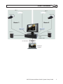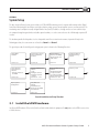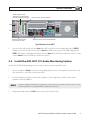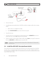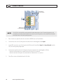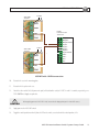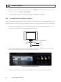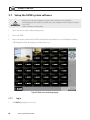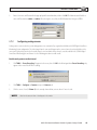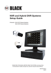
1
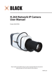
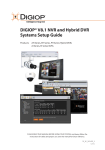
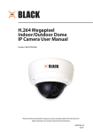
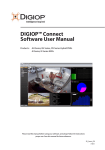
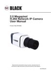
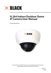
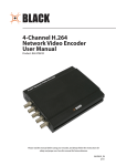
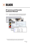
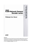
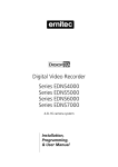
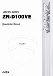
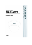
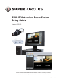
AVSI-IP2 Interview Room System Setup Guide Product: AVSI-IP2 PLEASE READ THIS MANUAL BEFORE USING YOUR SYSTEM, and always follow the instructions for safety and proper use. Save this manual for future reference. LE_AVSI-IP2_SQ CAUTION Operate this system only in environments where the temperature and humidity is within the recommended range. Operation in temperatures or at humidity levels outside the recommended range may cause electric shock and shorten the life of the product. Refer to the specifications for each system component for more information. LEGAL NOTICE Supercircuits products are designed to meet safety and performance standards with the use of specific Supercircuits authorized accessories. Supercircuits disclaims liability associated with the use of non-Supercircuits authorized accessories. The recording, transmission, or broadcast of any person’s voice without their consent or a court order is strictly prohibited by law. Supercircuits makes no representations concerning the legality of certain product applications such as the making, transmission, or recording of video and/or audio signals of others without their knowledge and/or consent. We encourage you to check and comply with all applicable local, state, and federal laws and regulations before engaging in any form of surveillance or any transmission of radio frequencies. SC Black is a registered trademark of Supercircuits, Inc. Microsoft, Windows, and Internet Explorer are either registered trademarks or trademarks of Microsoft Corporation in the United States and/or other countries. Other trademarks and trade names may be used in this document to refer to either the entities claiming the marks and names or their products. Supercircuits, Inc. disclaims any proprietary interest in trademarks and trade names other than its own. No part of this document may be reproduced or distributed in any form or by any means without the express written permission of Supercircuits, Inc. © 2011 Supercircuits, Inc. All rights reserved. 11000 N. Mopac Expressway, Building 300, Austin, TX 78759 Sales/Support: 1.800.335.9777 | Fax: 1.866.936.7257 ii www.supercircuits.com Table of Contents SECTION 1 SECTION 2 SECTION 3 SECTION 4 APPENDIX A APPENDIX B APPENDIX C APPENDIX D Systems Overview. . . . . . . . . . . . . . . . . . . . . . . . . . . . . . . . . . . . . . . . . . . . . . . . . . . . . . . . . . . . . . . . . . . . 2 Getting Started: Unpacking Your System . . . . . . . . . . . . . . . . . . . . . . . . . . . . . . . . . . . . . . . . . . . . . . . . 4 2.1 Unpacking the equipment. . . . . . . . . . . . . . . . . . . . . . . . . . . . . . . . . . . . . . . . . . . . . . . . . . . . . . . . . . . . . 4 2.2 What you need. . . . . . . . . . . . . . . . . . . . . . . . . . . . . . . . . . . . . . . . . . . . . . . . . . . . . . . . . . . . . . . . . . . . . . 4 System Setup. . . . . . . . . . . . . . . . . . . . . . . . . . . . . . . . . . . . . . . . . . . . . . . . . . . . . . . . . . . . . . . . . . . . . . . . 5 3.1 Install the hDVR hardware. . . . . . . . . . . . . . . . . . . . . . . . . . . . . . . . . . . . . . . . . . . . . . . . . . . . . . . . . . . . . 5 3.2 Install analog cameras. . . . . . . . . . . . . . . . . . . . . . . . . . . . . . . . . . . . . . . . . . . . . . . . . . . . . . . . . . . . . . . . 6 3.3 Connect analog cameras to the hDVR . . . . . . . . . . . . . . . . . . . . . . . . . . . . . . . . . . . . . . . . . . . . . . . . . . . 6 3.4 Install the ASK-4KIT-101 Audio Monitoring System . . . . . . . . . . . . . . . . . . . . . . . . . . . . . . . . . . . . . . . 7 3.5 Install the AVSI-SW1 Interview Room Switch. . . . . . . . . . . . . . . . . . . . . . . . . . . . . . . . . . . . . . . . . . . . . 8 3.6 Install and setup the monitor. . . . . . . . . . . . . . . . . . . . . . . . . . . . . . . . . . . . . . . . . . . . . . . . . . . . . . . . . 12 3.7 Setup the hDVR system software. . . . . . . . . . . . . . . . . . . . . . . . . . . . . . . . . . . . . . . . . . . . . . . . . . . . . . 14 3.7.1 Log in. . . . . . . . . . . . . . . . . . . . . . . . . . . . . . . . . . . . . . . . . . . . . . . . . . . . . . . . . . . . . . . . . . . . . . . . . 14 3.7.2 Configuring analog cameras. . . . . . . . . . . . . . . . . . . . . . . . . . . . . . . . . . . . . . . . . . . . . . . . . . . . . . 15 3.7.3 Add IP cameras to the system . . . . . . . . . . . . . . . . . . . . . . . . . . . . . . . . . . . . . . . . . . . . . . . . . . . . 16 3.7.4 Configure hDVR network settings. . . . . . . . . . . . . . . . . . . . . . . . . . . . . . . . . . . . . . . . . . . . . . . . . 16 3.7.5 Configure the hDVR to record using the AVSI-SW1 switch . . . . . . . . . . . . . . . . . . . . . . . . . . . . . 18 3.7.6 Set FPS and camera resolution. . . . . . . . . . . . . . . . . . . . . . . . . . . . . . . . . . . . . . . . . . . . . . . . . . . . 20 3.7.7 Configure recording schedule. . . . . . . . . . . . . . . . . . . . . . . . . . . . . . . . . . . . . . . . . . . . . . . . . . . . . 22 3.7.8 Naming a camera channel (optional). . . . . . . . . . . . . . . . . . . . . . . . . . . . . . . . . . . . . . . . . . . . . . 24 3.8 Testing the system. . . . . . . . . . . . . . . . . . . . . . . . . . . . . . . . . . . . . . . . . . . . . . . . . . . . . . . . . . . . . . . . . . 25 3.9 Export system configuration. . . . . . . . . . . . . . . . . . . . . . . . . . . . . . . . . . . . . . . . . . . . . . . . . . . . . . . . . . 25 3.10 Setup Reflection software . . . . . . . . . . . . . . . . . . . . . . . . . . . . . . . . . . . . . . . . . . . . . . . . . . . . . . . . . . . 26 3.10.1 Install Reflection . . . . . . . . . . . . . . . . . . . . . . . . . . . . . . . . . . . . . . . . . . . . . . . . . . . . . . . . . . . . . . . 27 3.10.2 Connect Reflection to the hDVR. . . . . . . . . . . . . . . . . . . . . . . . . . . . . . . . . . . . . . . . . . . . . . . . . . . 27 3.10.3 Using Reflection software. . . . . . . . . . . . . . . . . . . . . . . . . . . . . . . . . . . . . . . . . . . . . . . . . . . . . . . . 29 Installation Tips . . . . . . . . . . . . . . . . . . . . . . . . . . . . . . . . . . . . . . . . . . . . . . . . . . . . . . . . . . . . . . . . . . . . 30 FAQ. . . . . . . . . . . . . . . . . . . . . . . . . . . . . . . . . . . . . . . . . . . . . . . . . . . . . . . . . . . . . . . . . . . . . . . . . . . . . . . 31 Configuring SC Black IP Cameras . . . . . . . . . . . . . . . . . . . . . . . . . . . . . . . . . . . . . . . . . . . . . . . . . . . . . . 32 B.1 Check LAN for default IP address compatibility . . . . . . . . . . . . . . . . . . . . . . . . . . . . . . . . . . . . . . . . . . 32 B.2 Determine the network settings for each IP device. . . . . . . . . . . . . . . . . . . . . . . . . . . . . . . . . . . . . . . 33 B.3 Install the IPAdmin Tool (for SC Black IP cameras). . . . . . . . . . . . . . . . . . . . . . . . . . . . . . . . . . . . . . . . 34 B.4 Install and connect the IP camera/encoder to the LAN. . . . . . . . . . . . . . . . . . . . . . . . . . . . . . . . . . . . 34 B.5 Connect to the camera with Internet Explorer. . . . . . . . . . . . . . . . . . . . . . . . . . . . . . . . . . . . . . . . . . . 36 B.6 Repeat for all IP cameras. . . . . . . . . . . . . . . . . . . . . . . . . . . . . . . . . . . . . . . . . . . . . . . . . . . . . . . . . . . . . 37 Troubleshooting IP Cameras. . . . . . . . . . . . . . . . . . . . . . . . . . . . . . . . . . . . . . . . . . . . . . . . . . . . . . . . . . 38 C.1 IP camera reset. . . . . . . . . . . . . . . . . . . . . . . . . . . . . . . . . . . . . . . . . . . . . . . . . . . . . . . . . . . . . . . . . . . . . 38 C.2 Set to factory default settings. . . . . . . . . . . . . . . . . . . . . . . . . . . . . . . . . . . . . . . . . . . . . . . . . . . . . . . . . 38 C.3 Checking your Firmware . . . . . . . . . . . . . . . . . . . . . . . . . . . . . . . . . . . . . . . . . . . . . . . . . . . . . . . . . . . . . 38 Device Log. . . . . . . . . . . . . . . . . . . . . . . . . . . . . . . . . . . . . . . . . . . . . . . . . . . . . . . . . . . . . . . . . . . . . . . . . 39 AVSI-IP2 Interview Room Switch Systems Setup Guide 1 SECTION 1: SYSTEM OVERVIEW SECTION 1 Systems Overview The AVSI-IP2 system is a premium quality video and audio digital recording system ideally suited for indoor installation in rooms where interviews or interrogations are used as evidence for legal purposes. Recording can be started and stopped with one switch. The basic AVSI-IP2 system includes two SC Black, analog, high-resolution, color cameras, two audio monitoring systems (microphone with audio recorder), two Supercircuits® AVSI-SW1 interview room switches, one SC Black hybrid network digital network video recorder (hDVR) with a 19” widescreen LCD monitor, and the proper accessories to service two separate interview rooms. The hDVR can accommodate up to 4 analog cameras, 4 IP cameras, 4 audio channels, and four switches for expansion to multiple rooms and multiple facilities. SC Black hDVR security systems with the Digital Surveillance Monitoring System software features state-of-the-art management for advanced analog and IP cameras. It can be used to record and store digital video and images, control PTZ cameras, and improve the video quality (brightness, contrast, chroma U and V, hue, and gain) of analog cameras. It also includes several surveillance management features including system security and activity logging. All SC Black hDVRs, IP cameras and encoders include an IPAdmin Tool, a Microsoft® Windows®-based application for configuring IP camera network settings and installing updated firmware. Depending on your system, the IPAdmin Tool may be pre-installed on your hDVR and included on the documentation and software CD. After setting up and configuring your system with the Digital Surveillance Monitoring System software, use Reflection software (provided) to monitor your system. Reflection is a stand-alone Microsoft Windows based video dashboard that connects to the hDVR across a network. It provides remote viewing and management of live and recorded video with search, playback and download capabilities. Reflection accesses your cameras and stored video through your nDVR. It can be used to monitor multiple hDVR systems concurrently. This document is a guide to setting up your AVSI-IP2 system and the AVSI-SW1 switch. It refers to other documents for installing the cameras, configuring your monitor and the software embedded in the hDVR, and using Reflection software. For additional information, contact Supercircuits Support at: 1.800.335.9777. 2 www.supercircuits.com SECTION 1: SYSTEM OVERVIEW Mic 1 Mic 2 Camera 1 Camera 2 Room 2 Room 1 Switch 2 Switch 1 hDVR IPAdmin Tool Local Network Reflection Software AVSI-IP2 Interview Room Switch Systems Setup Guide 3 SECTION 2: GETTING STARTED: UNPACKING YOUR SYSTEM SECTION 2 Getting Started: Unpacking Your System 2.1 Unpacking the equipment Remove the equipment from its packaging and place it on a flat, clean surface. Inspect each item. If any visible damage is present, contact your supplier or Supercircuits for a replacement. Verify that your order is complete. Within your order you should find: • • • • • • • The number of cameras you ordered. Each camera includes a power supply, a software CD, and a Quick Installation Guide. 50’ video/power cable for each analog camera. Two AVSI-SW1 Interview Room Switches Two ASK-4KIT-101 microphone systems LCD monitor with the associated video and power cables, and documentation hDVR with power cables, keyboard and mouse, remote control, software CD, and documentation. DC12-500R Power Supply Refer to the user manual for the product for a list of specific items included with the product. The user manual may be provided on the CD included with the product. NOTE Large systems may be shipped in several cartons. 2.2 What you need To install the AVSI-SW1 Interview Room Switch, you need: • • • • • 4 5/64” hex key #1 Phillips screwdriver Small slot screwdriver Screws and tools for mounting the wall plate Cat5 or equivalent signal wire www.supercircuits.com SECTION 3: SYSTEM SETUP SECTION 3 System Setup The basic Interview Room System system includes an SC Black hDVR monitoring console computer with monitor and the Digital Surveillance Monitoring System software, two high-resolution analog cameras, two microphone systems, and two switches. The monitoring console computer is usually configured with a fixed (static) IP addresses. Analog cameras are connected directly to the computer through integrated video and audio capture hardware, or can be connected across the LAN through an optional IP encoder. The hardware provided in this product is selected to provide surveillance to two interview rooms. In pursuit of clarity in the following procedure, these two rooms are referred to as Room 1 and Room 2. The general procedure for installing and setting up your system is shown in the following flow chart. Install hDVR hardware. Install analog cameras in their surveillance locations: Connect analog cameras to the hDVR: - Connect video and audio cables Install ASK-4KIT-101 Audio Monitoring Systems Sections 3.1 Sections 3.2 Section 3.3 Sections 3.4 Setup the hDVR System Software - Configure AVSI-SW1 - Set fps, resolution, recording schedule - Name camera channels Section 3.7.5 - 3.7.8 Test the system Install AVSI-SW1 Interview Room Switches - Connect switches to the hDVR Sections 3.5 Setup the hDVR System Software - Login - Configure cameras - Configure network settings Section 3.7.1 - 3.7.4 Export System Configuration Setup Reflection Software - Install Reflection - Connect to the hDVR - Use Reflection Section 3.9 Section 3.10 Sections 3.8 General Installation and Setup Flowchart 3.1 Install the hDVR hardware Install your hDVR hardware. Refer to the Quick Start Guide included with the equipment. Do not power on the hDVR or connect it to a LAN at this time. AVSI-IP2 Interview Room Switch Systems Setup Guide 5 SECTION 3: SYSTEM SETUP 3.2 Install analog cameras Do the following: 1. Install and setup the two analog cameras in the two interview rooms in accordance with the installation instructions provided. Ensure that the camera location will provide the best field of view. 2. Route the video/power extension cable from each camera to the location where the hDVR is installed. NOTE Typically, the power connectors on video extension cables are different at each end. When routing these cables, ensure that the connectors match the devices they attach to. 3.3 Connect analog cameras to the hDVR Analog cameras are assigned to camera channels in the SC Black Digital Surveillance Monitoring System software by attaching them to the video connector associated with the channel. 1. Connect the multi-channel video adapter dongle to the video capture card of the computer. The video capture card provides DVI-style connector. Notice that all BNC connectors are labeled for the channel number assigned to the connector. NOTE Although a multi-channel video adapter dongle is provided with the hDVR, only eight analog video channels can be used with the basic system. It can include IP cameras after the purchase and installation of IP channel licenses. 8-channel video adapter dongle 6 www.supercircuits.com SECTION 3: SYSTEM SETUP Video Capture Card with DVI-style Connector for Video Adapter Dongle I/O Connector Terminal Block CH 4 .. CH 1 Audio Input Channels (4-channel PC card) VGA Connector for the LCD Monitor Typical Backpanel for an hDVR 2. Connect the video cable from the camera in Room 1 to the BNC connector on the video adapter dongle labeled VIDEO 1. Similarly, connect the video cable from the camera in Room 2 to the BNC connector on the video adapter dongle labeled VIDEO 2. This hardware configuration will assign the camera in Room 1 to the hDVR system surveillance channel 1, and the camera in Room 2 to the to the hDVR system surveillance channel 2. 3.4 Install the ASK-4KIT-101 Audio Monitoring System Install the ASK-4KIT-101 Audio Monitoring System in accordance with the instructions provided in the kit. 1. Place one microphone in Room 1, in the best location to pickup audio in the room. The microphone must be within 15 feet of the sound source. Locate its Base Station near the hDVR. 2. Install the wiring between the Base Station and the microphone. The wire length between the Base Station and the microphone can be up to 1000 feet. NOTE 3. 2-conductor, 22 gauge shielded cable with a 24 gauge drain is required to connect the microphone to the Base Station. A 100’ roll of cable is included with the system (additional cable is available from Supercircuits). Plug the power adapter into the +12 VDC connector on the back of the Base Station. AVSI-IP2 Interview Room Switch Systems Setup Guide 7 SECTION 3: SYSTEM SETUP Wire between Mic and Base Station Microphone Base Station Power Adapter RCA Cables 4. Power on the Base Station. 5. Use the Operating Instructions provided with the ASK-4KIT-101 to verify that the microphone and Base Station are working properly: a. Adjust the volume to a level appropriate for recording. b. Push the PUSH FOR PLAYBACK button to activate and deactivate the speaker. 6. Power off the Base Station. 7. Attach white lead of the RCA cable provided with the Audio Monitoring System to the AUDIO OUTPUT connector on the back of the Base Station, and to the CH 1 audio input on the back of the hDVR. 8. Repeat the steps above to install and setup the microphone and Base Station for Room 2, connecting the RCA cable from the Base Station AUDIO OUTPUT to the CH 2 audio input on the back of the hDVR. NOTE The audio input on CH 1 is always associated with the video input on VIDEO 1. Similarly, audio input CH 2 is always associated with the VIDEO 1 input. 3.5 Install the AVSI-SW1 Interview Room Switch The Interview Room Switch is installed and configured with the hDVR system to start and stop recording the video and audio from the room the switch is associated with. Using the installation instructions and the system software configuration included herein, when the switch is down, the hDVR will record the camera and audio from the room the switch is associated with. When the switch is up, the hDVR will stop the recording. 8 www.supercircuits.com SECTION 3: SYSTEM SETUP NOTE 1. To use advanced features of the switch, such as lighting the LED associated with the switch position or receiving confirmation at the switch when the DVR is recording, please contact the Supercircuits Support team for recommendations. Remove the face plate by removing the two hex screws. Face Plate Face Plate Screw Case Mounting Plate Green: DVR in Standby Wiring Knockout Red: DVR Recording Face Plate Screw CAUTION 2. Remove the AVSI-SW1 face plate carefully. It is connected to wires that are attached to the mounting plate behind it. Remove the two screws securing the case to the mounting plate. Screws Securing Case 3. Determine the path for routing the connecting wires and remove the case or mounting plate knockout as required. 4. Anchor the mounting plate to the wall at the best location for Room 1 using appropriate hardware. AVSI-IP2 Interview Room Switch Systems Setup Guide 9 SECTION 3: SYSTEM SETUP Mounting Screw Holes + 12 V DC Jumper Input Output Mounting Screw Holes NOTE The AVSI-SW1 is wired to a DVR sensor input to control a recorder, and to a power source. The control wiring connects to the terminal block with the black and white leads from the switch; the power wiring connects to the terminal block with the black and red leads from the switch, and is polarity dependent. 5. Route Cat5 wire (or equivalent) from the switch to the hDVR IO Connector Terminal block. 6. At the switch, connect the Cat5 wire pair to the terminals on the mounting plate marked Input 7. At your DVR, connect the same Cat5 wire pair to the IO Connector Terminal block Input 1 and Input Ground terminals. This connection is polarity independent. 8. At the switch, attach the another Cat5 wire pair to the power terminals on the mounting plate as follows: – Attach the solid color wire to the terminal where the red wire (V+) is attached. – Attach the other wire of the pair to the terminal where the black wire (V–) is attached. 9. Trim off excess wire and insulation from the Cat5 cable. 10 www.supercircuits.com SECTION 3: SYSTEM SETUP 12 VDC AVSI-SW1 Switch 1 hDVR I/O Connector Terminals 12 VDC AVSI-SW1 Switch 2 Output 1 Output 2 Output Ground Input 1 Input 2 Input 3 Input 4 Input Ground TRX + TRX − RX + RX − AVSI-SW1 Switch - hDVR Interconnections 10. Reattach the case to the mounting plate. 11. Reattach the face plate to the case. 12. Attach the other end of the Cat5 power wire pair (solid color/white-color) to 12 VDC V+ and V– terminals, respectively, on a DC12-500R Power Supply or equivalent. CAUTION Before applying power to the AVSI-SW1 switch, ensure that the voltage polarity at the switch will be correct. 13. Apply power to the AVSI-SW1 switch. 14. Toggle the switch position and verify that the LED on the switch, associated with the switch position, is lit. AVSI-IP2 Interview Room Switch Systems Setup Guide 11 SECTION 3: SYSTEM SETUP 15. Repeat the steps above to install and setup the AVSI-SW1 switch for Room 2, connecting the control terminal in the switch to the IO Connector terminals Input 2 and Input Ground. 16. Set the toggle switch on both AVSI-SW1 switches to the up (green LED) position for standby mode. 3.6 Install and setup the monitor If your system includes the Supercircuits LCD17-5, LCD19-5, LDC19W-7, or LCD22W-7 monitor, use the following procedure to setup the monitor. Otherwise, follow the instructions provided by the manufacturer to setup your monitor and connect it to the computer. 1. Find the monitor assembly and base. Use the screw provided to attach the base to the monitor support bracket. The screw may be attached to the underside of the monitor support bracket or in the base. Support Bracket Base Screw 2. Attach the VGA cable provided with the monitor to the VGA input connector on the lower back side of the monitor. Attach the other end of the VGA cable to the VGA connector on the back of the computer. Inputs on the lower back side of monitor 3. 12 Attach a stereo audio cable with a 3.5 mm jack into the PC AUDIO connector on the lower back side of the monitor. www.supercircuits.com SECTION 3: SYSTEM SETUP 4. Attach the other end of the audio cable to the audio line-out connector on the back of the hDVR. The audio line out connector is color coded light green. 5. Attach the power cable to the monitor and plug it into a grounded power outlet. 6. Press the Power button to power on the monitor. The Power button is located in the control panel on the right side of the monitor. SOURCE Move up in menu Move down in menu Move right in menu or volume up Move left in menu or volume down MENU (open/close) Power Audio output Monitor control panel 7. Press the SOURCE button on the monitor control panel to open the video source menu. Use the p and q buttons on the control panel to highlight PC, and then press the MENU button to select that interface. An indication will appear on the screen confirming your selection. 8. Power off the monitor. AVSI-IP2 Interview Room Switch Systems Setup Guide 13 SECTION 3: SYSTEM SETUP 3.7 Setup the hDVR system software ! WARNING To help prevent personal injury or damage to the equipment, make sure all power sources are grounded. 1. Before applying power to the computer, verify that the power source configuration switch on the back of the computer is set to 110 VAC. 2. Make sure all cables are securely attached. 1. Power on the cameras and the audio monitoring systems. 2. Power on the hDVR. 3. Power on the monitor and wait until the hDVR is initialized. When fully initialized, the server will display the following SC Black Digital Surveillance Monitoring System multi-image screen. Typical SC Black server multi-image display 3.7.1 1. 14 Log in Click LOG IN (lower right corner of screen). www.supercircuits.com SECTION 3: SYSTEM SETUP 2. Enter a User name and Password in the pop-up Input Password window, and then click OK. The Administrator default User name and Password are admin and admin. When the login is successful, the LOG IN button label changes to TOOLS. 3.7.2 Configuring analog cameras Analog cameras connected to the system during power on are automatically recognized and added to the hDVR Digital Surveillance Monitoring System configuration. The video image from the camera will appear on the camera channel associated with the video connector it is physically attached to. An audio channel, associated with a video channel, must be enabled in the SC Black Digital Surveillance Monitoring System software. Use the following procedure to enable audio. Enable analog camera audio channel 1. Click TOOLS > Pause Recording if it appears in the menu, then click OK in the Warning window. Pause Recording only appears in the menu if the hDVR is recording. 2. Click TOOLS > Configure > Cameras to open the Camera tab. 3. Click the camera 1 icon (for Room 1). In the example shown below, camera channel 1 was selected. NOTE Video from the camera in Room 1 should appear in the window. AVSI-IP2 Interview Room Switch Systems Setup Guide 15 SECTION 3: SYSTEM SETUP Camera Channel Icon 4. Click the Enable Audio checkbox to select it. 5. Repeat this procedure for camera channel 2 (Room 2). 6. Click the Close button at the bottom of the window. 7. Repeat this procedure for camera channel 2 (Room 2). 3.7.3 Enable Audio Option Add IP cameras to the system IP cameras are not part of the basic AVSI-IP2 system, but can be added for additional video coverage from an interview room, or to expand the system to include other interview rooms. (See the appendix Configuring SC Black IP Cameras.) Additional licensing may be required. 3.7.4 Configure hDVR network settings If the hDVR will be used on a network, use the following procedure to configure the network settings. 16 www.supercircuits.com SECTION 3: SYSTEM SETUP NOTE The preferred method to view, search, download, and archive recorded video is Reflection software. Reflection access the hDVR from a Microsoft Windows based system across an Ethernet connection. A simple Ethernet link between the hDVR and another computer can be established using an Ethernet crossover cable. 1. Click TOOLS > Configure > Network to open Network tab. 2. If not already check marked, click the Enable Network option in the upper left corner to select it. 3. In the Enable Network frame, click the Edit button to open the Network Settings window. AVSI-IP2 Interview Room Switch Systems Setup Guide 17 SECTION 3: SYSTEM SETUP 4. In the Network Connection Settings window, select the network options you prefer, then click OK. NOTE 5. To access the Internet from the system, you must define a DNS server. Contact your system administrator for more information. Attach the Ethernet LAN cable to your hDVR. 3.7.5 Configure the hDVR to record using the AVSI-SW1 switch The wiring of the switch for each room to the hDVR (see above) can control when video and audio from an interview room will be recorded. With the software configuration setup recommended below, when the switch for Room 1 is down, the red LED is lit and the video and audio from Room 1 (camera channel 1) is being recorded. When that switch is up, the green LED (hDVR standby) is lit and the video and audio from Room 1 is not being recorded. The switch for Room 2 will function the same way for the video and audio in Room 2. The recording of Room 1 and Room 2 occur independent of each other. To setup the system software configuration, do the following: 1. 18 After logging into the system software, click TOOLS > Configure > Sensor/Control to open the configuration window shown below. www.supercircuits.com SECTION 3: SYSTEM SETUP Select: Enable Sensors and Controls Select: Sensor 1 Select: Camera 1 Sensor Recording Time = Sensor Active Duration Recording Mode = Normal Sensor Type = N/O 2. In the Sensor/Control tab, click the following parameters to select them: – Select the Enable Sensors and Controls checkbox – In the Sensor frame, select the sensor 1 icon. When selected, the sensor 1 icon will be marked as shown above. – In the Camera associated with selected Sensor frame, select the icon for camera channel 1. When selected, the camera channel 1 icon will be highlighted as shown above. – In the Sensor Recording Time frame, select: Sensor Active Duration – In the Recording Mode frame, select: Normal – In the Sensor Type frame, select: N/O (Normally Open) 3. Click Close to save the configuration setup for Room 1. 4. Click TOOLS > Configure > Sensors/Controls again to setup switch 2 for Room 2. AVSI-IP2 Interview Room Switch Systems Setup Guide 19 SECTION 3: SYSTEM SETUP Select: Enable Sensors and Controls Select: Sensor 2 Select: Camera 2 Sensor Recording Time = Sensor Active Duration Recording Mode = Normal Sensor Type = N/O 5. In the Sensor/Control tab, click the following parameters to select them: – Select the Enable Sensors and Controls checkbox – In the Sensor frame, select the sensor 2 icon. When selected, the sensor 2 icon will be marked as shown above. – In the Camera associated with selected Sensor frame, select the icon for camera channel 2. When selected, the camera channel 2 icon will be highlighted as shown above. – In the Sensor Recording Time frame, select: Sensor Active Duration – In the Recording Mode frame, select: Normal – In the Sensor Type frame, select: N/O (Normally Open) 6. Click Close to save the configuration setup for Room 2. 3.7.6 Set FPS and camera resolution The frame rate and resolution settings determine how smooth the recorded video from the camera appears, and how clear it appears. The optimal frame rate is 30 frames per second (fps), and the clearest video is received when the camera is set to the highest resolution (image size). The system defaults to low frame rates and resolutions. 20 www.supercircuits.com SECTION 3: SYSTEM SETUP NOTE The higher the fps and resolution settings, the faster the hard drive space is used. To change the fps and resolution settings, click TOOLS > Configure > FPS / Resolution. Allocating FPS and Resolution to each camera You can allocate a resolution and a portion of the available fps for that resolution to each camera. NOTE To change the fps or resolution setting, the camera cannot be recording. Make sure recording is paused before making any changes to these settings. If you do not pause recording, the options are grayed out so you cannot access them. 1. Click TOOLS > Pause to stop the recording. The available cameras are highlighted. 2. Place a check mark in the FPS and Resolution Setting per Camera checkbox. This activates the feature. 3. Select the camera to be set-up from the available cameras. AVSI-IP2 Interview Room Switch Systems Setup Guide 21 SECTION 3: SYSTEM SETUP 4. Select the desired Resolution setting for each camera (channel) you want to configure. (The available fps for that resolution will be updated to the left of the resolution selected.) 5. Use the slide control to set the fps for each camera you want to configure. As you move the slide control beside the camera, the values in the Use/Max column change correspondingly. The Resolution column indicates the current setting for the selected camera. In this example, the slide control is set to 30/30 frames per second at a resolution of 320 x 240. NOTE: The camera can be set to a higher resolution. 6. Click Close to save your settings. 3.7.7 Configure recording schedule The SC Black server can be configured for continuous recording, motion detection recording (initiated by motion detection), sensor activated recording (occurs when a sensor, such as the AVSI-SW1 switch, is active), or combinations of these options during different times. In the following procedure, the schedule will be configured for sensor activation recording only. 1. 22 After logging into the system software, click TOOLS > Configure > Schedule to open the record scheduling configuration window shown below. www.supercircuits.com SECTION 3: SYSTEM SETUP Select: Use Schedule Select: Camera 1 Set all timeslots to “S” (Sensor Activated) Click to Set Selected Timeslots to Sensor Activated Recording 2. In the Schedule tab, click the following parameters to select them: – Select the Use Schedule checkbox – In the Record Option frame, select the camera 1 icon. When selected, the icon will be colored blue as shown above. – In the Record Option frame, use a mouse and drag a box over all timeslots (00:00 – 23:59, Workday – Holiday) to select them. – Click the Sensor Activated button. All timeslots should be marked with “S”. 3. Click the Copy to button. In the Copy Schedule window, click the checkbox for Camera 2 (see below). 4. Click the OK button to apply the same schedule to the camera in Room 2 and to close the Copy Schedule window. AVSI-IP2 Interview Room Switch Systems Setup Guide 23 SECTION 3: SYSTEM SETUP 5. In the Schedule tab, click the Close button to save your configuration changes. 3.7.8 Naming a camera channel (optional) The camera channel can be assigned a name that appears on the video image. To rename a camera channel: 1. Click TOOLS > Configure to open the configuration (Preferences) window. By default, the Camera tab is opened. 2. In the Select Camera frame, click on an analog camera channel you want to name. In the example below, camera channel 1 is selected. 3. In the Camera Name frame, click the keyboard icon. Note that the default name for the channel is “Camera 1”. 4. Click the character buttons on the pop-up keyboard (or use the system keyboard) to enter a new name. To select an uppercase letter, click the Shift button, then click the character button. The entry will appear in the field at the bottom of the keyboard window. 5. After selecting the new camera name, click the Input button in the keyboard window. The keyboard window will close. 24 www.supercircuits.com SECTION 3: SYSTEM SETUP 6. To save the entry, click Close in the Camera tab. 3.8 Testing the system To test the system, do the following: 1. Verify that both interview room switches are in the up (standby) position, and the green LED is lit. 2. View the hDVR multi-camera display (home) screen. Verify that video images are received from the cameras in Room 1 (video channel 1) and Room 2 (video channel 2). Also verify that the video images from channel 1 and channel 2 are not surrounded by a red border (hDVR is not recording those channels). 3. Toggle the switch for Room 1 to the down (record) position. The red LED on the switch should light, and at the system display, a red border should surround only the video channel 1 image. 4. Toggle the switch for Room 1 to the up position. At the system display, verify that the red border around video channel 1 disappeared. 5. Toggle the switch for Room 2 to the down (record) position. The red LED on the switch should light, and at the system display, a red border should surround only the video channel 2 image. 6. Toggle the switch for Room 2 to the up position. At the system display, verify that the red border around video channel 2 disappeared. 3.9 Export system configuration Although catastrophic failures are extremely rare in the SC Black system, having the system configuration file backed up enables you to quickly restore the system configuration if that becomes necessary. Also, the configuration file can be used to pre-configure other systems. Whenever changes are made to the system configuration, export the system configuration to an external storage media. To export the system configuration: 1. Click TOOLS > Configure to open the configuration (Preferences) window. By default, the Camera tab is opened. 2. Open the System tab. AVSI-IP2 Interview Room Switch Systems Setup Guide 25 SECTION 4: INSTALLATION TIPS Export configuration 3. In the Export/Import frame in lower-right corner of the System tab, click Export. 4. Follow the on-screen instructions to identify the location, such as a CD or USB thumb drive, where the file will be saved. NOTE The system configuration file is usually smaller than 50 KB. It is named: DIGIOPIPDEVICELIST.DVR 6. Wait until the message “Export successfully completed ...” appears before continuing. 7. Store the backed up configuration file media in a secure location. 3.10 Setup Reflection software Reflection software should be installed on a Windows PC that can connect to the hDVR across a LAN. If the LAN is configured to allow access to the hDVR through the internet, the Reflection PC can be anywhere that has high-speed internet access. Reflection runs on Microsoft Windows XP Professional with Service Pack 2 (SP2), Windows Vista, and Windows 7. During the installation process, the Reflection installer will also load Microsoft .NET Framework if the version it requires is not installed. For more information about Reflection, refer to the Reflection Software User Manual or the Reflection Software Quick Start Guide 26 www.supercircuits.com SECTION 4: INSTALLATION TIPS 3.10.1 Install Reflection Reflection is provided on the Application disk included with your hDVR hardware. 1. Insert the Application disk into a DVD drive on your computer and find the ReflectionInstaller.exe file. Double click or Run this file to start the installation. 2. Follow the screen prompts to install Reflection on your computer. After you click Finish, the SC icon (see below) will appear on the desktop and in your Windows Start Menu. 3.10.2 Connect Reflection to the hDVR 1. Start Reflection by double clicking the desktop icon or using the Windows Start menu. 2. Click Login at the bottom of the dialog box to open Reflection. 3. In the Reflection main window, click Configuration > Add > Digiop Video Server in the upper left corner of the window. AVSI-IP2 Interview Room Switch Systems Setup Guide 27 SECTION 4: INSTALLATION TIPS 4. Enter the DVR configuration fields with the information necessary to identify your hDVR. It should include: —— —— —— —— —— —— IP Address or Hostname – This is the IP address or the host name of the hDVR. Username – This is the username that is to be used to access the hDVR. Password – This is the password associated with the Username. Time zone – Select the time zone where the hDVR is located. Name (optional) – This is the name that identifies the server within Reflection. Description (optional) – This is for a description for the system. 5. Click Save. Reflection will display the Name of the hDVR you added in the left panel Systems list. 6. To open a connection to the hDVR you added, double-click the Name in the left panel. 28 www.supercircuits.com SECTION 4: INSTALLATION TIPS 3.10.3 Using Reflection software Reflection is provided on the Application disk included with your hDVR. Refer to the Reflection User Manual for complete installation and usage instructions. AVSI-IP2 Interview Room Switch Systems Setup Guide 29 SECTION 4: INSTALLATION TIPS SECTION 4 Installation Tips Camera placement Use the information included in the packaging of your camera to mount and connect the unit to power and video cables. Plan your camera installation carefully. Identify the locations where cameras will provide the best coverage, considering: • • • Field of view – Cameras must be positioned so they can effectively view the entire area that must be monitored. Lighting – Is there enough light in the field for the camera to “see” clearly? Is there intense light from the sun or shiny objects that reflect onto the camera lens? These conditions may affect the video quality and camera performance. Ease of installation – Must be able to install the camera at the location, considering mounting hardware requirements, temperature, dust, moisture, etc. Cable runs LAN/power and video coaxial cables can be run almost anywhere, and are frequently routed above drop/acoustic ceilings because of the ease of installation. For added security, we recommend you run your cables in areas with limited access to prevent tampering. Avoid running the cable near high voltage appliances such as fluorescent lighting. Electrical noise and magnetic fields produced by these devices may affect video signal quality. A 100’ Ethernet cable is shipped with every camera in your system. Custom-cut cables are also available from Supercircuits. hDVR placement Your monitoring and recording equipment is central to the accurate capture of video evidence and constant surveillance. Supercircuits strongly suggests that it be installed in a secure location with access limited to authorized personnel. Additionally, hDVRs generate heat and should be placed in a well ventilated area. Excessive heat will reduce the life span and reliability of the equipment. The monitor does NOT need to be on for recording to take place. hDVRs will output and record video regardless of the operational status of the monitor. Uninterruptible power supplies It is strongly suggested that power to the entire system be routed through the uninterruptible power supply (UPS). These devices will keep your security system running through most power outages, in addition to providing excellent voltage surge and drop protection. The UPS provided should support your video recorder, the audio base stations, and the cameras included with the basic system. It is not necessary to power the monitor through a UPS. 30 www.supercircuits.com APPENDIX A: FAQ APPENDIX A FAQ QQ I cannot see video from my camera at the hDVR. What can I do to restore the video? AA Reset the camera. Can you see all the cameras on your network with this utility? Check the camera lens for blockages, dirt, etc. and clean if needed. Use the BNC adapter with the camera or the LOOP connector to check video. If video is good but still can’t connect, check the cable between the camera and the DVR. QQ Everything is hooked up and working, but the video that is recorded is jerky and not smooth. Is there something wrong with my system? AA Smoothness of recorded video is dependent upon several factors including compression level, capture size, and the maximum frame rate of your recorder. Most hDVRs record at frame rates of 30, 90, or 120 frames per second (fps). The frame rate of your hDVR is divided between each channel being recorded, unless configured otherwise in the Resolution/FPS tab. For example, a 90 fps DVR recording 4 channels will record 22.5 fps per channel, which will appear very smooth. A 120 fps hDVR recording 9 channels will record 13 fps, which will appear less smooth and fluid, particularly when compared to a TV broadcast at about 30 fps. If there are irregular gaps in the video, or a momentary loss of video, there could be problems in the system. Call Supercircuits at 1-800-335-9777 for assistance. QQ Why can’t I get a good picture from one of my cameras? The camera’s power light is blinking or flickering. AA This is usually a symptom of low voltage at the camera. You may have a cable run that is too long, a defective cable, or an insufficient power supply. Try using a better quality cable, or plug the power adapter directly into the camera to bypass the cable all together. QQ I installed the cables to my analog video equipment, but the power plug won’t fit into the camera or the power adapter: AA Chances are you’ve run the cable backwards. Only one end of the camera cables supplied by Supercircuits will fit the camera, while only the other end will fit the power adapter. The cable will need to be pulled, and run the other direction. AVSI-IP2 Interview Room Switch Systems Setup Guide 31 APPENDIX B: CONFIGURING SC BLACK IP CAMERAS APPENDIX B Configuring SC Black IP Cameras You can add up to four analog cameras and up to four IP cameras to the Interview Room System with the BLK-NX1008500G hDVR. Analog cameras connect directly to the hDVR, but IP cameras connect to the hDVR through a LAN. Additionally, SC Black IP cameras are factory configured with the same, static IP address (network settings): IP address: 192.168.0.100 Subnet mask: 255.255.255.0 Gateway: 192.168.0.1 Therefore, before connecting any new SC Black IP camera or encoder to the LAN, check the LAN for compatibility to avoid addressing conflicts with other devices. B.1 Check LAN for default IP address compatibility All SC Black cameras and encoders are factory configured with the static IP address 192.168.0.100. To avoid network conflicts, check the LAN before connecting your camera to ensure that network conflicts won’t occur: 1. 2. At a Microsoft Windows computer attached to the LAN subnet where the camera will be connected (surveillance network), open a Command Prompt window. a. Click the Windows Start button and select Run. b. In the Open field, enter “cmd”, then click OK. At the command prompt, use the ping command to see if the default IP address of your IP device is in use. If the default static IP address is 192.168.0.100, enter: ping 192.168.0.100 32 www.supercircuits.com APPENDIX B: CONFIGURING SC BLACK IP CAMERAS The “Request timed out” response indicates that the IP address is not currently in use and the camera can probably be connected without causing conflicts. A “Reply from ..” message received from a ping indicates that an active device with that IP address exists on the network, and new devices with that address shouldn’t be attached to that network without first changing the network settings of the device. Use the manufacturer’s recommended procedure for changing the address before attaching it to the LAN. For SC Black cameras and encoders: To change the IP address before connecting it to the surveillance LAN: NOTE 3. - Determine the new IP address for the device using the procedure outlined in section 3.2 below. - Setup the device temporarily on a LAN where 192.168.0.100 is not in use and power it on. - Install the IPAdmin Tool on a computer on the LAN where the device is temporarily located (see below) - Use the IPAdmin Tool to setup the new IP address, subnet mask, and gateway for the device (see below) - Power off the device and disconnect it from the LAN where it was temporarily setup. It will retain the new network settings you configured it with. Use the ping command to verify that the static IP addresses of other devices in your surveillance system won’t conflict with devices already installed on the LAN. B.2 Determine the network settings for each IP device Consult with your LAN network administrator to obtain a list of network settings for each IP device, including the hDVR and all cameras and encoders, you will attach to your LAN. You must use a static IP address for your surveillance system to ensure connectability with the hDVR. The table included in Appendix E may be useful for logging your network settings. To determine (or verify) which IP addresses are available on your surveillance network, use the ping command as described above to test each address. AVSI-IP2 Interview Room Switch Systems Setup Guide 33 APPENDIX B CONFIGURING SC BLACK IP CAMERAS S B.3 Install the IPAdmin Tool (for SC Black IP cameras) The IPAdmin Tool, included on the CD disk with all SC Black IP cameras and encoders, will discover all SC Black IP cameras and encoders attached to your network. It is used to perform the initial network setup for each camera and encoder, and install firmware updates. The IPAdmin Tool can be loaded on a Microsoft Windows XP, Vista, or Windows 7 operating system. To install the IPAdmin Tool, do the following: 1. Create a directory on your computer hard drive for the IPAdmin Tool application files. 2. Insert the CD disk provided with your camera or encoder into your computer’s CD ROM drive and open the CD in a Windows Explorer window. 3. Copy the files IPAdminTool.exe, CgiUtil.dll, and IPAdminTool.dll from the CD to your new directory. B.4 Install and connect the IP camera/encoder to the LAN 1. Install the IP camera or encoder in the surveillance location in accordance documentation provided with the camera. 2. Connect your IP camera to the LAN. 3. In the Windows directory where you installed IPAdmin Tool, double click IPAdminTool.exe to start the application. When the IPAdmin Tool starts, it will discover all of the support IP cameras and encoders that exist on the network. The discovery process may take several minutes. IPAdmin Tool discovered 192.168.0.100 NOTE 34 When a camera is powered on, it will not respond to network commands until it is fully initialized. The initialization process can take up to 2 minutes. www.supercircuits.com APPENDIX B: CONFIGURING SC BLACK IP CAMERAS 4. In the Product list, find the entry with the same MAC address as the camera you are configuring. If the camera is not shown, click Refresh repeatedly to update the list. 5. Right click on the entry for your camera and select IP Address. 6. In the IP Setup window: a. Select the Static option if it is not selected. This option is required to record camera video by an hDVR. IP Setup window b. Enter the new IP address, subnet mask, and gateway address into the appropriate fields. c. Click SETUP. A Login window will open. d. In the Login window, enter the ID and PW (password) for your camera and click Login. The default administrator values for the ID and PW are root and pass. After entering the ID and PW, the IP Setup window will close. AVSI-IP2 Interview Room Switch Systems Setup Guide 35 APPENDIX B: CONFIGURING SC BLACK IP CAMERAS 7. In the IPAdmin Tool window, click Refresh and verify that the entry representing the camera now shows the new IP address. B.5 Connect to the camera with Internet Explorer To further test the connectability of the camera (network settings) and verify video streaming: 1. Open Microsoft Internet Explorer (IE). 2. In the Internet address field, enter the newly configured IP address for your camera in the format: http://<IP address>/ Where <IP address> is the IP address of your camera. For example, if the new IP address of the camera is 192.168.1.201, enter: http://192.168.1.201 3. If prompted to install an ActiveX control such as AxNVC.cab, follow screen prompts to install the software. IE prompt to install ActiveX control 36 www.supercircuits.com APPENDIX B: CONFIGURING SC BLACK IP CAMERAS NOTE If you cannot see live video after logging into your camera and the following message appears: “Can not Create XMLDOMDocument Install MSXML4.0”, download and install the MS XML 4.0 library. The library can be found at: http://www.microsoft.com/downloads/details.aspx?familyid=3144B72B-B4F2-46DA-B4B6-C5D7485F2B42&displaylang=en After loading ActiveX controls and updating your XML library, a video stream from the camera should appear. 4. Adjust the camera video settings, setup the motion detection configuration, etc. if necessary. 5. Verify connectability to the device using network based software as suggested by the manufacturer. For SC Black cameras and encoders, see Connect to the camera with IE below. B.6 Repeat for all IP cameras Repeat the step above for each camera or encoder you install. Setup one camera at a time to prevent network conflicts between cameras that have the same initial IP address. AVSI-IP2 Interview Room Switch Systems Setup Guide 37 APPENDIX C: TROUBLESHOOTING IP CAMERAS APPENDIX C Troubleshooting IP Cameras C.1 IP camera reset To reset the camera while it is in use: NOTE The BLK-IPD101 camera cannot be reset. 1. Press and hold the Reset button for 3 seconds. 2. Wait for the camera to reboot. C.2 Set to factory default settings The camera network settings can be forced to the initial (factory default) settings: • • • • • IP address – reset to 192.168.0.100 Subnet mask – reset to 255.255.255.0 Gateway – reset to 192.168.0.1 User ID – reset to root Password – reset to pass To force the camera to the factory settings: 1. Disconnect the power (adapter) from the device. 2. While pressing and holding down the Reset button, connect the power to the camera. 3. Release the Reset button 5 seconds after powering on the camera. 4. Wait for the camera to reboot. C.3 Checking your Firmware Firmware is software embedded in the camera that determines many of its features and functionality. The current firmware version of your camera can be found by viewing video from the camera in Internet Explorer (IE), and then clicking SETUP > About > Version. To replace or update the firmware in your camera, contact the Supercircuits Support Team. 38 www.supercircuits.com APPENDIX D: DEVICE LOG APPENDIX D Device Log The following table is provided as an aid to setting up and logging the IP devices on your network. hDVR Description/SKU MAC address IP Address Subnet Mask Gateway Location IP Device Summary AVSI-IP2 Interview Room Switch Systems Setup Guide 39 APPENDIX D: DEVICE LOG Analog Camera Device Summary hDVR Channel Camera Model Audio (Y/N) 1 2 3 4 5 6 7 8 9 10 11 12 13 14 15 16 40 www.supercircuits.com Location SECTION AVSI-IP2 Interview Room Switch Systems Setup Guide 41