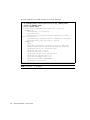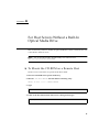
1
Sun Fire™ V210 and V240 Server
Netra™ 240 Server
CPU Upgrade Guide
Sun Microsystems, Inc.
4150 Network Circle
Santa Clara, CA 95054 U.S.A.
650-960-1300
Part No. 817-4146-11
January 2004, Revision A
Send comments about this document to: [email protected]
Copyright 2004 Sun Microsystems, Inc., 4150 Network Circle, Santa Clara, California 95054, U.S.A. All rights reserved.
Sun Microsystems, Inc. has intellectual property rights relating to technology embodied in the product that is described in this document. In
particular, and without limitation, these intellectual property rights may include one or more of the U.S. patents listed at
http://www.sun.com/patents and one or more additional patents or pending patent applications in the U.S. and in other countries.
This document and the product to which it pertains are distributed under licenses restricting their use, copying, distribution, and
decompilation. No part of the product or of this document may be reproduced in any form by any means without prior written authorization of
Sun and its licensors, if any.
Third-party software, including font technology, is copyrighted and licensed from Sun suppliers.
Parts of the product may be derived from Berkeley BSD systems, licensed from the University of California. UNIX is a registered trademark in
the U.S. and in other countries, exclusively licensed through X/Open Company, Ltd.
Sun, Sun Microsystems, the Sun logo, AnswerBook2, docs.sun.com, Sun Fire,Netra and Solaris are trademarks or registered trademarks of Sun
Microsystems, Inc. in the U.S. and in other countries.
All SPARC trademarks are used under license and are trademarks or registered trademarks of SPARC International, Inc. in the U.S. and in other
countries. Products bearing SPARC trademarks are based upon an architecture developed by Sun Microsystems, Inc. The Energy Star logo is a
registered trademark of EPA.
The OPEN LOOK and Sun™ Graphical User Interface was developed by Sun Microsystems, Inc. for its users and licensees. Sun acknowledges
the pioneering efforts of Xerox in researching and developing the concept of visual or graphical user interfaces for the computer industry. Sun
holds a non-exclusive license from Xerox to the Xerox Graphical User Interface, which license also covers Sun’s licensees who implement OPEN
LOOK GUIs and otherwise comply with Sun’s written license agreements.
Use, duplication, or disclosure by the U.S. Government is subject to restrictions set forth in the Sun Microsystems, Inc. license agreements and as
provided in DFARS 227.7202-1(a) and 227.7202-3(a) (1995), DFARS 252.227-7013(c)(1)(ii) (Oct. 1998), FAR 12.212(a) (1995), FAR 52.227-19, or
FAR 52.227-14 (ALT III), as applicable.
DOCUMENTATION IS PROVIDED "AS IS" AND ALL EXPRESS OR IMPLIED CONDITIONS, REPRESENTATIONS AND WARRANTIES,
INCLUDING ANY IMPLIED WARRANTY OF MERCHANTABILITY, FITNESS FOR A PARTICULAR PURPOSE OR NON-INFRINGEMENT,
ARE DISCLAIMED, EXCEPT TO THE EXTENT THAT SUCH DISCLAIMERS ARE HELD TO BE LEGALLY INVALID.
Copyright 2004 Sun Microsystems, Inc., 4150 Network Circle, Santa Clara, California 95054, Etats-Unis. Tous droits réservés.
Sun Microsystems, Inc. a les droits de propriété intellectuels relatants à la technologie incorporée dans le produit qui est décrit dans ce
document. En particulier, et sans la limitation, ces droits de propriété intellectuels peuvent inclure un ou plus des brevets américains énumérés
à http://www.sun.com/patents et un ou les brevets plus supplémentaires ou les applications de brevet en attente dans les Etats-Unis et dans
les autres pays.
Ce produit ou document est protégé par un copyright et distribué avec des licences qui en restreignent l’utilisation, la copie, la distribution, et la
décompilation. Aucune partie de ce produit ou document ne peut être reproduite sous aucune forme, parquelque moyen que ce soit, sans
l’autorisation préalable et écrite de Sun et de ses bailleurs de licence, s’il y ena.
Le logiciel détenu par des tiers, et qui comprend la technologie relative aux polices de caractères, est protégé par un copyright et licencié par des
fournisseurs de Sun.
Des parties de ce produit pourront être dérivées des systèmes Berkeley BSD licenciés par l’Université de Californie. UNIX est une marque
déposée aux Etats-Unis et dans d’autres pays et licenciée exclusivement par X/Open Company, Ltd.
Sun, Sun Microsystems, le logo Sun, AnswerBook2, docs.sun.com, Sun Fire, Netra et Solaris sont des marques de fabrique ou des marques
déposées de Sun Microsystems, Inc. aux Etats-Unis et dans d’autres pays.
Toutes les marques SPARC sont utilisées sous licence et sont des marques de fabrique ou des marques déposées de SPARC International, Inc.
aux Etats-Unis et dans d’autres pays. Les produits protant les marques SPARC sont basés sur une architecture développée par Sun
Microsystems, Inc.
L’interface d’utilisation graphique OPEN LOOK et Sun™ a été développée par Sun Microsystems, Inc. pour ses utilisateurs et licenciés. Sun
reconnaît les efforts de pionniers de Xerox pour la recherche et le développment du concept des interfaces d’utilisation visuelle ou graphique
pour l’industrie de l’informatique. Sun détient une license non exclusive do Xerox sur l’interface d’utilisation graphique Xerox, cette licence
couvrant également les licenciées de Sun qui mettent en place l’interface d ’utilisation graphique OPEN LOOK et qui en outre se conforment
aux licences écrites de Sun.
LA DOCUMENTATION EST FOURNIE "EN L’ÉTAT" ET TOUTES AUTRES CONDITIONS, DECLARATIONS ET GARANTIES EXPRESSES
OU TACITES SONT FORMELLEMENT EXCLUES, DANS LA MESURE AUTORISEE PAR LA LOI APPLICABLE, Y COMPRIS NOTAMMENT
TOUTE GARANTIE IMPLICITE RELATIVE A LA QUALITE MARCHANDE, A L’APTITUDE A UNE UTILISATION PARTICULIERE OU A
L’ABSENCE DE CONTREFAÇON.
Please
Recycle
Contents
Typographic Conventions
Shell Prompts
1.
Introduction
xii
xiii
1
Supported Upgrade Paths
2.
2
Sun Fire V210 and V240 Servers
Tools Required
3
Inventory Check
Server Precheck
4
4
Preparing the Server
6
Antistatic Precautions
6
▼
To Shut Down the Server
▼
To Open the Lid
CPU Upgrades
9
To Remove a CPU
▼
To Install a CPU
▼
To Install the Heat Sink
Memory
7
7
▼
Jumper Settings
3
9
9
10
11
12
Contents
iii
Memory Configuration Rules
Part Number Labels
▼
13
To Apply the System Board Upgrade Notification Label
Closing the Server Lid
Verify Installation
15
15
Updating the FRU ID
▼
3.
13
16
To Run the Update Utility
Netra 240 Server
Tools Required
16
19
19
Inventory Check
20
Server Precheck
20
Preparing the Server
22
Antistatic Precautions
23
▼
To Shut Down the Server
▼
To Access the Internal Components
CPU Upgrades
23
28
▼
To Install the CPU
▼
To Install the Heat Sink
Jumper Settings
28
28
29
Part Number Labels
30
Reassembling and Reinstalling the Server
Verify Installation
A.
iv
32
To Run the Update Utility
32
For Host Servers Without a Built-In Optical Media Drive
▼
B.
30
31
Updating the FRU ID
▼
25
To Mount the CD-ROM on a Remote Host
Upgrade Problems
CPU Upgrade Guide • January 2004
37
35
35
14
C.
Upgrade Checklist
D.
Upgrade Utility Download
▼
39
41
To download the utility software
41
Contents
v
vi
CPU Upgrade Guide • January 2004
Figures
7
FIGURE 2-1
Antistatic wrist strap attaching point
FIGURE 2-2
Lifting the lid
FIGURE 2-3
CPU alignment
10
FIGURE 2-4
Location of JP4
12
FIGURE 2-5
Placing the system board label 14
FIGURE 2-6
Applying the system label to the bezel 16
FIGURE 3-1
Finger holds on bezel
FIGURE 3-2
Rotary switch positions 24
FIGURE 3-3
Removing the server lid
FIGURE 3-4
Lowering the rotating service module 26
FIGURE 3-5
Avoiding the Netra 240 server tip hazard 27
FIGURE 3-6
Grounding point in the server 27
FIGURE 3-7
Removing the fans from the heat sink assemblies
8
23
25
29
Figures
vii
viii
CPU Upgrade Guide • January 2004
Tables
TABLE 2-1
JP4: Required Jumper Setting Per Processor Speed
TABLE 2-2
Upgrade identification labels
13
TABLE 3-1
Upgrade identification labels
30
11
Tables
ix
x
CPU Upgrade Guide • January 2004
Preface
xi
Using UNIX Commands
This document does not contain information on basic UNIX® commands and
procedures such as shutting down the system, booting the system, and configuring
devices.
See one or more of the following for this information:
■
■
Solaris Handbook for Sun Peripherals
Other software documentation that you received with your system
Typographic Conventions
xii
Typeface
Meaning
Examples
AaBbCc123
The names of commands, files,
and directories; on-screen
computer output
Edit your.login file.
Use ls -a to list all files.
% You have mail.
AaBbCc123
What you type, when contrasted
with on-screen computer output
% su
Password:
AaBbCc123
Book titles, new words or terms,
words to be emphasized.
Replace command-line variables
with real names or values.
Read Chapter 6 in the User’s Guide.
These are called class options.
You must be superuser to do this.
To delete a file, type rm filename.
CPU Upgrade Guide • January 2004
Shell Prompts
Shell
Prompt
C shell
machine-name%
C shell superuser
machine-name#
Bourne shell and Korn shell
$
Bourne shell and Korn shell superuser
#
ALOM shell
sc>
OpenBoot PROM shell
ok
Accessing Sun Documentation Online
You can view, print, or purchase a broad selection of Sun documentation, including
localized versions, at:
http://www.sun.com/documentation/
Sun Welcomes Your Comments
Sun is interested in improving its documentation and welcomes your comments and
suggestions. You can email your comments to Sun at:
[email protected]
Please include the part number of the document in the subject line of your email.
Preface
xiii
xiv
CPU Upgrade Guide • January 2004
CHAPTER
1
Introduction
This document describes the procedure for upgrading the CPU or CPUs in the Sun
Fire V210 and V240 servers and Netra 240 server.
Caution – The procedures described in this document are to be performed by
service personnel only.
To arrange for installation by Sun Services, refer to
www.sun.com/service/contacting.
Note – If the host server does not have an optical media drive, see Appendix A.
Note – If you encounter any problems with the server at any stage of the upgrade
procedure, see Appendix B.
Note – Complete the checklist in Appendix C as you work through these
procedures.
1
Supported Upgrade Paths
The supported upgrade paths are:
■
Sun Fire V210 and V240 servers: single 1 GHz to dual 1 GHz
■
Sun Fire V240 server: single or dual 1 GHz to single or dual 1.28 GHz
■
Sun Fire V240 server: single 1.28 GHz to dual 1.28 GHz
■
Netra 240 server: single 1.28 GHz to dual 1.28 GHz
Note – Mixed CPU speeds are not supported.
2
CPU Upgrade Guide • January 2004
CHAPTER
2
Sun Fire V210 and V240 Servers
This chapter describes how to install the hardware into the Sun Fire V210 and V240
servers.
It contains the following sections:
■
“Tools Required” on page 3
■
“Inventory Check” on page 4
■
“Server Precheck” on page 4
■
“Preparing the Server” on page 6
■
“CPU Upgrades” on page 9
■
“Jumper Settings” on page 11
■
“Part Number Labels” on page 13
■
“Closing the Server Lid” on page 15
■
“Updating the FRU ID” on page 16
Tools Required
■
Phillips No.2 screwdriver
3
Inventory Check
1. Check that all of the following components are present in the upgrade kit:
■
CPU
■
Heat sink assembly
■
Jumper (2 mm)
■
Documentation
■
CD-ROM
■
Anti-static wrist strap
■
Part number label sheet
2. Ensure that there are no bent or broken pins on the CPU.
If any pins are damaged, do not continue with the upgrade, and return the upgrade
kit to the point of purchase.
3. Check that the thermal pad on the heat sink assembly is undamaged.
If there is any damage to the thermal pad, do not continue with the upgrade, and
return the upgrade kit to the point of purchase. Heat sinks cannot be re-used.
If any components are missing, contact your Sun sales representative.
Server Precheck
Note – The server must be functioning correctly in order to perform the upgrade.
1. Put the CD-ROM into the optical media tray.
If the server does not have an optical media tray, see Appendix A.
2. Run the utility in pre-check mode.
4
CPU Upgrade Guide • January 2004
■
If the CD-ROM is mounted locally, type:
# /cdrom/cdrom0/Tools/precheck
The current system CPU information is correct.
The following configurations are supported:
1X 1002 MHZ
1X 1280 MHZ
2X 1002 MHZ (current configuration)
2X 1280 MHZ
Utility Version: 1.1
■
If the CD-ROM is mounted remotely, type:
# /remotecdrom/Tools/precheck -p /remotecdrom/Tools
This command inspects the FRU ID information held for the system board and
processor configuration, and tells you what upgrade options are available.
It also reports any problems with the existing configuration.
3. If necessary, you may inspect the current FRU ID system board information as
follows:
■
If the CD-ROM is mounted locally, in a bourne shell type:
# LD_LIBRARY_PATH=/cdrom/cdrom0/Tools/lib:$LD_LIBRARY_PATH
# export LD_LIBRARY_PATH
# prtfru system-board
/frutree/chassis/MB?Label=MB/system-board (container)
SEGMENT: SD
/ManR
/ManR/UNIX_Timestamp32: Thursday March 6 01:12:40 GMT 2003
/ManR/Fru_Description: FRUID,INSTR,M’BD,1X1.002GHZ
/ManR/Manufacture_Loc: Hsinchu,Taiwan
/ManR/Sun_Part_No: 3753149
/ManR/Sun_Serial_No: 000111
/ManR/Vendor_Name: Mitac International
/ManR/Initial_HW_Dash_Level: 03
/ManR/Initial_HW_Rev_Level: 0F
/ManR/Fru_Shortname: MOTHERBOARD
/SpecPartNo: 885-0138-08
Chapter 2
Sun Fire V210 and V240 Servers
5
■
If the CD-ROM is mounted remotely, in a bourne shell type:
# LD_LIBRARY_PATH=/remotecdrom/Tools/lib:$LD_LIBRARY_PATH
# export LD_LIBRARY_PATH
# prtfru system-board
/frutree/chassis/MB?Label=MB/system-board (container)
SEGMENT: SD
/ManR
/ManR/UNIX_Timestamp32: Thursday March 6 01:12:40 GMT 2003
/ManR/Fru_Description: FRUID,INSTR,M’BD,1X1.002GHZ
/ManR/Manufacture_Loc: Hsinchu,Taiwan
/ManR/Sun_Part_No: 3753149
/ManR/Sun_Serial_No: 000111
/ManR/Vendor_Name: Mitac International
/ManR/Initial_HW_Dash_Level: 03
/ManR/Initial_HW_Rev_Level: 0F
/ManR/Fru_Shortname: MOTHERBOARD
/SpecPartNo: 885-0138-08
4. Ensure that your intended upgrade is supported. For details, refer to “Supported
Upgrade Paths” on page 2.
Some configurations may require a second upgrade kit.
Preparing the Server
This section describes how to shut down the server and access the CPU.
Antistatic Precautions
Caution – Wear an antistatic wrist strap that is correctly connected to the chassis at
all times. For complete antistatic precautions, refer to the Sun Fire V210 and V240
Servers Parts Replacement Manual (part number 817-0743-xx).
1. Attach the antistatic strap as directed on the packaging. If you are using a strap
that connects with a fastener, attach it to the grounding stud located on the
partition inside the server, and the other end to your wrist.
See FIGURE 2-1.
6
CPU Upgrade Guide • January 2004
FIGURE 2-1
▼
Antistatic wrist strap attaching point
To Shut Down the Server
1. Type:
# touch /reconfigure
# shutdown -y -g0 -i5
2. Disconnect the server from its power source.
Remove the power cable from the power supply unit(s). Ensure that the server is
grounded. Two grounding studs are located at the rear of the chassis.
▼
To Open the Lid
1. Locate the latches at the back of the server, and release them (see FIGURE 2-2).
Chapter 2
Sun Fire V210 and V240 Servers
7
2. Undo the captive Phillips screw in the catch on top of the server (see FIGURE 2-2).
FIGURE 2-2
Lifting the lid
3. Pull the lever to release the catch and lift the lid up, pulling from the center and
one corner of the lid.
The lid hinges forward to lay flush against the front section of the server.
4. Sun Fire V240 server only: remove the air baffle.
The air baffle is not part of the lid assembly, but you must remove it to gain access to
the components that are in the back section of the server.
Note – Complete instructions for opening and removing the server’s lid assembly
are contained in the Sun Fire V210 and V240 Servers Parts Replacement Manual.
8
CPU Upgrade Guide • January 2004
CPU Upgrades
This section describes how to remove and install a CPU.
Caution – The CPU/heatsink assembly may be very hot. Let it cool before
continuing with this procedure.
▼
To Remove a CPU
1. Disconnect the CPU fan cables from the system board.
2. Unclip the CPU heat sink.
Push down on each clip, then angle the clip away from the fastener. Once both clips
are unfastened, unhook them from the opposite end of the heat sink.
3. Carefully lift the heat sink away from the CPU and out of the server.
Make sure that the CPU does not remain attached to the bottom of the heat sink
when you lift it out.
Note – The old heat sink cannot be re-used. Discard it.
4. Release the CPU from its socket.
Pull the retaining lever upright to release the CPU.
5. Store the old CPU in an antistatic enclosure and return it to the customer.
▼
To Install a CPU
1. Remove all packaging from the CPU upgrade kit.
2. On the server’s system board, ensure that the CPU retaining lever is in the upright
position.
3. Align the new CPU with the socket, using the missing corner pin as a guide.
Chapter 2
Sun Fire V210 and V240 Servers
9
4. Carefully place the CPU in the socket.
When the CPU is placed correctly, it lies flush in the socket. It is possible to misalign
the CPU by a whole row of pins: ensure this has not happened when you install a
new CPU. See FIGURE 2-3.
CPU lies flush when
aligned correcttly
If misaligned, CPU is
not flush with socket
FIGURE 2-3
CPU alignment
5. Secure the CPU in the socket.
Press the retaining lever down so that it is horizontal to the motherboard and
trapped by the small clip.
▼
To Install the Heat Sink
1. Make sure that there is no scratching or other damage on the new heat sink.
2. Make sure that there is no damage to the thermal pad on the heat sink.
3. Position the replacement heat sink over the appropriate CPU.
Caution – Once it is located on the CPU, do not move the heat sink. Moving it can
damage the thermal pad.
4. Fasten the heat sink clips.
■
10
Press and hold the heat sink with one hand and attach the fasteners with the
other.
CPU Upgrade Guide • January 2004
■
Fasten one side at a time. Do not allow the heat sink to move or tilt while you are
attaching the fasteners.
5. Reconnect the CPU fan cables.
See FIGURE 2-4 for the location of the connectors.
Jumper Settings
If the CPU upgrade increases the processor speed, you must change the setting of
JP4 on the system board. If you install a faster processor, you must add a jumper,
which is supplied in the box with the CPU. See FIGURE 2-4 for the location of JP4 on
the system board.
If the jumper setting does not match the processor speed, the server may not
function normally.
TABLE 2-1
JP4: Required Jumper Setting Per Processor Speed
Pin No.
1 GHz
1.28 GHz
12-11
Not Fitted
Not Fitted
10-9
Not Fitted
Not Fitted
8-7
Not Fitted
Not Fitted
6-5
Not Fitted
Not Fitted
4-3
Not Fitted
Fitted
2-1
Fitted
Fitted
Chapter 2
Sun Fire V210 and V240 Servers
11
Fan connector, CPU 0
Fan connector, CPU 1
CPU 0
CPU 1
12-11
10-9
8-7
6-5
4-3
2-1
JP4
FIGURE 2-4
Location of JP4
Memory
There are four memory module sockets per processor on the server’s system board.
Memory is supplied by Sun in paired DIMMs. Ensure that you use the DIMM pairs
as supplied and do not mix them.
For a list of available memory options, see the Sun Fire V210 and V240
Administration Guide.
12
CPU Upgrade Guide • January 2004
Memory Configuration Rules
When you install memory into a Sun Fire V210 or V240 server, follow the
configuration rules below:
■
DIMMs must be identical.
■
Install two DIMMs at a time per CPU.
■
Maintain an equal amount of memory for each CPU.
■
Use a minimum of two matched DIMMs per CPU.
■
Do not mix DIMM capacities.
Part Number Labels
When you have completed a CPU upgrade, you need to indicate the change by
updating the appropriate part number. You do this by applying one label to the
system board and another to the outside of the server’s bezel. The labels you need
are contained on a sheet in the upgrade kit.
■
System board labels are identified as A, B, C or D.
■
Bezel labels are identified as W,X,Y or Z.
All upgrades and the labels you need for each are summarized in TABLE 2-2.
TABLE 2-2
Upgrade identification labels
Old part number
New part number
Label ID
Server
single 1 GHz: 375-3119
dual 1 GHz: 375-3122
B, W
Sun Fire V210 server
single 1 GHz: 375-3149
dual 1 GHz: 375-3150
C, X
Sun Fire V210 and
V240 servers
single 1 GHz: 375-3149
single 1.28 GHz: 375-3178
D, Z
Sun Fire V240 server
single 1 GHz: 375-3149
dual 1.28 GHz: 375-3120
A, Y
Sun Fire V240 server
dual 1 GHz: 375-3150
single 1.28 GHz: 375-3178
D, Z
Sun Fire V240 server
dual 1 GHz: 375-3150
dual 1.28 GHz: 375-3120
A, Y
Sun Fire V240 server
single 1.28 GHz: 375-3178
dual 1.28 GHz: 375-3120
A, Y
Sun Fire V240 server
Chapter 2
Sun Fire V210 and V240 Servers
13
▼
To Apply the System Board Upgrade
Notification Label
1. Apply the system board label on top of the old one, leaving the revision number
from the old sticker visible. (The revision number is the final two digits of the
sequence xxx-xxxx-xx.) See FIGURE 2-5.
The system board label is located under the PCI cards, if any are fitted. For PCI card
removal procedures, refer to the Sun Fire V210 and V240 Servers Parts Replacement
Manual (817-0743-xx).
New label
Old label
FIGURE 2-5
14
Placing the system board label
CPU Upgrade Guide • January 2004
Closing the Server Lid
1. Sun Fire V240 server only: replace the air baffle.
This is essential to ensure correct cooling of the server.
2. Rotate the lid back to its closed position.
Make sure that the lid latches in to its closed position.
3. Tighten the captive screw in the catch on the lid.
4. Secure the lid using the clips on the outside of the server.
5. Reconnect all power and data cables.
6. Power the server on.
For information about powering the server on, refer to the Sun Fire V210 and V240
Servers Installation Guide (816-4825-xx).
Verify Installation
1. Run Power On Self Test to verify that the new components function correctly.
Note – POST is not run by default. Before powering on, set bootmode to diag.
2. At the OK prompt, type:
ok> boot -r
This ensures that the PICL data is valid for the new configuration.
Chapter 2
Sun Fire V210 and V240 Servers
15
3. Apply the system upgrade notification label to the top of the server’s bezel.
System upgrade notification
label
FIGURE 2-6
Applying the system label to the bezel
Updating the FRU ID
When you have installed the hardware, update the dynamic area of the server’s FRU
ID to capture the changes you made. You do this by running the update utility
contained on the CD-ROM that is included in the CPU upgrade kit.
▼
To Run the Update Utility
1. Insert the CD-ROM into the server’s optical media drive.
If your server does not contain an optical media drive, insert the CD-ROM into a
system that the server can access over the network. See Appendix A.
2. Run the update utility.
■
If the CD-ROM is mounted locally, type:
# /cdrom/cdrom0/Tools/update
16
CPU Upgrade Guide • January 2004
■
If the CD-ROM is mounted remotely, type:
# /remotecdrom/Tools/update -p /remotecdrom/Tools
3. Confirm that the update was successful by typing one of the following commands.
■
If the CD-ROM is mounted locally, in a bourne shell type:
# LD_LIBRARY_PATH=/cdrom/cdrom0/Tools/lib:$LD_LIBRARY_PATH
# export LD_LIBRARY_PATH
# prtfru system-board
/frutree/chassis/MB?Label=MB/system-board (container)
SEGMENT: FE
/MaintenanceR (1 iterations)
/MaintenanceR[0]
/MaintenanceR[0]/UNIX_Timestamp32: Wednesday December 3
16:33:52 GMT 2003
/MaintenanceR[0]/New_Description: UPGRADE,2X1.002GHZ,CPU
/MaintenanceR[0]/New_Sun_Part_No: 3753150
SEGMENT: SD
/ManR
/ManR/UNIX_Timestamp32: Thursday March 6 01:12:40 GMT 2003
/ManR/Fru_Description: FRUID,INSTR,M’BD,1X1.002GHZ
/ManR/Manufacture_Loc: Hsinchu,Taiwan
/ManR/Sun_Part_No: 3753149
/ManR/Sun_Serial_No: 000111
/ManR/Vendor_Name: Mitac International
/ManR/Initial_HW_Dash_Level: 03
/ManR/Initial_HW_Rev_Level: 0F
/ManR/Fru_Shortname: MOTHERBOARD
/SpecPartNo: 885-0138-08
Note – SEGMENT: FE is added.
Chapter 2
Sun Fire V210 and V240 Servers
17
■
If the CD-ROM is mounted remotely, in a bourne shell type:
# LD_LIBRARY_PATH=/remotecdrom/Tools/lib:$LD_LIBRARY_PATH
# export LD_LIBRARY_PATH
# prtfru system-board
/frutree/chassis/MB?Label=MB/system-board (container)
SEGMENT: FE
/MaintenanceR (1 iterations)
/MaintenanceR[0]
/MaintenanceR[0]/UNIX_Timestamp32: Wednesday December 3
16:33:52 GMT 2003
/MaintenanceR[0]/New_Description: UPGRADE,2X1.002GHZ,CPU
/MaintenanceR[0]/New_Sun_Part_No: 3753150
SEGMENT: SD
/ManR
/ManR/UNIX_Timestamp32: Thursday March 6 01:12:40 GMT 2003
/ManR/Fru_Description: FRUID,INSTR,M’BD,1X1.002GHZ
/ManR/Manufacture_Loc: Hsinchu,Taiwan
/ManR/Sun_Part_No: 3753149
/ManR/Sun_Serial_No: 000111
/ManR/Vendor_Name: Mitac International
/ManR/Initial_HW_Dash_Level: 03
/ManR/Initial_HW_Rev_Level: 0F
/ManR/Fru_Shortname: MOTHERBOARD
/SpecPartNo: 885-0138-08
Note – SEGMENT: FE is added.
18
CPU Upgrade Guide • January 2004
CHAPTER
3
Netra 240 Server
This chapter describes how to install a new 1.28 GHz CPU and heat sink assembly in
the Netra 240 server.
After completing this procedure, you will have upgraded a single 1.28 GHz CPU
server to a dual 1.28 GHz CPU server.
■
The chapter contains the following sections:
■
“Tools Required” on page 19
■
“Inventory Check” on page 20
■
“Server Precheck” on page 20
■
“This section describes how to shut down the server and access the CPU.” on
page 22
■
“Part Number Labels” on page 30
■
“Updating the FRU ID” on page 32
Tools Required
You will need the following two screwdrivers during the installation:
■
No. 1 Phillips screwdriver
■
No. 2 Phillips screwdriver
19
Inventory Check
1. Check that all of the following components are present in the upgrade kit:
■
CPU
■
Heat sink assembly
■
Jumper (2 mm)
■
Documentation
■
CD-ROM
■
Anti-static wrist strap
■
Part number label sheet
2. Ensure that there are no bent or broken pins on the CPU.
If any pins are damaged, do not continue with the upgrade, and return the upgrade
kit to the point of purchase.
3. Check that the thermal pad on the heat sink assembly is undamaged.
If there is any damage to the thermal pad, do not continue with the upgrade, and
return the upgrade kit to the point of purchase. Heat sinks cannot be re-used.
If any components are missing, contact your Sun sales representative.
Server Precheck
Note – The server must be functioning correctly in order to perform the upgrade.
1. Put the CD-ROM into the optical media tray.
If the server does not have an optical media tray, see Appendix A.
2. Run the utility in pre-check mode.
20
CPU Upgrade Guide • January 2004
■
If the CD-ROM is mounted locally, type:
# /cdrom/cdrom0/Tools/precheck
The current system CPU information is correct.
The following configurations are supported:
1X 1280 MHZ (current configuration)
2X 1280 MHZ
Utility Version: 1.1
■
If the CD-ROM is mounted remotely, type:
# /remotecdrom/Tools/precheck -p /remotecdrom/Tools
This command inspects the FRU ID information held for the system board and
processor configuration, and tells you what upgrade options are available.
It also reports any problems with the existing configuration.
3. If necessary, you may inspect the current FRU ID system board information as
follows:
■
If the CD-ROM is mounted locally, in a bourne shell type:
# LD_LIBRARY_PATH=/cdrom/cdrom0/Tools/lib:$LD_LIBRARY_PATH
# export LD_LIBRARY_PATH
# prtfru system-board
/frutree/chassis/MB?Label=MB/system-board (container)
SEGMENT: SD
/ManR
/ManR/UNIX_Timestamp32: Wed Feb 19 09:00:01 GMT 2003
/ManR/Fru_Description: FRUID,INSTR,M’BD,1X1.28GHZ,CPU
/ManR/Manufacture_Loc: Hsinchu,Taiwan
/ManR/Sun_Part_No: 3753178
/ManR/Sun_Serial_No: 000706
/ManR/Vendor_Name: Mitac International
/ManR/Initial_HW_Dash_Level: 02
/ManR/Initial_HW_Rev_Level: 0F
/ManR/Fru_Shortname: MOTHERBOARD
/SpecPartNo: 885-0076-11
Chapter 3
Netra 240 Server
21
■
If the CD-ROM is mounted remotely, in a bourne shell type:
# LD_LIBRARY_PATH=/remotecdrom/Tools/lib:$LD_LIBRARY_PATH
# export LD_LIBRARY_PATH
# prtfru system-board
/frutree/chassis/MB?Label=MB/system-board (container)
SEGMENT: SD
/ManR
/ManR/UNIX_Timestamp32: Wed Feb 19 09:00:01 GMT 2003
/ManR/Fru_Description: FRUID,INSTR,M’BD,1X1.28GHZ,CPU
/ManR/Manufacture_Loc: Hsinchu,Taiwan
/ManR/Sun_Part_No: 3753178
/ManR/Sun_Serial_No: 000706
/ManR/Vendor_Name: Mitac International
/ManR/Initial_HW_Dash_Level: 02
/ManR/Initial_HW_Rev_Level: 0F
/ManR/Fru_Shortname: MOTHERBOARD
/SpecPartNo: 885-0076-11
4. Ensure that your intended upgrade is supported. For details, refer to “Supported
Upgrade Paths” on page 2.
Some configurations may require a second upgrade kit.
Preparing the Server
This section describes how to shut down the server and access the CPU.
Note – Before installing the CPU and heat sink assembly, refer to the Netra 240
Server Service Manual (817-2699-xx) for the latest installation and service instructions.
You can download the latest Netra 240 server documentation from this web site:
http://www.sun.com/documentation/.
Note – When installing a second CPU to your Netra 240 server, you must also
install an additional pair of identical memory DIMMs. Refer to the Netra 240 Server
Service Manual for installation instructions.
22
CPU Upgrade Guide • January 2004
Antistatic Precautions
Caution – Wear an antistatic wrist strap that is correctly connected to the chassis at
all times. For complete antistatic precautions, refer to the Netra 240 Server Service
Manual.
▼
To Shut Down the Server
Note – This procedure describes how to power down the server using the
shutdown command. For additional power down instructions, refer to the Netra 240
Server Service Manual.
1. Notify users that the server will be powered down.
2. Back up server files and data.
3. Grip the bezel at the two finger holds and rotate it down to its open position
(FIGURE 3-1).
Activity indicator
CRITICAL
MAJOR
MINOR
USER
Green finger holds
FIGURE 3-1
Finger holds on bezel
4. Ensure that the rotary switch is in the Normal or Diagnostics position (FIGURE 3-2).
Chapter 3
Netra 240 Server
23
On/Standby button
Diagnostics
Locked
Normal
Forced
standby
FIGURE 3-2
Rotary switch positions
5. From a command line, log into the Netra 240 and shut the server down. Type:
# touch /reconfigure
# /usr/sbin/shutdown -y -g0 -i5
6. Wait for the front panel green Activity indicator to go out and the server fans to
stop spinning.
See FIGURE 3-1 for the location of the Activity LED.
7. Disconnect both power input cables.
This is the only way to remove power from the server. Electrical power is present
when the server is in Standby mode.
24
CPU Upgrade Guide • January 2004
Caution – As long as the power input cables are connected, potentially hazardous
energy is present inside the server.
8. Disconnect all data cables from the rear of the server.
9. Close the bezel.
10. If the server is installed in a rack, remove server from the rack and place it on a
suitable work table.
▼
To Access the Internal Components
1. Loosen the captive screw in the back of the lid (FIGURE 3-3).
FIGURE 3-3
Removing the server lid
2. Grasp the lid at the sides and slide it toward the back of the server, then lift it up
and away from the server.
3. Loosen the two captive screws on the rotating service module and lower the
module (FIGURE 3-4).
Chapter 3
Netra 240 Server
25
Air duct and fan tray
Rotating service module
FIGURE 3-4
Lowering the rotating service module
Caution – When the Netra 240 server is removed from the rack and placed on a
table for servicing, do not pull the server too far out with the rotating service
module down or the server could tip over.
26
CPU Upgrade Guide • January 2004
Avoid tipping the server
FIGURE 3-5
Avoiding the Netra 240 server tip hazard
4. Avoid electrostatic discharge by attaching one end of the antistatic strap to the
grounding point inside the server, and the other end to your wrist (FIGURE 3-6).
Grounding point in server
FIGURE 3-6
Grounding point in the server
Chapter 3
Netra 240 Server
27
Caution – Wear an antistatic wrist strap that is correctly connect to the chassis at all
times during the CPU installation. For complete antistatic precautions, refer to the
Netra 240 Server Service Manual.
5. To gain access to the components beneath the air duct and rear fan assembly
(FIGURE 3-4), push the tab on the right of the assembly, then rotate it up and out of
the way.
CPU Upgrades
This section describes how to install a CPU and heatsink.
▼
To Install the CPU
1. Remove all packaging from the CPU.
2. On the open CPU socket, lift the retaining lever upright.
3. Align the new CPU with the socket, using the missing corner pin as a guide.
4. Carefully place the CPU in the socket.
Note – When the CPU is placed correctly, it lies flush in the socket. It is possible to
misalign the CPU by a whole row of pins. Ensure that the CPU has been placed
properly before securing it in the socket. See FIGURE 2-3.
5. Lower the retaining lever downward to secure the CPU in the socket.
▼
To Install the Heat Sink
1. Remove all packaging from the heat sink assembly.
2. Using a No. 1 Phillips screwdriver, remove the screws securing the heat sink fans
(FIGURE 3-7).
There are two screws securing each fan.
28
CPU Upgrade Guide • January 2004
Fastener
Rear clip
FIGURE 3-7
Removing the fans from the heat sink assemblies
3. Carefully place the heat sink on top of the CPU so that the copper plate sits in the
housing frame.
4. Fasten the rear clips (FIGURE 3-7).
5. Push down on the fasteners to clip them to the housing (FIGURE 3-7).
Jumper Settings
Do not change jumper JP4 on the system board. You do not need to change the
setting of any jumpers on the system board after installing a CPU in the Netra 240
server.
Chapter 3
Netra 240 Server
29
Part Number Labels
When you have completed a CPU upgrade, you need to indicate the change by
updating the appropriate part number. You do this by applying one label to the
system board and another to the outside of the server’s bezel. The labels you need
are contained on a sheet in the upgrade kit.
■
System board labels are identified as A, B, C or D.
■
Bezel labels are identified as W,X,Y or Z.
All upgrades and the labels you need for each are summarized in TABLE 3-1.
TABLE 3-1
Upgrade identification labels
Old part number
New part number
Label ID
single 1.28 GHz: 375-3178
dual 1.28 GHz: 375-3120
A, Y
■
Apply the system label to the top of the server’s bezel.
■
Apply the system board label over the old one, leaving the revision number from
the old sticker visible. (The revision number is the final two digits of the sequence
xxx-xxxx-xx.)
Reassembling and Reinstalling the
Server
After installing the CPU in the server, reassemble and reinstall the server into the
rack.
Note – Do not change jumper JP4 on the system board. You do not need to change
the setting of any jumpers on the system board after installing a CPU in the
Netra 240 server.
1. Lower and close the air duct and fan assembly.
2. Raise the rotating service module.
Tighten the two captive screws to secure the module in place (FIGURE 3-4).
30
CPU Upgrade Guide • January 2004
3. Install the server lid.
Caution – Install the server lid before connecting the DC power input cables or
powering the server on.
4. Reinstall the server into the rack.
Refer to the Netra 240 Server Installation Manual (817-2698-xx) for rack installation
instructions.
5. Reconnect all data and power cables.
6. Power the server on.
For information about powering the server on, refer to the Netra 240 Server Service
Manual.
Verify Installation
1. Run POST to ensure the hardware components were installed correctly.
Note – POST is not run by default. Before powering on, set bootmode to diag.
2. At the OK prompt, type:
ok> boot -r
3. Apply the system upgrade notification label to the top of the server’s bezel.
Chapter 3
Netra 240 Server
31
Updating the FRU ID
When you have installed the hardware, update the dynamic area of the server’s FRU
ID to capture the changes you made. You do this by running the update utility
contained on the CD-ROM that is included in the CPU upgrade kit.
▼
To Run the Update Utility
1. Insert the CD-ROM into the server’s optical media drive.
If your server does not contain an optical media drive, insert the CD-ROM into a
system that the server can access over the network. See Appendix A.
2. Run the update utility.
■
If the CD-ROM is mounted locally, type:
# /cdrom/cdrom0/Tools/update
■
If the CD-ROM is mounted remotely, type:
# /remotecdrom/Tools/update -p /remotecdrom/Tools
3. Confirm that the update was successful:
32
CPU Upgrade Guide • January 2004
■
If the CD-ROM is mounted locally, in a bourne shell type:
# LD_LIBRARY_PATH=/cdrom/cdrom0/Tools/lib:$LD_LIBRARY_PATH
# export LD_LIBRARY_PATH
# prtfru system-board
/frutree/chassis/MB?Label=MB/system-board (container)
SEGMENT: FE
/MaintenanceR (1 iterations)
/MaintenanceR[0]
/MaintenanceR[0]/UNIX_Timestamp32: Wednesday December 3
16:33:52 GMT 2003
/MaintenanceR[0]/New_Description: UPGRADE,2X1.28GHZ,CPU
/MaintenanceR[0]/New_Sun_Part_No: 3753120
SEGMENT: SD
/ManR
/ManR/UNIX_Timestamp32: Wed Feb 19 09:00:01 GMT 2003
/ManR/Fru_Description: FRUID,INSTR,M’BD,1X1.28GHZ,CPU
/ManR/Manufacture_Loc: Hsinchu,Taiwan
/ManR/Sun_Part_No: 3753178
/ManR/Sun_Serial_No: 000736
/ManR/Vendor_Name: Mitac International
/ManR/Initial_HW_Dash_Level: 02
/ManR/Initial_HW_Rev_Level: 0F
/ManR/Fru_Shortname: MOTHERBOARD
/SpecPartNo: 885-0076-11
Note – SEGMENT: FE is added.
Chapter 3
Netra 240 Server
33
■
If the CD-ROM is mounted remotely, in a bourne shell type:
# LD_LIBRARY_PATH=/remotecdrom/Tools/lib:$LD_LIBRARY_PATH
# export LD_LIBRARY_PATH
# prtfru system-board
/frutree/chassis/MB?Label=MB/system-board (container)
SEGMENT: FE
/MaintenanceR (1 iterations)
/MaintenanceR[0]
/MaintenanceR[0]/UNIX_Timestamp32: Wednesday December 3
16:33:52 GMT 2003
/MaintenanceR[0]/New_Description: UPGRADE,2X1.28GHZ,CPU
/MaintenanceR[0]/New_Sun_Part_No: 3753120
SEGMENT: SD
/ManR
/ManR/UNIX_Timestamp32: Wed Feb 19 09:00:01 GMT 2003
/ManR/Fru_Description: FRUID,INSTR,M’BD,1X1.28GHZ,CPU
/ManR/Manufacture_Loc: Hsinchu,Taiwan
/ManR/Sun_Part_No: 3753178
/ManR/Sun_Serial_No: 000736
/ManR/Vendor_Name: Mitac International
/ManR/Initial_HW_Dash_Level: 02
/ManR/Initial_HW_Rev_Level: 0F
/ManR/Fru_Shortname: MOTHERBOARD
/SpecPartNo: 885-0076-11
Note – SEGMENT: FE is added.
34
CPU Upgrade Guide • January 2004
APPENDIX
A
For Host Servers Without a Built-In
Optical Media Drive
This section tells you how to mount an optical media drive from a remote host if one
is not fitted to the host server.
Note – You can download CPU upgrade utility tools software from
www.sun.com/software/download.
▼
To Mount the CD-ROM on a Remote Host
On the remote host that has an optical media drive fitted:
1. Place the CD-ROM in the optical media tray.
2. Edit the /etc/dfs/dfstab file and add the following entry:
share -F nfs -o ro /cdrom/cdrom0
3. Type:
# shareall
4. If this is the first time that the NFS server is being shared, type:
# /etc/init.d/nfs.server start
35
Type the following command to verify that the CD-ROM is being shared:
# showmount -e <server_name>
On the local server (the one you are upgrading):
1. Create a mount point. Type:
# mkdir /remotecdrom
2. Mount the CD-ROM. Type:
# mount -rF nfs <server_name>:/cdrom/cdrom0 /remotecdrom
3. Confirm that the remote CD-ROM is now available. Type:
# ls /remotecdrom/Tools
lib
precheck sbin
36
CPU Upgrade Guide • January 2004
update
APPENDIX
B
Upgrade Problems
If the inventory check reveals damage to the CPU or heatsink, return the upgrade kit
to the customer. Do not attempt the upgrade procedure.
If the system board becomes damaged during the upgrade process, or POST fails for
any reason after the upgrade, replace the complete upgraded system board with a
complete system board from Sun that corresponds to the upgrade you attempted:
■
■
■
■
F375-3120
F375-3122
F375-3150
F375-3178
Return the faulty system board to Sun.
37
38
CPU Upgrade Guide • January 2004
APPENDIX
C
Upgrade Checklist
As you carry out the upgrade, tick off each task in the procedure to ensure it was
carried out correctly.
TABLE C-1
Upgrade checklist
Task
Sun Fire V210/V240
Netra 240
Check supplied components
“Inventory Check”
on page 4
“Inventory Check”
on page 20
Precheck server
“Server Precheck” on
page 4
“Server Precheck”
on page 20
Install new CPU(s)
“CPU Upgrades” on
page 9
“CPU Upgrades”
on page 28
Install new heat sink(s)
“To Install the Heat
Sink” on page 10
“To Install the
Heat Sink” on
page 28
Install correct JP4 jumper(s)
“Jumper Settings” on
page 11
“Jumper Settings”
on page 29
Apply new FRU part number
label to system board
“Part Number
Labels” on page 13
“Part Number
Labels” on page 30
Verify installation with POST
“Verify Installation”
on page 15
“Verify
Installation” on
page 31
Update FRUID
“Updating the FRU
ID” on page 16
“Updating the
FRU ID” on
page 32
Apply notification label to
front bezel
“Part Number
Labels” on page 13
“Part Number
Labels” on page 30
Done
39
40
CPU Upgrade Guide • January 2004
APPENDIX
D
Upgrade Utility Download
This section describes how to download the utility software over the internet in
cases where the CD-ROM or optical media drive is not available.
▼
To download the utility software
1. Go to http://www.sun.com/servers/entry/cpu_upgrade_utility.html
2. Download the file as directed.
3. If necessary, transfer the downloaded zip file to the server being upgraded.
4. Type:
# mkdir /upgradeutility
5. Copy the downloaded zip file to the upgradeutility directory.
6. Change to the upgradeutility directory. Type:
# cd /upgradeutility
7. Unzip the file. Type:
# unzip <downloaded_file>
You can now access the utility from the /upgradeutility/Tools area.
41
42
CPU Upgrade Guide • January 2004