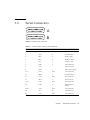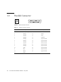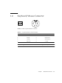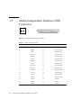
1
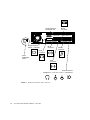
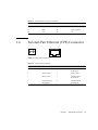
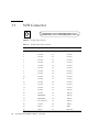
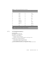
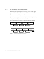
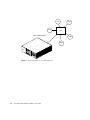
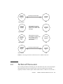
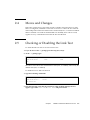
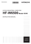
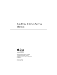
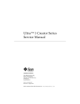
Sun Ultra 2 Series Reference
Manual
Sun Microsystems Computer Company
A Sun Microsystems, Inc. Business
901 San Antonio Road Palo Alto, CA 94303-4900 USA
650 960-1300
fax 650 969-9131
Part No.: 802-2562-11
Revision A, May 1996
1997 Sun Microsystems, Inc., 901 San Antonio Road, Palo Alto, California 94303-4900 U.S.A.
All rights reserved.
This product or document is protected by copyright and distributed under licenses restricting its use, copying, distribution, and decompilation.
No part of this product or document may be reproduced in any form by any means without prior written authorization of Sun and its licensors,
if any.
Portions of this product may be derived from the UNIX® system, licensed from Novell, Inc., and from the Berkeley 4.3 BSD system, licensed
from the University of California. UNIX is a registered trademark in the United States and in other countries and is exclusively licensed by
X/Open Company Ltd. Third-party software, including font technology in this product, is protected by copyright and licensed from Sun’s
suppliers. RESTRICTED RIGHTS: Use, duplication, or disclosure by the U.S. Government is subject to restrictions of FAR 52.227-14(g)(2)(6/87)
and FAR 52.227-19(6/87), or DFAR 252.227-7015(b)(6/95) and DFAR 227.7202-3(a).
Sun, Sun Microsystems, the Sun logo, and Solaris are trademarks or registered trademarks of Sun Microsystems, Inc. in the United States and in
other countries. All SPARC trademarks are used under license and are trademarks or registered trademarks of SPARC International, Inc. in the
United States and in other countries. Products bearing SPARC trademarks are based upon an architecture developed by Sun Microsystems, Inc.
The OPEN LOOK® and Sun™ Graphical User Interfaces were developed by Sun Microsystems, Inc. for its users and licensees. Sun
acknowledges the pioneering efforts of Xerox Corporation in researching and developing the concept of visual or graphical user interfaces for
the computer industry. Sun holds a nonexclusive license from Xerox to the Xerox Graphical User Interface, which license also covers Sun’s
licensees who implement OPEN LOOK GUIs and otherwise comply with Sun’s written license agreements.
THIS PUBLICATION IS PROVIDED “AS IS” WITHOUT WARRANTY OF ANY KIND, EITHER EXPRESS OR IMPLIED, INCLUDING, BUT
NOT LIMITED TO, THE IMPLIED WARRANTIES OF MERCHANTABILITY, FITNESS FOR A PARTICULAR PURPOSE, OR NONINFRINGEMENT.
Copyright 1997 Sun Microsystems, Inc., 901 San Antonio Road, Palo Alto, Californie 94303-4900 U.S.A. Tous droits réservés.
Ce produit ou document est protégé par un copyright et distribué avec des licences qui en restreignent l’utilisation, la copie et la décompilation.
Aucune partie de ce produit ou de sa documentation associée ne peut être reproduite sous aucune forme, par quelque moyen que ce soit, sans
l’autorisation préalable et écrite de Sun et de ses bailleurs de licence, s’il y en a.
Des parties de ce produit pourront être derivées du système UNIX® licencié par Novell, Inc. et du système Berkeley 4.3 BSD licencié par
l’Université de Californie. UNIX est une marque enregistrée aux Etats-Unis et dans d’autres pays, et licenciée exclusivement par X/Open
Company Ltd. Le logiciel détenu par des tiers, et qui comprend la technologie relative aux polices de caractères, est protégé par un copyright et
licencié par des fournisseurs de Sun.
Sun, Sun Microsystems, le logo Sun, et Solaris sont des marques déposées ou enregistrées de Sun Microsystems, Inc. aux Etats-Unis et dans
d’autres pays. Toutes les marques SPARC, utilisées sous licence, sont des marques déposées ou enregistrées de SPARC International, Inc. aux
Etats-Unis et dans d’autres pays. Les produits portant les marques SPARC sont basés sur une architecture développée par Sun Microsystems,
Inc.
Les utilisateurs d’interfaces graphiques OPEN LOOK® et Sun™ ont été développés de Sun Microsystems, Inc. pour ses utilisateurs et licenciés.
Sun reconnaît les efforts de pionniers de Xerox Corporation pour la recherche et le développement du concept des interfaces d’utilisation
visuelle ou graphique pour l’industrie de l’informatique. Sun détient une licence non exclusive de Xerox sur l’interface d’utilisation graphique,
cette licence couvrant aussi les licenciés de Sun qui mettent en place les utilisateurs d’interfaces graphiques OPEN LOOK et qui en outre se
conforment aux licences écrites de Sun.
CETTE PUBLICATION EST FOURNIE "EN L’ETAT" SANS GARANTIE D’AUCUNE SORTE, NI EXPRESSE NI IMPLICITE, Y COMPRIS, ET
SANS QUE CETTE LISTE NE SOIT LIMITATIVE, DES GARANTIES CONCERNANT LA VALEUR MARCHANDE, L’APTITUDE DES
PRODUITS A REPONDRE A UNE UTILISATION PARTICULIERE OU LE FAIT QU’ILS NE SOIENT PAS CONTREFAISANTS DE PRODUITS
DE TIERS.
Please
Recycle
Contents
Preface
ix
How This Book Is Organized x
Using UNIX Commands x
Typographic Conventions xi
Shell Prompts xi
Related Books xiii
Sun Documentation on the Web xiii
Sun Welcomes Your Comments xiii
1.
Back Panel Connectors
1-1
1.1
Connector Layout
1-1
1.2
Serial Connectors
1-3
1.3
Parallel Connector
1.4
Keyboard/Mouse Connector
1.5
Media Independent Interface (MII) Connector
1.6
Twisted-Pair Ethernet (TPE) Connector
1.7
SCSI Connector
1.8
1-4
1-5
1-7
1-8
1.7.1
SCSI Implementation
1.7.2
SCSI Cabling and Configuration
Audio Ports
1-6
1-9
1-10
1-11
iii
2.
3.
4.
5.
iv
1.9
Audio Specifications
1-12
1.10
Graphics Card 13W3 Video Connector
1-13
10BASE-T Twisted-Pair
Ethernet Link Test 2-1
2.1
Overview
2-1
2.2
Technical Discussion
2.3
Troubleshooting
2.4
Moves and Changes
2.5
Checking or Disabling the Link Test
2.6
Enabling the Link Test
2-6
Modem Setup Specifications
3-1
3.1
Setting Up the Modem
3-1
3.2
Serial Port Speed Change
3.3
Recommendations
2-3
2-4
2-5
2-5
3-2
3-2
3.3.1
Cable
3-2
3.3.2
Modem Switch Settings (AT Commands)
Main Logic Board Jumpers
4.1
Identifying Jumpers
4.2
Flash PROM Jumpers
4.3
Serial Port Jumpers
System Specifications
4-1
4-3
4-3
4-4
5-1
5.1
Power
5-1
5.2
Environment
5.3
Physical Specifications
5.4
Memory Mapping
5-2
5-3
Sun Ultra 2 Series Reference Manual • May 1996
5-3
3-3
Figures
FIGURE P-1
Ultra 2 Series Nameplates
FIGURE P-2
Ultra Enterprise 2 Nameplate
FIGURE 1-1
Back Panel Switches and Connectors
FIGURE 1-2
DB-25 Serial Connectors 1-3
FIGURE 1-3
DB-25 Parallel Connector 1-4
FIGURE 1-4
DIN-8 Keyboard/Mouse Connector 1-5
FIGURE 1-5
40-Pin Miniature-D MII Connector
FIGURE 1-6
RJ-45 TPE Connector
FIGURE 1-7
68-Pin SCSI Connector
FIGURE 1-8
Connecting External Mass Storage Devices
FIGURE 1-9
Audio Port Locations 1-11
FIGURE 1-10
13W3 Video Connector 1-13
FIGURE 2-1
Hosts and Hub in a Local Area Network 2-2
FIGURE 2-2
Ensuring Host-Hub Communication in a 10BASE-T Network 2-3
FIGURE 4-1
Jumper Locations on the Main Logic Board 4-2
FIGURE 4-2
Identifying Jumper Pins
ix
x
1-2
1-6
1-7
1-8
1-10
4-3
v
vi
Sun Ultra 2 Series Reference Manual • May 1996
Tables
TABLE P-1
Typographic Conventions xi
TABLE P-2
Shell Prompts
xi
TABLE P-3
Related Books
xiii
TABLE 1-1
Serial Connector Pinouts, RS-423/RS-232
TABLE 1-2
Parallel Connector Pinouts 1-4
TABLE 1-3
Keyboard/Mouse Connector Pinouts
TABLE 1-4
MII Connector Pinouts
TABLE 1-5
TPE Connector Pinouts 1-7
TABLE 1-6
68-Pin SCSI Connector Pinout 1-8
TABLE 1-7
Audio Port Signals 1-11
TABLE 1-8
Audio Port Functions
TABLE 1-9
Audio Inputs and Output
TABLE 1-10
Internal Monaural Speaker Specifications 1-12
TABLE 1-11
13W3 Video Connector Pinouts
TABLE 4-1
Flash PROM Jumper Settings 4-4
TABLE 4-2
Serial Port Jumper Settings
TABLE 5-1
Power Specifications
TABLE 5-2
Environmental Specifications (Operating)
TABLE 5-3
Environmental Specifications (Nonoperating)
TABLE 5-4
Dimensions and Weight 5-3
1-3
1-5
1-6
1-11
1-12
1-13
4-4
5-1
5-2
5-2
vii
viii
TABLE 5-5
Physical Clearances 5-3
TABLE 5-6
Main Logic Board Memory Mapping
Sun Ultra 2 Series Reference Manual • May 1996
5-3
Preface
The Sun Ultra 2 Series Reference Manual contains useful information about the use
and maintenance of a Sun™ Ultra™ 2 Series system.
This book is for use with Ultra 2, Ultra 2 Creator, Ultra 2 Creator 3D, and Ultra
Enterprise 2 systems only.
The nameplate on your system front panel must be like the nameplate(s) shown in
FIGURE P-1 or FIGURE P-2.
FIGURE P-1
Ultra 2 Series Nameplates
ix
FIGURE P-2
Ultra Enterprise 2 Nameplate
How This Book Is Organized
Chapter 1 provides the location of each back panel connector and gives the pinouts
for each connector.
Chapter 2 presents a full tutorial about connecting the system to a 10BASE-T
twisted-pair Ethernet (TPE} local area network (LAN).
Chapter 3 gives modem settings for Sun Ultra 2 Series systems used in specific
network telecommunication applications.
Chapter 4 gives the locations and pin definitions of user-configurable main-logic
board jumpers.
Chapter 5 gives system requirements about power and environment, and also gives
system dimension, weight, and memory mapping specifications.
Using UNIX Commands
This document may not contain information on basic UNIX® commands and
procedures such as shutting down the system, booting the system, and configuring
devices.
x
Sun Ultra 2 Series Reference Manual • May 1996
See one or more of the following for this information:
■
■
■
Solaris 2.x Handbook for SMCC Peripherals (If you are incorporating Solaris 2.x software
commands in your document, delete this sentence.)
AnswerBook™ online documentation for the Solaris™ 2.x software environment
Other software documentation that you received with your system
Typographic Conventions
TABLE P-1
Typographic Conventions
Typeface or
Symbol
Meaning
Examples
AaBbCc123
The names of commands, files,
and directories; on-screen
computer output.
Edit your .login file.
Use ls -a to list all files.
% You have mail.
AaBbCc123
What you type, when
contrasted with on-screen
computer output.
% su
Password:
AaBbCc123
Book titles, new words or
terms, words to be emphasized.
Command-line variable;
replace with a real name or
value.
Read Chapter 6 in the User’s Guide.
These are called class options.
You must be root to do this.
To delete a file, type rm filename.
Shell Prompts
TABLE P-2
Shell Prompts
Shell
Prompt
C shell
machine_name%
xi
TABLE P-2
xii
Shell Prompts
Shell
Prompt
C shell superuser
machine_name#
Bourne shell and Korn shell
$
Bourne shell and Korn shell superuser
#
Sun Ultra 2 Series Reference Manual • May 1996
Related Books
The following documents contain topics that relate to the information in the Sun
Ultra 2 Series Reference Manual.
TABLE P-3
Related Books
Application
Title
Part Number
Installation
Sun Ultra 2 Series Hardware Setup Instructions
802-5933
Installation
Sun Ultra 2 Series Installation Guide
802-5934
Service
Sun Ultra 2 Series Service Manual
802-2561
Sun Documentation on the Web
The docs.sun.com web site enables you to access Sun technical documentation on
the World Wide Web. You can browse the docs.sun.com archive or search for a
specific book title or subject at:
http://docs.sun.com.
Sun Welcomes Your Comments
We are interested in improving our documentation and welcome your comments
and suggestions. You can email your comments to us at:
[email protected].
Please include the part number of your document in the subject line of your email.
xiii
xiv
Sun Ultra 2 Series Reference Manual • May 1996
CHAPTER
1
Back Panel Connectors
1.1
Connector Layout
See the following figure.
1-1
Serial Connectors
RS-423/RS-232
Keyboard/
Mouse
Connector
SBus Slots 1, 0
SBus Slots 3, 2
UPA Slot
Graphics/Video
Output — UPA Slot
MII
Connector
Parallel
Connector
SCSI
Connector
Power
On/Standby
Switch
TPE
Connector
Audio Connectors
Headphones — Line Out — Line In — Microphone
FIGURE 1-1
1-2
Back Panel Switches and Connectors
Sun Ultra 2 Series Reference Manual • May 1996
1.2
Serial Connectors
13
1
25
14
13
1
25
14
A
B
FIGURE 1-2
DB-25 Serial Connectors
TABLE 1-1
Serial Connector Pinouts, RS-423/RS-232
Pin
Function
I/O
Signal Description
1
none
none
Not connected
2
TxD
O
Transmit Data
3
RxD
I
Receive Data
4
RTS
O
Ready To Send
5
CTS
I
Clear To Send
6
DSR
I
Data Set Ready
7
Gnd
8
DCD
I
Data Carrier Detect
9-14
none
none
Not connected
15
TRxC
I
Transmit Clock
16
none
none
Not connected
17
RTxC
I
Receive Clock
18-19
none
none
Not connected
20
DTR
O
Data Terminal
Ready
21-23
none
none
Not connected
24
TxC
O
Transmit Clock
25
none
none
Not connected
Signal Ground
Chapter 1
Back Panel Connectors
1-3
1.3
Parallel Connector
13
1
25
1-4
FIGURE 1-3
DB-25 Parallel Connector
TABLE 1-2
Parallel Connector Pinouts
14
Pin
Description
Pin
Description
1
Data_Strobe_L
14
nAutoFd
2
Data[1]
15
nFault
3
Data[2]
16
nInit
4
Data[3]
17
nSelectln
5
Data[4]
18
Signal Ground
6
Data[5]
19
Signal Ground
7
Data[6]
20
Signal Ground
8
Data[7]
21
Signal Ground
9
Data[8]
22
Signal Ground
10
nAck
23
Signal Ground
11
Busy
24
Signal Ground
12
PError
25
Signal Ground
13
Select
Sun Ultra 2 Series Reference Manual • May 1996
1.4
Keyboard/Mouse Connector
7
8
5
6
4
2
3
1
FIGURE 1-4
DIN-8 Keyboard/Mouse Connector
TABLE 1-3
Keyboard/Mouse Connector Pinouts
Pin
Description
Pin
Description
1
Ground
5
Keyboard Out
2
Ground
6
Keyboard In
3
+5 VDC
7
Power Key In
4
Mouse In
8
+5 VDC
Note – All signals are standard TTL levels. The +5V supply is fuse-protected.
Chapter 1
Back Panel Connectors
1-5
1.5
1-6
Media Independent Interface (MII)
Connector
20
1
40
21
FIGURE 1-5
40-Pin Miniature-D MII Connector
TABLE 1-4
MII Connector Pinouts
Pin
Function
Pin
Function
1
+5V
21
+5V
2
MDIO
22
Signal Ground
3
MDC
23
Signal Ground
4
RXD<3>
24
Signal Ground
5
RXD<2>
25
Signal Ground
6
RXD<1>
26
Signal Ground
7
RXD<0>
27
Signal Ground
8
RX_DV
28
Signal Ground
9
RX_CLK
29
Signal Ground
10
RX_ER
30
Signal Ground
11
TX_ER
31
Signal Ground
12
TX_CLK
32
Signal Ground
13
TX_EN
33
Signal Ground
14
TXD<0>
34
Signal Ground
15
TXD<1>
35
Ground
16
TXD<2>
36
Ground
17
TXD<3>
37
Ground
Sun Ultra 2 Series Reference Manual • May 1996
TABLE 1-4
1.6
MII Connector Pinouts (Continued)
Pin
Function
Pin
Function
18
COL
38
Signal Ground
19
CRS
39
Signal Ground
20
+5V
40
+5V
Twisted-Pair Ethernet (TPE) Connector
8
FIGURE 1-6
RJ-45 TPE Connector
TABLE 1-5
TPE Connector Pinouts
1
Pin
Description
Pin
Description
1
Transmit Data +
5
Common Mode
Termination
2
Transmit Data -
6
Receive Data -
3
Receive Data +
7
Common Mode
Termination
4
Common Mode
Termination
8
Common Mode
Termination
Chapter 1
Back Panel Connectors
1-7
1.7
SCSI Connector
34
68
1-8
FIGURE 1-7
68-Pin SCSI Connector
TABLE 1-6
68-Pin SCSI Connector Pinout
1
35
Pin
Signal Name
Pin
Signal Name
1
Ground
21
Ground
2
Ground
22
Ground
3
Ground
23
Ground
4
Ground
24
Ground
5
Ground
25
Ground
6
Ground
26
Ground
7
Ground
27
Ground
8
Ground
28
Ground
9
Ground
29
Ground
10
Ground
30
Ground
11
Ground
31
Ground
12
Ground
32
Ground
13
Ground
33
Ground
14
Ground
34
Ground
15
Ground
35
-DB<12>
16
Ground
36
-DB<13>
17
TERMPWR
37
-DB<14>
18
TERMPWR
38
-DB<15>
19
Not connected
39
-PAR<1>
20
Ground
40
-DB<0>
41
-DB<1>
63
-REQ
42
-DB<2>
53
Reserved
Sun Ultra 2 Series Reference Manual • May 1996
TABLE 1-6
68-Pin SCSI Connector Pinout (Continued)
Pin
Signal Name
Pin
Signal Name
43
-DB<3>
54
Ground
44
-DB<4>
55
-ATN
45
-DB<5>
56
Ground
46
-DB<6>
57
-BSY
47
-DB<7>
58
-ACK
48
-PAR<0>
59
-RST
49
Ground
60
-MSG
50
TERM.DIS
64
-IO
51
TERMPWR
65
-DB<8>
52
TERMPWR
66
-DB<9>
61
-SEL
67
-DB<10>
62
-CD
68
-DB<11>
Note – All signals shown in
1.7.1
TABLE 1-6 are active low.
SCSI Implementation
■
■
■
■
Single-ended
16-bit (wide SCSI) with parity
20 MBytes/sec Fast Wide SCSI
Supports 16 SCSI addresses:
Target 0-6 and 8-F for devices
Target 7 reserved for SCSI host adapter on main-logic board
Supports up to 3 internal SCSI drives:
■
■
■
SCSI disk drive target 0 (lower drive slot)
SCSI disk drive target 1 (upper drive slot)
■
SCSI CD-ROM drive target 6 or SCSI tape drive target 5
External 8-bit and 16-bit SCSI devices supported via 68-pin SCSI connector
■
■
■
Chapter 1
Back Panel Connectors
1-9
1.7.2
SCSI Cabling and Configuration
When mixing 8-bit and 16-bit SCSI devices on the same physical SCSI bus, follow
these cabling and configuration guidelines to insure proper device addressing and
operation:
■
If all external mass storage devices use 68-pin connectors, connect all non-Sun
devices to the Ultra 2 Series system first and follow them with Sun devices. Sun
devices use autotermination.
■
If external mass storage devices consist of 68-pin Sun devices and 50-pin devices,
connect the Sun 68-pin devices to the Ultra 2 Series system first and terminate the
daisy chain with the 50-pin device and its terminator.
See the following figure for a summary of cabling and configuration guidelines.
Ultra 2
series
Non-Sun
device
68—68
Non-Sun
device
Sun
device
68—68
68—68
68—68
Ultra 2
series
Sun
device
Sun
device
50-pin
device
68—50
68—68
Terminator
Adapter cable
FIGURE 1-8
1-10
Connecting External Mass Storage Devices
Sun Ultra 2 Series Reference Manual • May 1996
T
1.8
Audio Ports
Audio Ports:
Headphones — Line Out — Line In — Microphone
FIGURE 1-9
Audio Port Locations
All audio ports use EIA standard 3.5-mm (0.125-inch) jacks.
TABLE 1-7
Audio Port Signals
Headphones
Line Out
Line In
Microphone
Tip
Left Channel
Left Channel
Left Channel
Left Channel
Ring (Center)
Right Channel
Right Channel
Right Channel
Right Channel
Shield
Ground
Ground
Ground
Ground
TABLE 1-8
Audio Port Functions
Port
Function
Headphones
Connects stereophonic headphones for private listening of audio
output
Line Out
Connects the system audio output to an external stereophonic
amplifier and loudspeakers
Line In
Connects external stereophonic audio sources such as a compact
disc player or cassette tape player to the system
Microphone
Connects the SunMicrophone II (or other suitable microphone1) to
the system
Chapter 1
Back Panel Connectors
1-11
1. The Ultra 2 Series microphone port accepts stereophonic input; however, the Sun Microphone II is a monophonic device. Note also that the older SunMicrophone is not compatible with the Ultra 2 Series system.
1.9
Audio Specifications
The specifications in the following table assume use of the Audio Tool format setting
“CD-ROM or DAT” selected. TABLE 1-10 lists the internal monaural speaker
specifications.
The microphone input specifications are for the SunMicrophone II.
TABLE 1-9
Audio Inputs and Output
Stereo I/Os
Specifications
Line In
2V typical, 4V max.; 5-50-ohm impedance
Frequency Response
20 Hz-17 kHz +/- 0.5 dB
Internal CD Input
Input Level
0.1 percent Vrms typical at 10 kohms;
2Vpp max.
Distortion
0.01 percent, typical at 1 kHz
S/N Ratio
84 dB, typical IEC 179 A-weighted
Frequency
Response
20 Hz-17 kHz +/- 0.5 dB
Microphone Input
15 mV typical, 0.6-1.0 kohm impedance;
+5 VDC input bias via a 2.2 kohms resistor
Headphones Output
1V typical, 2.4V max.; 16 kohms to 1 kohm impedance
Line Out
1V typical, 2.4V max.; 5-50 kohms impedance
TABLE 1-10
1-12
Internal Monaural Speaker Specifications
Speaker
Specifications
Power Output
1.5W ave., 3W peak
Distortion
0.02 percent typical at 1 kHz
Impedance
16 ohms +/- 20 percent
Frequency Response
150 Hz-17 kHz +/- 0.5 dB
Sun Ultra 2 Series Reference Manual • May 1996
1.10
Graphics Card 13W3 Video Connector
1
5
A1 6
FIGURE 1-10
10 A2
A3
13W3 Video Connector
The graphics card for your system provides the 13W3 video connector for
transmitting video output signals from the system unit to the monitor.
See the following table for 13W3 video connector pinouts.
TABLE 1-11
13W3 Video Connector Pinouts
Pin
Function
I/O
Level
A1
Red
O
Analog
A2
Green
O
Analog
A3
Blue
O
Analog
1
Serial Read
2
Vert Sync
O
TTL
3
Sense <0>
I
TTL
4
Ground
5
Comp Sync
O
TTL
6
Horiz Sync
O
TTL
7
Serial Write
8
Sense <1>
I
TTL
9
Sense <2>
I
TTL
10
Ground
TTL
GND
TTL
GND
Chapter 1
Back Panel Connectors
1-13
1-14
Sun Ultra 2 Series Reference Manual • May 1996
CHAPTER
2
10BASE-T Twisted-Pair
Ethernet Link Test
Read this chapter if you are connecting your Ultra 2 Series system to a 10BASE-T
twisted-pair Ethernet (TPE) network. This chapter contains important information
for getting your system to communicate correctly over a TPE network. If you have
no experience with TPE networks, ask your system or network administrator to
perform the procedures in this chapter.
Note – This chapter does not apply to 100BASE-T networks. In such networks, the
link test function must be enabled at both the host and the hub. If your host is
connected to a 100BASE-T network, you must not disable the host link test function.
2.1
Overview
■
■
■
The twisted-pair Ethernet link integrity test is a function defined by the IEEE
802.3 10BASE-T specification.
For a networked workstation (host) to communicate with a network hub, the link
test state (enabled or disabled) must be the same on the host and hub.
If either the host or hub does not share the link test enabled/disabled state of the
other, then the host cannot communicate effectively with the hub, and the hub
cannot communicate effectively with the host.
The following figure gives an example of a star configuration local area network
(LAN), showing the relationship of hosts to a hub.
FIGURE 2-2 shows the importance of ensuring that the host and hub link test settings
match in a 10BASE-T network.
2-1
Host
Host
Host
Hub
Ultra 2 Series (Host)
Host
Host
FIGURE 2-1
2-2
Hosts and Hub in a Local Area Network
Sun Ultra 2 Series Reference Manual • May 1996
Link Test
Enabled
(Default)
1
Two-Way Communication
Hub
Ultra 2 Series
Link Test
Enabled
(Default)
1
Ultra 2 Series may boot
successfully, but with “lost
carrier” or “no carrier” error
messages.
Ultra 2 Series may boot
successfully, but other hosts
in the network cannot
communicate with the
Ultra 2 Series.
Two-Way Communication
Ultra 2 Series
FIGURE 2-2
2.2
Link Test
Enabled
1
Hub
Ultra 2 Series
Link Test
Disabled
(Reset)
0
Link Test
Disabled
0
Hub
Ultra 2 Series
Link Test
Disabled
(Reset)
0
Link Test
Enabled
1
Link Test
Disabled
0
Hub
Ensuring Host-Hub Communication in a 10BASE-T Network
Technical Discussion
The twisted-pair Ethernet link integrity test determines the state of the twisted-pair
cable link between the host and the hub in a network. Both the host and hub
regularly transmit a link test pulse. When either the host or hub has not received a
Chapter 2
10BASE-T Twisted-Pair Ethernet Link Test
2-3
link test pulse within a certain amount of time (50-150 ms), it makes the transition
from the link-pass state to the link-fail state and remains in the link-fail state until it
once again receives regular link test pulses.
The link integrity test is specific to twisted-pair Ethernet and is not applicable to the
other physical layer implementations of IEEE 802.3 such as 10BASE5 (”thicknet”) or
10BASE2 (“thinnet”).
The link test function at the host or hub is either enabled (link test enabled or 1) or
disabled (link test disabled or 0). The IEEE 802.3 10BASE-T specification requires
that the link test be enabled at both the host and the hub.
Although link test disabled does not conform to the specification, it is often
encountered in real-world 10BASE-T network installations. Some hubs from various
vendors can exhibit any of the following:
2.3
■
Link test is “hardwired” enabled—link test is always enabled.
■
Link test is “hardwired” disabled—link test is always disabled.
■
Link test is configurable—the network administrator may enable or disable link
test.
Troubleshooting
If you have connected an Ultra 2 Series host to a hub using twisted-pair Ethernet
cable and observe either “no carrier” messages or fail to communicate effectively
with another host in the same network, look first at the hub. If it supports
configurable link test, then make sure “link test enabled” is configured. This is
usually done by setting a hardware switch.
If the hub does not support configurable link test, then refer to the hub
manufacturer’s documentation. Check to see if your hub is hardwired for link test
disabled. If it is, you must follow the “Checking or Disabling the Link Test”
procedure elsewhere in this chapter to disable the link test at your Ultra 2 Series
host.
2-4
Sun Ultra 2 Series Reference Manual • May 1996
2.4
Moves and Changes
If the Ultra 2 Series host is physically moved to another network location or if the
hub is reconfigured, remember to refer back to FIGURE 2-2. Unless the new network
relationship between the host and the hub is functional (that is, 1-1 link test enabledlink test enabled or 0-0 link test disabled-link test disabled), there will be no full,
regular two-way communication between the host and the hub.
2.5
Checking or Disabling the Link Test
To check the link test state of an Ultra 2 Series host:
1. If you do not see the ok prompt, press the Stop (L1)-a keys.
2. At the ok prompt, type:
ok printenv tpe-link-test?
tpe-link-test?
true
ok
true
The above screen shows the current link test state (true, or enabled), followed by the
default state (true, or enabled).
To disable the host’s link test function:
1. Type the following commands:
ok setenv tpe-link-test? false
tpe-link-test? =
false
ok reset-all
2. Boot the host and verify that the transceiver cable problem messages do not
appear. Type either boot net or boot disk and press Return.
Chapter 2
10BASE-T Twisted-Pair Ethernet Link Test
2-5
2.6
Enabling the Link Test
1. If you do not see the ok prompt, press the Stop (L1)-a keys.
2. At the ok prompt, type:
ok printenv tpe-link-test?
tpe-link-test?
false
ok
true
The above screen shows the current link test state (false, or disabled), followed by
the default state (true, or enabled).
1. To enable the host’s link test function, type the following commands:
ok setenv tpe-link-test? true
tpe-link-test? =
true
ok reset-all
2. Boot the host and verify that the transceiver cable problem messages do not
appear. Type either boot net or boot disk and press Return.
2-6
Sun Ultra 2 Series Reference Manual • May 1996
CHAPTER
3
Modem Setup Specifications
3.1
Setting Up the Modem
Any modem compatible with U.S. Robotics‘ or CCITT V.24 can be connected to the
Ultra 2 Series serial ports. Modems can be set up to function in one of three ways:
■
■
■
Dial out only
Dial in only
Bidirectional Calls
To set up your modem:
1. Become superuser. Type admintool.
% su
Password:
# admintool
2. Highlight Browse.
3. Select Serial Port.
4. Select Port A or Port B for your modem connection.
5. Select Edit.
6. Select Expert.
7. Open the Use Template menu, and select one of the following:
Modem - Dial-Out Only
Modem - Dial-In Only
Modem - Bidirectional
3-1
8. Select Apply.
9. Set your modem auto-answer switch to one of the following:
For Dial-Out Only, set the switch to Off.
For Dial-In Only, set the switch to On.
For Bidirectional, set the switch to On.
3.2
Serial Port Speed Change
You must edit the /etc/remote file to change the speed of a serial port.
1. Become rootsuperuser, and type cd /etc.
% su
Password:
# cd /etc
2. Type vi remote.
3. Type tip speed
device-name.
Typical speeds are 9600, 19200 to 38400 bps.
The device name is the serial port name — for example,
/dev/tty[a,b] or /dev/term/[a,b].
4. Press Esc and type :wq to save your file change(s) and to exit from the vi text
editor.
3.3
Recommendations
3.3.1
Cable
For a modem-to-host (system) connection, use an RS-423/RS-232 straight-through
cable with DB-25 male connectors at both ends.
3-2
Sun Ultra 2 Series Reference Manual • May 1996
3.3.2
Modem Switch Settings (AT Commands)
■
■
Enable transmit flow control (AT&H1) [suggested setting]
(Required for sending binary/8-bit data)
Set link rate to fixed
(Will not track modem data rate, AT&Bn; n = menu choice in modem manual.)
■
Set display result codes (ATQ0)
■
Set verbal result codes (ATV1)
■
Set result code subset (ATXn; n = option choice)
■
Save settings in NVRAM (AT&W)
Note – The above settings are guidelines to help you get started quickly. Changes to
these guidelines should be expected depending on your site requirements and the
modem you are using.
For additional information about modem switch settings, see the manual that came
with your modem.
Chapter 3
Modem Setup Specifications
3-3
3-4
Sun Ultra 2 Series Reference Manual • May 1996
CHAPTER
4
Main Logic Board Jumpers
Jumper settings given in this chapter refer to etchings on the main logic board.
Jumpers are labeled with the letter “J” followed by a four-digit number.
See the following figure.
4-1
Back panel
J2901
Fan
DSIMM U slots:
0601,0701,0401,U0501
0602, 0702, 0402, 0502
0603, 0703, 0403, 0503
0604, 0704, 0404, 0504
Disk drive sd0
Disk drive sd1
Speaker
Front panel
FIGURE 4-1
4-2
Jumper Locations on the Main Logic Board
Sun Ultra 2 Series Reference Manual • May 1996
Disk drive 0 + 1
CPU 1
J2701
LOWER
J2801
UPA slot
CD-ROM drive
Diskette drive
CPU 0
Power
supply
UPPER
MIDDLE
SBus slot 3
J3002
J2502
J2105
SBus slot 1
J3102
J2501
Fan
J3201
J3001
SBus slot 2
SCSI
J3202
J3101
SBus slot 0
MII
J2104
Fan
Fan
Side panel
J2203
J2503
J2204
Audio ports
K/B
TPE
J2101 RJ45
NVRAM/TOD
Parallel port
4.1
Identifying Jumpers
Jumpers are marked on the main logic board with part numbers. For example, the
serial port jumpers are marked J2104 and J2105. Jumper pins are located
immediately adjacent to the part number. Pin 1 is marked with an asterisk in any of
the positions shown in the following figure.
J2XXX
Part number
Pins
*
*
*
*
*
FIGURE 4-2
4.2
*
Identifying Jumper Pins
Flash PROM Jumpers
The Ultra 2 Series system uses flash PROMs. Flash PROMs permit the following:
■
Reprogramming of specific code blocks
■
Remote reprogramming of the PROM chip by a system administrator over a local
area network
The default shunt setting of J2002 is on pins 1 and 2. This selects the flash PROM
chip as the controlling firmware device. See FIGURE 4-1.
The default shunt setting of J2003 is on pins 1 and 2. This disables the flash PROM
chip from being reprogrammed. Placing the shunt on pins 2 and 3 enables
reprogramming of the flash PROM chip.
Chapter 4
Main Logic Board Jumpers
4-3
Note – If you are reprogramming your system flash PROM, after successful
reprogramming be sure to return the flash PROM Write Protect/Enable jumper
(J2003) to the Write Protect position to increase system security.
TABLE 4-1
Flash PROM Jumper Settings
Jumper
Pins 1 + 2 Select
Pins 2 + 3 Select
Default Jumper
on Pins
J2002
Flash PROM
Not To Be Used
1+2
FLASH PROM
SEL
J2003
Write Protect
Write Enable
1+2
FLASH PROM
PROG ENABLE
J2204
High Half
Booting
Normal Booting
2+3
XOR LOGIC
SET
Signal Controlled
For flash PROM reprogramming information and the function of J2204, see the
SMCC System Flash PROM Programming Guide.
4.3
Serial Port Jumpers
The serial port jumpers on the main logic board permit configuring the two DB-25
serial ports on the system unit back panel for either RS-423 or RS-232 signal levels.
RS-423 levels are the default standard for North American users. RS-232 levels are
required for digital telecommunication in nations of the European Community.
TABLE 4-2
4-4
Serial Port Jumper Settings
Jumper
Pins 1 + 2 Select
Pins 2 + 3 Select
Default Jumper
on Pins
J2104
RS-232
RS-423
2+3
RS232/RS423
SEL
J2105
RS-232
RS-423
2+3
RS232/RS423
SEL
Sun Ultra 2 Series Reference Manual • May 1996
Signal Controlled
CHAPTER
5
System Specifications
5.1
Power
The following table lists power specifications.
TABLE 5-1
Power Specifications
Input/Output
Specifications
AC Power Input
100-240 VAC nominal, 47-63 Hz.
DC Power Output
350 W maximum
5-1
5.2
Environment
The following specifications comply with the International Electromechanical
Commission (IEC) Standards, 5th ed., 1990-1994.
TABLE 5-2
Environmental Specifications (Operating)
Operating
Altitude without
removable tape
media
0 meters (0 feet) [sea level], 40 degrees C (104 degrees F) to 3000
meters (9840 feet), 34.6 degrees C (94.2 degrees F)
— IEC 68-2-40
Altitude with
removable tape
media
0 meters (0 feet) [sea level], 35 degrees C (95 degrees F) to 3000
meters (9840 feet), 29.4 degrees C (84.9 degrees F)
— IEC 68-2-40
Humidity
5% to 95% relative humidity (RH) regardless of temperature
—IEC 68-2-02, 68-2-03
Shock
2.0G, 11 milliseconds, half sine pulse
— IEC 68-2-27
Vibration
0.1G, 5 to 500 Hz, swept sine — IEC 68-2-06
Temperature
5 degrees C to 40 degrees C
(41 degrees F to 104 degrees F)
— IEC 68-2-01, 68-2-02
TABLE 5-3
Environmental Specifications (Nonoperating)
Nonoperating
5-2
Altitude
0 to 12,000 meters (0 to 39,360 feet)
— IEC 68-2-40
Humidity
0% to 93% RH at 40 degrees C (104 degrees F)
— IEC 68-2-03
Shock
15 G peak, 11 milliseconds, half sine pulse
— IEC 68-2-27
Vibration
0.5 G, 5 to 500 Hz, swept sine — IEC 68-2-06
Temperature
20 degrees C to 55 degrees C
(-4 degrees F to 131 degres F)
— IEC 68-2-01, 68-2-0
Sun Ultra 2 Series Reference Manual • May 1996
5.3
Physical Specifications
TABLE 5-4
Dimensions and Weight
Height
Width
Depth
Weight
13.0 cm (5.12 in.)
45.0 cm (17.72 in.)
45.2 cm (17.94 in.)
15.88 kg (35.0 lb)
TABLE 5-5
Physical Clearances
Clearance
Specification
Compact Disc/Diskette
16.51 cm (6.5 in.)
System Unit Parallel Placement
7.6 cm (3.0 in.)1
1. Physical space between two system units side by side
5.4
Memory Mapping
Single in-line memory modules (SIMMs) are installed on the main logic board in
groups of four. Identical SIMMs are installed in each group.
TABLE 5-6
Main Logic Board Memory Mapping
Memory Group
Slots
0
U0501, U0701, U0401, U0601
1
U0502, U0702, U0402, U0602
2
U0503, U0703, U0403, U0603
3
U0504, U0704, U0404, U0604
Chapter 5
System Specifications
5-3
5-4
Sun Ultra 2 Series Reference Manual • May 1996