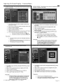
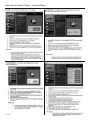
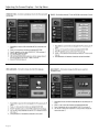
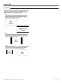
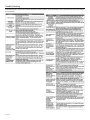
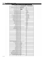
1
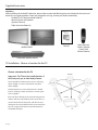
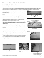
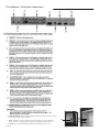
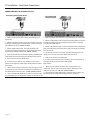
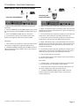
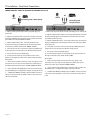
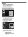
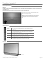
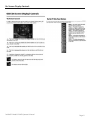
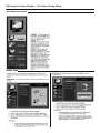
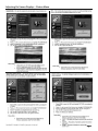
All-Weather Outdoor LCD Television
Operator’s Manual
Model 3220HD
Revision 3220-080326
Important Safety Instructions
Dear SunBriteTV Customer:
Congratulations on your ownership of the SunBriteTV Model 3220HD. This product is designed as a
weatherproof LCD television that can be installed outdoors. To ensure safety and minimize mechanical
malfunctions of your product, please read the Important Safety Instructions carefully before using this
product.
IMPORTANT SAFETY INSTRUCTIONS
1) Read these instructions.
2) Keep these instructions.
3) Heed all warnings.
4) Follow all instructions.
5) Do not block any ventilation openings. Install in accordance with the manufacturer’s instructions.
6) Do not install near any heat sources such as radiators, heat registers, stoves, or other apparatus (including amplifiers) that
produce heat.
7) Do not defeat the safety purpose of the polarized or grounding-type plug. A polarized plug has two blades with one wider than
the other. A grounding type plug has two blades and a third grounding prong. The wide blade or the third prong are provided for
your safety. If the provided plug does not fit into your outlet, consult an electrician for replacement of the obsolete outlet.
8) Protect the power cord from being walked on or pinched particularly at plugs, convenience receptacles, and the point where
the cord exits from the apparatus.
9) Only use attachements/acessories specified by the manufacturer.
10) Use only the cart, stand tripod, bracket, or table specified by the manufacturer, or
sold with the aparatus. When a cart is used, use caution when moving the cart/apparatus
combination to avoid injury from tip-over.
11) Unplug this apparatus during lightning storms or when unused for long
periods of time.
12) Refer all servicing to qualified service personnel. Servicing is required when the apparatus has been damaged in any way, such
as power-supply cord or plug is damaged, liquid has been spilled or objects have fallen into the apparatus, the apparatus has
been exposed to rain or moisture, does not operate normally, or has been dropped.
WARNING: TV must be plugged into a GFCI receptacle.
TV and GFCI RECEPTACLE MUST BE INSTALLED NO LESS THAN 5 FEET FROM ANY BODY OF
WATER (SUCH AS POOL OR SPA). Check local building codes for proper installation guidelines.
WARNING: This unit is equipped with a 3-pin grounded plug. The plug will only fit into a grounded power outlet. This is a safety
feature. If you are unable to insert the plug into the outlet, contact your electrician. Do not alter this plug, as this will defeat the
safety feature.
WARNING: The mains plug is used as the disconnect device and shall remain readily operable.
WARNING: This product shall be connected to a mains socket outlet with a protective earthing connection.
CAUTION: TO PREVENT ELECTRIC SHOCK, MATCH WIDE BLADE OF PLUG TO WIDE SLOT, FULLY INSERT.
WARNING: FCC Regulations state that any unauthorized changes or modifications to this equipment not expressly approved by
the manufacturer could void the user’s authority to operate this equipment.
NOTE TO CATV SYSTEM INSTALLER: This reminder is provided to call the CATV system installer’s attention to Article 820-40 of
the National Electrical Code that provides guidelines for proper grounding and, in particular, specifies that the cable ground shall
be connected to the grounding system of the building, as close to the point of cable entry as practical.
WARNING: To reduce the risk of fire or electric shock, do not expose the inside of this apparatus to rain or moisture.
The inside of this apparatus shall not be exposed to dripping or splashing, and no objects filled with liquids, such as vases, shall be
placed on the apparatus.
This product utilizes tin-lead solder, and fluorescent lamp containing a small amount of mercury. Disposal of these materials may be regulated due to environmental considerations. For disposal or recycling information, please contact your local
authorities or the Electronic Industries Alliance: www.eia.org.
Page 2
All Rights Reserved. 2008 ©SunBriteTV® LLC
Important Safety Instructions
Cleaning Instructions: Use a soft cloth with mild detergent in warm water to clean the SunBriteTV screen. Remove any dirt and
salt deposits from the unit, being careful to rinse the cloth frequently to avoid scratching the screen surface. Avoid using harsh
chemicals, abrasives, or solvents when cleaning any surface on the screen. Use a soft brush or towel to remove snow and ice from
the TV. In areas where dust or salt air is prevalent, it is recommended that the fiber filter be cleaned regularly (see instructions on
Page 41).
Attachments: Do not use attachments not specifically recommended by the manufacturer. Use of improper attachments can
result in accidents.
Power Source: SunBriteTV must operate on a power source indicated on the specification label. If you are not sure of the type of
power supply used in your home, consult your dealer or local power company. When using the TV outdoors, you must use a GFIprotected AC outlet with “in-use” waterproof cover.
Installation: Do not place the product on an unstable cart, stand, tripod, table, or anywhere the unit is not permanently installed.
Placing the product on an unstable place can cause the product to fall, resulting in potential serious personal injuries, as well as
damage to the product.
Precautions when Transporting the TV: Carrying the television requires at least two people.
FCC Statement
This equipment complies with the limits for a Class B
digital device, pursuant to part 15 of the FCC Rules.
These limits are designed to provide reasonable
protection against harmful interference in a
residential installation. This equipment generates,
uses, and can radiate radio frequency energy
and, if not installed and used in accordance with
the instructions, may cause harmful interference
to radio communications. However, there is no
guarantee that interference will not occur in a
particular installation. If this equipment does cause
harmful interference to radio or television reception,
which can be determined by turning the equipment
off and on, the user is encouraged to try to correct
the interference by one or more of the following
measures:
1. Reorient or relocate the receiving antenna.
2. Increase the separation between the equipment
and receiver.
3. Connect the equipment into an outlet on a
circuit different from that to which the receiver is
connected.
4. Consult the dealer or an experienced radio/TV
technician for help.
Modifications not expressly approved by the
manufacturer could void the user’s authority to
operate the equipment under FCC rules. This device
complies with part 15 of the FCC Rules. Operation is
subject to the following two conditions:
1. This device may not cause harmful interference.
2. This device must accept any interference received,
including interference that may cause undesired
operation.
SunBriteTV Model 3220HD Operator’s Manual
Page 3
Important Safety Instructions
Ventilation: Adequate ventilation must be maintained to ensure reliable and continued operation and to protect
the television from overheating. Do not block ventilation slots and openings with objects, or install the television in
a place where ventilation may be hindered. SunBriteTV is not designed for built-in installation. Do not place the
product in an enclosed place such as bookcase or rack.
Power cord protection: The power cord must be routed properly to prevent people from stepping on it, or objects
from resting on it. Check the cords at the plugs and product.
Power source: This product must operate on a power source specified on the specification label. If you are unsure of
the type of power supply used in your home, consult your dealer or local power company.
Do not let metal pieces or objects of any kind fall into the television from ventilation holes. High voltage flows in the
product, and inserting an object can cause electric shock and/or short internal parts.
Do not mount SunBriteTV near a motor or transformer where strong magnetism is generated. Images on the
television will become distorted and the color irregular.
Do not mount SunBriteTV near heat sources such as radiators, heaters, stoves and other heat-generating products
(including amplifiers).
Do not submerge SunBriteTV in water: The SunBriteTV will resist water exposure from normal rain, sprinklers,
garden hoses, etc.; however, it is not designed to be submerged in water.
Do not pressure-wash SunBriteTV: SunBriteTV will resist water exposure from normal rain, sprinklers, garden hoses,
etc.; however, it is not designed to withstand pressure washers, high-pressure water jets, or hurricane-type weather.
Do not service SunBriteTV yourself: Removal of the television screen cover may expose you to high voltage or other
dangerous risks. Refer all servicing to a qualified service professional. Warranty will not be honored if you service the
unit yourself.
Repair: If any of the following conditions occurs, unplug the power cord, and call a qualified service professional to
perform repairs:
When power cord or plug is damaged.
When objects have fallen into the product.
If unit was submerged in water or pressure-washed.
When product does not operate properly as described in the operating instructions. Do not touch the controls other
than as described in the operating instructions. Improper adjustments of controls not described in the
instructions can cause damage, which can require extensive repair work by a qualified technician.
When the product has been dropped or damaged.
When the product displays an abnormal condition. Any noticeable abnormality in the product indicates that the
product needs servicing.
Replacement parts: In case the product needs replacement parts, make sure that the service person uses
replacement parts provided by SunBriteTV. Use of unauthorized parts can result in fire, electric shock and/or other
danger.
Safety checks: Upon completion of service or repair work, ask the service technician to perform safety checks to
ensure that the product is in proper operating condition.
Page 4
Table of Contents
Important Safety Instructions
2
Table of Contents
5
Supplied Accessories
6
TV Installation
Choose a Location for the TV
6
Detachable Speaker Module Installation
7
Table Top Stand Instructions
8
Rear Panel Internal Connect Source
9
Rear Panel Connections
10
IR Emitter Window
11
Starting the TV
18
Side Panel Controls and Front Panel
19
Remote Control Guide
20
On-Screen Display Controls
21
On-Screen Display Menu
22
Adjusting On-Screen Displays
Channel Menu
22
Picture Menu
24
Sound Menu
26
Function Menu
28
Set-up Menu
31
Information Banner
34
Aspect Ratio
35
Ratings
36
Closed Caption
37
Trouble Shooting
38
Care of SunBriteTV
39
Specifications
40
PC Timing Codes
40
Features Information and Instructions
Internal Thermostatically-Controlled Heater
41
Programming Other Manufacturers’ Universal Remote Control Devices
41
SunBriteTV Pixel Quality Policy
41
Appendix A - RS232 Control Codes
SunBriteTV Model 3220HD Operator’s Manual
42
Page 5
Supplied Accessories
Unpacking
After unpacking the SunBriteTV television, please make sure that the following items are included in the carton and
that they are in good condition. If items are damaged or missing, contact your dealer immediately.
SunBriteTV LCD Television Model 3220HD
Remote Control with Batteries
Operator’s Manual
Table Stand Installation Kit
Operator’s
Manual
Model 3220HD
Detachable Speaker Module
TV Installation - Choose a Location for the TV
Choose a Location for the TV
Important: The TV must be installed at least 5
feet from pool, spa, or other body of water.
The TV should be installed so the screen is not facing
direct sunlight, or can be easily turned away from
direct sunlight.
Ideal placement is in an area where the TV is shaded
by trees, landscape and/or structures, or under a patio
cover or gazebo.
If the sun shines directly on the screen for long periods
of time, dark areas may develop on the screen. This is a
normal reaction for the LCD panel, and will not cause
damage to the screen. Either turn the screen away from
the sun, or apply shade to the TV, and the dark areas
will quickly disappear.
Page 6
Water-Resistant
Wireless Remote
Control with
Lithium Batteries
TV Installation - Detachable Speaker Module Installation
Detatchable Speaker Module Installation
Tools Needed: Phillips screwdriver
Note:
a. If you mount the TV on the Table Stand, the Detachable Speaker Module must be installed before you attach the Table Stand.
b. If you mount the TV to a ceiling or wall mount, it is best to install the Detachable Speaker Module after the TV has been
mounted.
Figure 1
1. Prepare a flat work surface, free of any debris or items which may scratch the
front surface of the TV.
2. Lay the TV face-down on the work surface with the bottom of the unit closest
to you
WARNING: Use at least two people when transporting the TV.
Pan Head Screws
3. Position the TV so that the bottom edge overhangs the table by about one
inch.
4. On the bottom rim of the TV, there are four Pan Head Mounting Screws.
Remove the Pan Head Mounting Screws, and set aside.
Important Note: Always replace mounting screws. Failure to do so will
allow water to seep inside your TV. This can cause serious injury and can
damage your TV.
Figure 2
TV and Speaker Module
Mounting Holes
5. Turn the Speaker Module with the speaker grill facing the floor. Align the
Speaker Mounting Holes to the TV Mounting Holes, and replace Pan Head
Mounting Screws through Speaker Mounting Holes and TV Mounting Holes.
(Figure 2).
Speaker Module
6. Screw securely (Figure 3).
7. Unscrew the three Thumb Screws, and pull the Connect Source Cover open
(Figure 4).
Figure 3
8. Take the Speaker Cable from the speaker, making sure that the Speaker Cable
Wire is placed over the right side of the Rubber Sealing Gasket (Figure 5), and
plug it into the Speaker Connector.
10. When you close the Connect Source Cover, be sure that the Speaker Cable
Wire is placed across the outside portion of the Rubber Sealing Gasket. The
Speaker Cable Wire should not be placed across the bottom of the Rubber
Sealing Gasket (Figure 6).
Figure 4
Thumb Screws
Connect Source Cover
Figure 5 Speaker Connector
Rubber Sealing
Gasket
Figure 6
Speaker Cable
Speaker Cable Wire should
not come out of this area
SunBriteTV Model 3220HD Operator’s Manual
Page 7
TV Installation – Rear Panel Internal Connect Source
WARNING: Do not connect the power source before making connections.
Internal Connect Source
The Internal Connect Source allows you to easily connect to the Audio, Video, S-Video, SVGA, HDMI, Audio Out, and RF connectors.
The Internal Connect Source is inside the Cable Cover located on the back of the unit (Figure1).
1. Unscrew the two gray Thumb Screws (Figure1), and pull the cover towards you.
2. Route the cables to the proper inputs, and place the cable cords over the Rubber Sealing Gasket (Figure 2).
3. Close the cover.
4. Press firmly on the cover, and screw the Thumb Screws tightly (Figure3).
Rubber Sealing Gasket
Figure 1
Thumb Screws
Figure 2
need new photo here
Figure 3
Page 9
SunBriteTV
Model 3220HD Operator’s Manual
Page 9
TV Installation – Rear Panel Connections
12. IR EMITTER WINDOW - The Internal Infrared (IR) Control Window allows the TV to be controlled
from a remote system using IR commands.
13. RS232 - The RS232 connection allows the TV to be controlled from a remote system using
RS232 commands. (See Appendix A of this manual for a list of RS232 control commands.)
14. 12 VDC - This port is for the SunBriteTV FM Radio (Item SB-FM322) connector only.
Page 10
11
12
13
14
TV Installation – Rear Panel Connections
IR Emitter Window:
Figure 15 shows an Emitter* installed. One end of the Emitter is to be mounted in
front of the IR Emitter Window. The other end is to be connected to an appropriate
control block*.
* Neither the emitter or control block are supplied by SunBriteTV. See instructions
that come with your IR Emitter and control block to determine how to make the
connection.
Important note: SunBriteTV recommends using a high-output IR Emitter, such as
Xantech 282M.
IR Emitter placed over the IR Window
Cable end that will be attached to an
external control block is routed over the
Rubber Sealing Gasket of the Internal
Connect Source. See proper Internal
Connect Source instructions on Page 9.
Figure 15
Connection Descriptions:
Cable Descriptions:
Red
Green
Blue
Yellow
Green
Red
White
SunBriteTV Model 3220HD Operator’s Manual
Page 11
TV Installation – Rear Panel Connections
Switching Sources for Ports:
Modeol 3220HD offers several options when connecting
your devices to the TV. The chart below will help you
understand which source you switch to for each of the
ports.
CONNECTING TO AN ANTENNA
Connecting to Digital Cable without Cable Box or Antenna
Connecting to Cable or Antenna
1. Make sure the power to the TV is turned off.
1. Make sure the power of the TV is turned off.
2. Connect the Coaxial RF cable from your
antenna or digital cable to the ATSC/NTSC port off
the back of your the TV.
2. Connect the Coaxial RF cable from your
antenna or cable to the
ATSC/NTSC port off the back of your TV.
3. Turn on the TV.
3. Turn on the TV.
4. Select TV (Air) for antenna or TV (Cable) for
digital cable from either your remote control’s
source button or source button on the right side
of the TV.
4. Select TV (Air) for antenna or TV (Cable) for
cable from either your remote control’s source
button or source button on the right side of the
TV.
5. Use the On-Screen Display to scan for channels.
5. Use the On Screen Display to scan for channels.
Please Note :
1. Not all broadcasts are in High Definition (HD). Please refer to your local broadcasting stations for more information.
2. The TV’s tuner is designed for HDTV therefore requires a stronger signal than normal TVs. If you cannot achieve that
signal level with your antenna or cable, your TV might lose picture or sound.
Page 12
TV Installation – Rear Panel Connections
CONNECTING TO AN ANTENNA--(Continued)
Connecting to Cable or Antenna through VCR
1. Make sure the power of the TV is turned off.
Please Note :
2. Make sure there is an antenna or cable
connection to the VCR already.
1. Some VCRs must be turned On before its output will have
a signal to the TV. Please consult your VCR manual for further
reference.
3. Use a Coaxial RF cable and connect from your
VCR’s Antenna Out or Output to TV to the ATSC/
NTSC port off the back of your TV.
4. Turn on the TV.
5. Select TV (Air) for antenna or TV (Cable) for
digital cable from either your remote control’s
source button or source button on the TV.
6. Use the On-Screen Display to scan for channels.
2. Not all broadcasts are in High Definition (HD). Please refer to
your local broadcasting stations for more information.
3. The TV’s tuner is designed for HDTV therefore requires a
stronger signal than normal TVs. If you cannot achieve that signal
level with your antenna or cable, the TV might lose picture or
sound.
CONNECTING TO A DVD PLAYER
Connecting with
YPbPr (Better)
Connecting with HDMI (Best)
1. Make sure the power of the TV and your DVD player is
turned off.
2. Connect a HDMI cable to the HDMI port of your DVD
player and the other end to the HDMI port off the back of
your TV.
1. Make sure the power of TV and your DVD player is turned off.
2. Obtain a Component Cable. Connect the green color connector
to both your DVD player and Component 1’s green connector port
off the back of your TV.
3. Turn on the TV and your DVD player.
3. Connect the blue color connector to both your DVD player and
Component 1’s blue connector port off the back of your TV.
4. Use the remote control’s source button or the source
button on the TV to switch to HDMI.
4. Connect the red color connector to both your DVD player and
Component 1’s red connector port off the back of your TV.
Please Note :
Refer to the DVD player’s manual to make sure the DVD player
is configured to output correctly to the TV.
5. Obtain a RCA Audio Cable. Connect the white color connector
to both your DVD player and Component 1’s white connector port
off the back of your TV to the right side of your green, blue, red
component connection.
6. Connect the red color connector to both your DVD player and
Component 1’s red connector port off the back of your TV to the
right side of your green, blue, red component connection.
7. Turn on the TV and your DVD player.
8. Use the remote control’s source button or the source button on
the TV to switch to YPbPr1.
Please Note :
1. Refer to the DVD player’s manual to make sure the DVD player
is configured to output correctly to the TV.
SunBriteTV Model 3220HD Operator’s Manual
Page 13
TV Installation – Rear Panel Connections
CONNECTING TO A DVD PLAYER (Continued)
Connecting with S-Video (Good)
1. Make sure the power of the TV and your DVD player is
turned off.
2. Obtain an S-Video Cable. Connect the S-Video connector
to both your DVD player and Composite’s S-Video connector
port off the back of your MODEL 3220HD.
3. Obtain a RCA Audio Cable. Connect the white color
connector to both your DVD player and Composite’s white
connector port off the back of your MODEL 3220HD.
Connecting with
Composite (Fair)
1. Make sure the power of the TV and your DVD player is turned off.
2. Obtain a Yellow Video Cable. Connect the Yellow Video connector
to both your DVD player and Composite’s Yellow Video connector
port off the back of your TV.
3. Obtain a RCA Audio Cable. Connect the white color connector to
both your DVD player and Composite’s white connector port off the
back of your TV.
4. Connect the red color connector to both your DVD player and
4. Connect the red color connector to both your DVD player Composite’s red connector port off the back of your TV.
and Composite’s red connector port off the back of your TV. 5. Turn on the TV and your DVD player.
5. Turn on the TV and your DVD player.
6. Use the remote control’s source button or the source button on
6. Use the remote control’s source button or the source
button on the right side of the TV to switch to AV1 (S-Video).
Please Note :
1. Make sure the yellow connector in the same group is not
connected. You can only connect either the S-Video port or
the Yellow Video connector port. DO NOT CONNECT BOTH.
2. Please reference the DVD player’s manual as well, to make
sure the DVD player is configured to output correctly to the TV.
Page 14
the right side of the TV to switch to AV1 (CVBS).
Please Note :
1. Make sure the yellow connector in the same group is not
connected. You can only connect either the S-Video port or the
Yellow Connector port. DO NOT CONNECT BOTH.
2. Please reference the DVD player’s manual as well, to make sure
the DVD player is configured to output correctly to the TV.
TV Installation – Rear Panel Connections
CONNECTING TO A SATELLITE OR CABLE SET-TOP BOX
Connecting with HDMI (Best)
1. Make sure the power of the TV and your set-top box is
turned off.
2. Connect a HDMI cable to the HDMI output of your set-top
box and the other end to the HDMI port off the back of your
TV.
3. Turn on the MODEL 3220HD and your set-top box.
4. Use the remote control’s source button or the source
button on the right side of the TV to switch to HDMI.
Please Note :
1 Please refer to the set-top box’s manual, to make sure the
set- top box is configured to output correctly to the TV.
2 SunBriteTV’s MODEL 3220HD supports SONY’s universal
remote code. Please look up SONY’s codes in your universal
remote’s hand book.
Connecting with
Component (Better)
1. Make sure the power of TV and your set-top box is turned off.
2. Obtain a Component Cable. Connect the green color connector
to both your set-top box and Component 1’s green connector port
off the back of your TV.
3. Connect the blue color connector to both your set-top box and
Component 1’s blue connector port off the back of your TV.
4. Connect the red color connector to both your set-top box and
Component 1’s red connector port off the back of your TV.
5. Obtain a RCA Audio Cable. Connect the white color connector
to both your set-top box and Component 1’s white connector port
off the back of your TV to the right side of your green, blue, red
component connection.
6. Connect the red color connector to both your set-top box and
Component 1’s red connector port off the back of your TV to the
right side of your green, blue, red component connection.
7. Turn on the TV and your set-top box.
8. Use the remote control’s source button or the source button on
the TV to switch to YPbPr1.
Please Note :
1. If Component 1 is already occupied, please use Component 2
as your connection port and switch to source YPbPr2.
2. Please refer to the set-top box’s manual to make sure the settop box is configured to output correctly to the TV.
3. SunBriteTV’s MODEL 3220HD supports SONY’s universal
remote code. Please look up SONY’s codes in your universal
remote’s hand book.
SunBriteTV Model 3220HD Operator’s Manual
Page 15
TV Installation – Rear Panel Connections
CONNECTING TO A SATELLITE OR CABLE SET-TOP BOX (Continued)
Connecting with S-Video (Good)
1. Make sure the power of the TV and your DVD player is
turned off.
2. Obtain an S-Video Cable. Connect the S-Video connector
to both your DVD player and Composite’s S-Video connector
port off the back of your MODEL 3220HD.
3. Obtain a RCA Audio Cable. Connect the white color
connector to both your DVD player and Composite’s white
connector port off the back of your MODEL 3220HD.
4. Connect the red color connector to both your DVD player
and Composite’s red connector port off the back of your TV.
5. Turn on the TV and your DVD player.
6. Use the remote control’s source button or the source
button on the right side of the TV to switch to AV1 (S-Video).
Please Note :
1. Make sure the yellow connector in the same group is not
connected. You can only connect either the S-Video port or
the Yellow Video connector port. DO NOT CONNECT BOTH.
2. Please reference the DVD player’s manual as well, to make
sure the DVD player is configured to output correctly to the TV.
3. SunBriteTV’s MODEL 3220HD supports SONY’s universal
remote code. Please look up SONY’s codes in your universal
remote’s hand book.
Page 16
Connecting with
Composite (Fair)
1. Make sure the power of the TV and your DVD player is turned off.
2. Obtain a Yellow Video Cable. Connect the Yellow Video connector
to both your DVD player and Composite’s Yellow Video connector
port off the back of your TV.
3. Obtain a RCA Audio Cable. Connect the white color connector to
both your DVD player and Composite’s white connector port off the
back of your TV.
4. Connect the red color connector to both your DVD player and
Composite’s red connector port off the back of your TV.
5. Turn on the TV and your DVD player.
6. Use the remote control’s source button or the source button on
the right side of the TV to switch to AV1 (CVBS).
Please Note :
1. Make sure the yellow connector in the same group is not
connected. You can only connect either the S-Video port or the
Yellow Connector port. DO NOT CONNECT BOTH.
2. Please reference the DVD player’s manual as well, to make sure
the DVD player is configured to output correctly to the TV.
3. SunBriteTV’s MODEL 3220HD supports SONY’s universal remote
code. Please look up SONY’s codes in your universal remote’s hand
book.
TV Installation – Rear Panel Connections
Connecting with Coaxial SPDIF Digital (Best)
1. Make sure the power of the TV and your receiver is turned off.
2. Obtain a Coaxial SPDIF cable, connect it to your receiver’s
coaxial SPDIF digital input and the Coaxial SPDIF connection
on the LINE OUT port off the back of the TV.
3. Turn on the TV and your receiver.
Please Note :
1. If you want pure digital stream for your receiver to
decode, you must also configure the TV’s OSD Sound->Digital
Audio Out function. Make sure the option is on Bit Stream.
2. If your receiver is making static noises when receiving Bit
Stream, you must use the PCM option instead.
3. Refer to the receiver’s manual to make sure the receiver is
configured to receive signals correctly from the TV
CONNECTING TO A PC
1. Make sure the power of the TV and your PC is turned off.
2. Obtain a 15-pin D-Sub VGA cable, connect to the VGA output of
your PC and the other end to the VGA port off the back of your TV.
3. Obtain a 3.5 mm Mini-jack, connect to the audio out of your PC
and the other end to the VGA Stereo Input port.
4. Turn on the power of the TV and your PC.
5. Use the remote control’s source button or the source button the
TV to switch to VGA.
6. Change your PC resolution to 1360x768 at 60hz refresh rate.
7. Press MENU to use the OSD’s SETUP option.
8. Under the SETUP option select PC function.
9. Under PC function use AUTO ADJUST to adjust the screen, AUTO
COLOR to adjust the color and use PREF. RESOLUTION to select
1360x768 at 60hz.
Please Note :
1. For the best results, please set your PC resolution to
1360x768 at 60 Hz. Refer to the PC or graphic card’s manual for
further instructions on how to set your resolution and refresh rate.
2. Refer to your PC manual for video output requirements of the
video card.
3. The VGA port of the TV features a power saving mode which will
automatically turn off the TV if there is no signal provided for more
than 5 minutes.
SunBriteTV Model 3220HD Operator’s Manual
Page 17
TV Installation – Starting the TV
Page 18
TV Installation - Starting the TV
Connecting the Power Cord
WARNING:
TV AND GFCI RECPTACLE MUST BE INSTALLED AT LEAST 5 FEET AWAY FROM STANDING WATER , SUCH AS (BUT NOT LIMITED
TO) A POOL OR SPA.
Connect the power cord after you have made connections to your video equipment.
Connect the power cord to a GFCIprotected AC outlet
with “in-use” waterproof cover.
Warning: TV must be installed at least 5 feet away from
standing water, such as (but not limited to) a pool or
spa.
Side Panel Controls
Power
Turn on the TV by pressing the button once. Press the button again to
turn off the TV.
Input
This button switches between the different sources of the TV. When the
On-Screen Display (OSD) is active, this button acts as the enter button
and confirms the menu selection.
Menu
This button activates the OSD. If a sub-menu is active, pressing this
button will return selection to the previous menu level.
CH+/CH-
These buttons change the TV channel up or down. If the OSD is active,
these buttons function as up or down controls for the menu.
Vol+ /Vol-
These buttons increase or decrease the volume. If a sub-menu is active,
pressing these buttons will move the selection left or right.
Front Panel
IR Sensor
SunBriteTV Model 3220HD Operator’s Manual
Page 19
Remote Control Guide
POWER – Turns the TV on or off.
MUTE – Mutes the TV’s audio.
0~9 – Sets the channels.
Dash (-) – Inserts the dash for selecting digital channels directly.
R – Returns to the previous channel. GUIDE – Opens the current
digital channel information guide.
SOURCE – Cycles between different inputs of the TV.
–Selects and moves the item on screen.
also functions as channel up and down.
also functions as volume up and down.
acts as the Enter button for OSD menu and changing
channels in conjunction with number buttons.
MENU – Opens / Exits the TV menu.
EXIT – Exits the TV menu.
SLEEP – Sets the Sleep timer. ASPECT – Selects different screen
size.
ADD – Adds the current channel. FREEZE – Freezes the TV
picture. CC – Cycles between different closed captioning
modes.
DELETE – Deletes the current channel.
INFO – Shows the TV info.
MTS – Selects stereo, mono, or second audio programming.
FAVORITE – Cycles the favorite channels
PICTURE – Selects various preset picture settings
SOUND – Selects various preset sound settings
This remote control follows Sony’s TV remote codes with
discrete on/off and input select.
Discrete TV code is 10,000
About the Water-Resistant Remote Control
The SunBriteTV TM All-Weather Outdoor Remote Control Model SB-RC23-WR is a water-resistant remote control that runs on two
long-life lithium batteries. “Water-resistant” means that this remote control can be in water for short periods of time without
damaging the internal workings of the unit. It can be left in the rain, and even dropped in water, as long as it is retrieved quickly.
The remote control should not be left floating in water.
If the remote control is used properly, it will give you many years of service. The functionality of the remote control and the longlife lithium batteries are under warranty for one year.
If the remote control malfunctions or stops working within the one-year warranty period, SunBriteTV will repair or replace the
remote control at SunBriteTV’s option.
Do not attempt to replace the batteries yourself because the battery cover is sealed for water resistance. If the battery cover is
removed, the warranty will become void.
If you have a warranty claim, contact the SunBriteTV Customer Support Team for further instructions.
Page 20
On-Screen Display Controls
SunBriteTV Model 3220HD Operator’s Manual
Page 21
Adjusting On-Screen Displays – On-Screen Display Menu
ON-SCREEN DISPLAY MENU
CHANNEL MENU
Page 22
Adjusting On-Screen Displays – Channel Menu
SunBriteTV Model 3220HD Operator’s Manual
Page 23
Adjusting On-Screen Displays – Picture Menu
Picture Menu
Page 24
Adjusting On-Screen Displays – Picture Menu
SunBriteTV Model 3220HD Operator’s Manual
Page 25
Adjusting On-Screen Displays – Picture Menu
Sound Menu
Page 26
Adjusting On-Screen Displays – Sound Menu
SunBriteTV Model 3220HD Operator’s Manual
Page 27
Adjusting On-Screen Displays – Sound Menu
Function Menu
Page 28
Adjusting On-Screen Displays – Function Menu
SunBriteTV Model 3220HD Operator’s Manual
Page 29
Adjusting On-Screen Displays – Function Menu
Page 30
Adjusting On-Screen Displays – Function Menu
Set-Up Menu
SunBriteTV Model 3220HD Operator’s Manual
Page 31
Adjusting On-Screen Displays – Set-Up Menu
Page 32
Adjusting On-Screen Displays – Set-up Menu
SunBriteTV Model 3220HD Operator’s Manual
Page 33
Information Banner
Information Banner
Preset Modes
Page 34
Aspect Ratio
Aspect Ratio
SunBriteTV Model 3220HD Operator’s Manual
Page 35
Ratings
Ratings
Page 36
Closed Caption
Closed Caption
SunBriteTV Model 3220HD Operator’s Manual
Page 37
Trouble Shooting
The following table contains the common problems and the solutions to htese problems. Please check this list before you contact
the technicians.
Page 38
Care of SunBriteTV
Important Information About the Anti-Reflective Window on your SunBriteTV
Outdoor Television
The anti-reflective window on your all-weather TV is designed to dramatically reduce reflection and improve the contrast of
the image on your TV. In order to preserve the anti-reflective properties of the window, it is imperative that you follow the
maintenance guidelines below:
1. Clean the window by using the following directions:
To clean the SunBriteTV window, use an ammonia-free glass cleaner and a lint-free or micro-fiber cloth. Spray the solution on
the cloth and then apply to the window. DO NOT use acrylic cleaners or ammonia.
2. When the TV is not in use, keep it covered with the SunBriteTV Outdoor Dust Cover
The fitted dust cover is constructed with weatherproof 4-ply polypropylene UV protection fabric that protects the window
from direct and indirect sunlight, and keeps wind-blown objects from scratching the surface of the window.
To order the Dust Cover, contact your Authorized SunBriteTV dealer or SunBriteTV’s Customer Service at 866.357.8688.
General Cleaning
Remove any dirt and salt deposits from the unit, being careful to rinse the cloth frequently to avoid scratching the TV or screen
surface. Avoid using harsh chemicals, abrasives, or solvents when cleaning any surface on the unit.
Snow and Ice
Use a soft brush and towel to remove snow and ice from the unit.
Fiber Filters
The Fiber Filters are located on the back of the TV, inside the Intake Vent at the top of the TV (Figure 1). In areas where dust or salt air
is prevalent, it is recommended that the Fiber Filters be cleaned regularly.
1. Release the Fiber Filters by pulling them out from the corner of the Intake Vent (Figure 2). Notice how the Fiber Filters fit in the
upper and lower channels, and tightly against the angled corners (Figure 3).
2. Pull the Fiber Filters out of the TV, and wash them with mild detergent and warm water. After rinsing, let them dry completely.
3. Put the Fiber Filters back up into the Intake Vent pushing the filter first into the upper channel, then fit it into the lower channel.
Make sure the filters fits tightly against angled corners at each end of the Intake Vent.. (Figure 4).
Intake Vent
Figure 1
Figure 2
Fiber Filter
Fiber Filter
Figure 4
Figure 3
Upper Channel
Angled Corner
Lower Channel
Angled Corner
SunBriteTV Model 3220HD Operator’s Manual
Page 39
Specifications
Specifications
LCD Screen
31.5-inch diagonal TFT Active Matrix
Resolution
1366 x 768
Aspect Ratio
16:9
Contrast Ratio
1500:1
H/V Viewing Angle
178o by 178o
Response Time
8 milliseconds
TV formats
1080i, 720p, 480i, 480p
Input Connectors:
RF
Antenna/CATV (NTSC/ATSC/QAM)
HDMI
HDMI Input x2
Video Composite
S-Video x1 and Composite Video x1, L/R Audio Inputs x1
Video Component
YCbCr/YPbPr x2 and audio L/R channels x2
PC
15-pin D-sub VGA plus Stereo Audio
RS232 Serial
Full-featured command set with discrete on/off, input select
and volume control
Discrete IR Control
SunBriteTV Model 3220HD
(All dimensions are in inches)
Front View
TV Dimensions are:
32.066 in. W x 23.204 in. H x 6.287 in. D
Height dimension with table top stand is 23.458 in.
Codes for Power On/Off and Input Select
Input Power
100-240 VAC, 50-60 Hz 2.5A Max
Audio
8-watt x 2 channels, water-resistant speaker module
(detachable), SPDIF Audio output connector inside rear cover
Operating Temp.
-24o to 122o F. (-31o to 50o C.)
Non-op. Temp.
(Off-mode with
power applied)
-24o to 140o F. (-31o to 60o C.)
Accessories Included
Water-resistant remote control with lithium battery
R
TV Dimensions
32.07 in. W x 23.20 in. H x 6.29 in. D
Weight
37.5 lbs., 41.6 lbs w/speakers
Shipping Dimensions 37.0 in. W x 31.0 in. H x 11.7 in. D
Shipping Weight
54 lbs.
Warranty5XP-year, in-factory, parts and labor
Temperature range is for operation in shaded location
Under all conditions, the LCD TV should be installed in a shaded area where the screen is not facing direct sunlight (or placed/mounted where the TV
can easily be turned away from direct sunlight).
PC Timing Codes
Page 40
Side View
Features Information and Instructions
Internal Thermostatically-Controlled Heater
The Internal Thermostatically-Controlled Heater keeps the unit warm in freezing temperatures and activates automatically when the
SunBriteTV internal temperature sensor reads a temperature inside the unit of 32O F. or lower. The heater remains on until the internal
temperature rises to at least 42O F. The heater provides a 20O F. temperature rise, allowing the TV to safely remain in temperatures as low
as -24O F. The ventilation fans are not activated when the heater is running and will automatically activate when required.
If temperatures below -24O F. are expected, we recommend that you bring your SunBriteTV inside to prevent damage to the LCD screen.
Note: In order for the automatic heater to work properly, your SunBriteTV must have power applied at all times.
Programming Other Manufacturers’ Universal Remote Control Devices
When programming a DirectTV, local cable universal remote control or Control system, you may find that SunBriteTV may not be on the
list of TV manufacturers. If that is the case, Model 4610HD supports SONY’s universal remote code.
SunBriteTV Pixel Quality Policy
SunBriteTV’s Pixel Quality Policy
(Applicable to LCD TVs sold within USA and Canada only.)
SunBriteTV TM LCD screens are manufactured with rigorous standards to maintain optimal viewing. However, the LCD screen may
have minor defects that appear as a small bright or dark pixel. This is common to all LCD screens used in display and television
products, and is not specific to SunBriteTV.
Bright dots are dots that appear bright and unchanged in size when a LCD TV screen displays a black pattern.
Dark dots are dots that appear dark and unchanged in size when a LCD TV screen displays a pure red, green, or blue pattern.
Adjacent dots are pixels located directly next to each other.
Your SunBriteTV will be replaced under warranty if it meets one of the following criteria:
—A total of 7 defective pixels, including both bright dots and dark dots are present. (Model 4610HD LCD TV screen has over a million
pixels.)
—2 or more pairs of adjacent bright dots are present.
—3 adjacent bright dots are present.
—3 adjacent dark dots are present.
To locate defective pixels, the LCD panel should be examined under normal operating conditions, in its native display resolution,
with a 90 degree viewing angle, from a distance of a approximately 20 inches.
To qualify for replacement, a defective LCD screen must be reported to SunBriteTV within 14 days from the day the customer
receives the TV.
For questions, please call our toll-free service number at 866.357.8688.
SunBriteTV Model 3220HD Operator’s Manual
Page 41
Appendix - RS232 Control Codes
Page 42
SunBriteTV Model 3220HD Operator’s Manual
Page 43
www.sunbritetv.com
Page 44