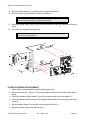
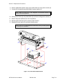
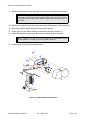
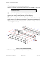
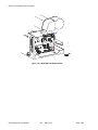
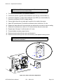
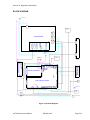
1
M10e
Thermal Transfer Printer
SERVICE MANUAL
PN 9001113A
SATO America, Inc.
10350A Nations Ford Road
Charlotte, NC 28273
Main Phone: (704)644-1650
Tech Support Hotline: (704)644-1660
Tech Support Fax: (707)644-1661
E-Mail: [email protected]
www.satoamerica.com
© Copyright 2003
SATO America, Inc.
All rights reserved. No part of this document may be reproduced or issued to third parties in any form
whatsoever without the express permission of SATO America, Inc. The materials in this document is
provided for general information and is subject to change without notice. SATO America, Inc. assumes no
responsibilities for any errors that may appear.
TABLE OF CONTENTS
INTRODUCTION
General Description
Theory Of Operation
Switches And Indicators
Connection Ports
1-2
1-2
1-4
1-6
TECHNICAL DATA
Physical Characteristics
Power
Enviromental
Print
Media
Ribbon
Sensing
Interface Modules
Processing
Character Font Capabilities
Barcode Capabilities
Regulatory Approvals
2-1
2-1
2-1
2-1
2-1
2-2
2-2
2-2
2-2
2-2
2-4
2-4
INTERFACE SPECIFICATIONS
Interface Types
Receive Buffer
IEEE1284 Parallel Interface
RS232 Serial Interface
Universal Serial Bus (USB) Adapter
Local Area Network (LAN) Interface
Bi-Directional Communications
3-1
3-1
3-2
3-4
3-6
3-6
3-7
ACCESSORIES INSTALLATION
Label Cutter
PCMCIA Memory Expansion
Real-time Clock
Interface Module Upgrade
Stacker Kit
Media Unwind Unit
4-1
4-3
4-3
4-5
4-5
4-5
CONFIGURATION
Dip Switch Panels
RS232 Transmit/Receive Setting
Printer Setup
Default Settings
Software Default Settings
Potentiometer Adjustments
LCD Panel Printer Configuration
5-1
5-1
5-3
5-7
5-7
5-8
5-9
PN 9001113A
TROUBLESHOOTING
Error Signals
Troubleshooting Table
RS232 Serial Interface Troubleshooting
Universal Serial Bus (USB) Interface Troubleshooting
Parallel Interface Troubleshooting
LAN Ethernet Interface Troubleshooting
TCP/IP Troubleshooting
Netware Troubleshooting
Windows NT/LAN Server Troubleshooting
Windows 95/98 Peer-To-Peer Troubleshooting
Diagnostic Label Printing
Print Buffer Hex Dump
Receive Buffer Hex Dump
TP Test Module Usage
Ribbon Sensor Operation Verification
6-1
6-2
6-5
6-5
6-6
6-7
6-8
6-9
6-10
6-11
6-11
6-11
6-11
6-12
6-13
REPLACEMENT PROCEDURES
Print Head
Roller Belt
Ribbon Belt
Platen Roller
Feed Roller
Main Circuit Board
Interface Board
Ribbon Drive Board
Memory Card
Panel Board
Power Board
Power Board Fuse
Circuit Board Fuse
Drive Motor
Ribbon Rewind Motor
Auto-Load Sensor
Label-Out Sensor
Label Position Sensor
Label Gap Sensor
Eye Mark Sensor
Ribbon Sensor
Cutter Assembly
Cutter Sensor
EEPROM Chip
7-1
7-2
7-3
7-4
7-6
7-7
7-8
7-9
7-11
7-11
7-12
7-14
7-15
7-16
7-17
7-19
7-20
7-20
7-20
7-21
7-23
7-24
7-26
7-27
PN:
9001113A
ADJUSTMENT PROCEDURES
Print Head Position
Print Head Balance
Ribbon Wrinkle
Roller Belt
Ribbon Belt
Paper Guide
Pitch Sensor
Eye-Mark Sensor
Label Gap Sensor
Auto-Load Sensor
Paper End Sensor
Offset Label Stop Position
LCD Display
Print Darkness
8-1
8-2
8-3
8-5
8-6
8-7
8-8
8-10
8-12
8-13
8-15
8-16
8-17
8-17
FACTORY RESETS
Factory Settings/Test Print
Clear Head Counters
Clear Cutter Counter
Clear EEPROM
9-1
9-2
9-3
9-4
DIAGRAMS & SCHEMATICS
Housing Cover Removal & Installation
Media & Ribbon Loading
Block Diagram
Printing Operational Sequence
Accessories & Sensors Location
Print Reference Position
PN 9001113A
10-1
10-2
10-3
10-4
10-5
10-6
PN:
9001113A
1
INTRODUCTION
This manual is laid out consistent with the product discussed and provides all of the information
required for general printer configuration, troubleshooting, and maintenance. For specialized
programming, refer to the Programming Manual located on the utility CD-ROM.
Step-by-step maintenance instructions are provided with typical problems and solutions. It is
recommended that you become familiar with each section before installing and maintaining the
printer.
This manual also incorporates the use of special information boxes. Examples of these boxes
and the type of information provided in each, are below.
WARNING: PROVIDES INFORMATION THAT, IF UNHEEDED, MAY
RESULT IN PRESONAL INJURY.
CAUTION: PROVIDES INFORMATION THAT, IF UNHEEDED, MAY
RESULT IN EQUIPMENT DAMAGE.
NOTE: Provides helpful hints to assist in performing the tasks at hand.
LCD DISPLAY: Provides the specific display that should be visible on the
LCD at that point.
A comprehensive Table Of Contents provided at the front of this manual facilitates rapid
movement within. The contents identify the different unit sections and their respective subsections. Each references the page number of their commencement.
The pages of this manual has embedded headers and footer to assist the user in identifying his
or her exact position within the manual. The header provides the section number followed by its
name. The footer identifies the product on the left, the manual’s part number in the center, and
the page number to the right side of the page.
Page inumeration is two-part with each separated by a hyphen. The first character set references
the section number and the second identifies the page number. Page numbers begin with the
numeral (1) one at the commencement of a new section and ascends sequentially.
SATO M10e Service Manual
PN:
9001113A
Page 1-1
Section 1: Introduction
GENERAL DESCRIPTION
The M-10e printer is a wide carriage thermal printer designed specifically to address the need for
large high resolution labels. It can print labels as large as 10.5 inches wide x 16.5 inches high
with a resolution of 305 dpi (dots per inch) at speeds up to 5 inches per second, making it ideal
for large compliance label applications. All printer parameters are user programmable using the
front panel controls and DIP switches. All popular bar codes and 14 human readable fonts,
including vector and two raster fonts, are resident in memory providing literally thousands of type
styles and sizes.
The M10e is available in two versions. The M10eDT is a direct thermal only version and must use
thermally sensitive paper to print. The M10eTT is a thermal transfer model and has provisions for
using a thermal transfer ribbon. It can also print in a direct thermal mode if the ribbon is not used.
The printer uses the standard SATO Printing Language command codes. The primary
differences between it and other SATO printers are the allowable values representing the print
positions on the label. These values are specified in “dots” and will vary depending upon the
resolution of the printer and the amount of memory available for imaging the label. The allowable
range is specified in the SATO “e” Printer Programming Reference. This commonality makes it
easy to convert labels from one SATO printer without having to create an entirely different
command stream. There are some caveats that must be observed though to compensate for the
different resolution print heads. The effects of the different print resolutions are best illustrated by
taking a label designed for a 305 dpi printer and sending the command stream to a 609 dpi
printer. The label printed will be an exact one half scale, including the fonts, bar code dimensions
and line length/widths. The only exceptions are the Postnet bar code and OCR-A and OCR-B
fonts that have only one legal size. Conversely, a label designed for a 609 dpi printer and sent to
its 305 dpi cousin will be twice as large. It probably will be “truncated” if the resulting size is larger
that the maximum allowable for the printer.
THEORY OF OPERATION
When activated, the media and ribbon (where applicable) are fed conjunctively past the print
head by an integrated drive train. The drive train is electric motor driven, coupled to a belt/pulley
configuration located on the right side of the printer chassis. Paper guides within the chassis
assembly ensure that the media remains properly positioned during the printing process and is
fed unimpeded through an opening in the front cover. The exhausted ribbon material is rewound
onto a take-up core inserted onto drive-train driven, spring loaded spindles.
A series of strategically located sensors sends signals to the processing unit. The processing unit
in turn sends response signals to the various features based on programmed and received data.
SATO M10e Service Manual
PN:
9001113A
Page 1-2
Section 1: Introduction
Correct signals initiates print head activity.
Access Cover
Width
Operator
Panel
Height
Display
Panel
Power Switch
Paper Exit
Depth
Figure 1-1, Front View
Ribbon Supply
Spindle
Empty Ribbon
Core
Head Release
Lever
Ribbon Rewind Spindle
Figure 1-2, Interior View
SATO M10e Service Manual
PN 9001113A
Page 1-3
Section 1: Introduction
SWITCHES AND INDICATORS
The table below identifies and defines printer switches and indicators for operator interface. The
accompanying graphics display their locations and appearance
Power Switch
Line Key
Feed Key
LCD Display
Power Indicator
Error
On-Line
DSW2 & DSW3
DSW1
SWITCHES
Two position on/off switch that controls power flow to the system.
Toggles the printer between the on-line and off-line modes. When
on-line, the printer is ready to recieve data from the host. Acts as a
pause during print by taking the printer off-line. Also used as a scroll
and enter interface for computer setup.
Feeds one blank label through the printer when off-line. When the
printer is on-line, another copy of the last label will be printed. Also
used as a scroll and enter interface for computer setup.
INDICATORS
Dual line x 16 character display. Used for setting operational parameters and displaying error conditions.
Illuminates when the power switch is activated.
Illuminates when there is a system fault.
Illuminates when the system is operating and ready to receive data.
DIP SWITCHES
Sets operational parameters of printer.
Used to configure optional RS232 communication card.
Power LED
On Line LED
Error LED
LCD Display
Line Key
Feed Key
Directional Keys
Enter Key
Figure 1-3, Front Panel
SATO M10e Service Manual
PN:
9001113A
Page 1-4
Section 1: Introduction
Dip Switches
Potentiometers
Figure 1-4, Configuration Panel
Configuration
Panel
Interface Port
External
Accessory Port
Media Paper
Guide Adjustment
Media Loaded
LED
AC Supply
Port
Memory Card
Port
Figure 1-5, Rear View
SATO M10e Service Manual
PN 9001113A
Page 1-5
Section 1: Introduction
CONNECTION PORTS
These ports are externally accessable and permit connection of the accessories and
attachments necessary for printer programming and operation. Not listed here, are the
connection ports of circuit boards not externally accessable.
AC Supply Port
Interface Port
Ext. Interface Port
Memory Card Slot
Main Fuse Connection
SATO M10e Service Manual
CONNECTION PORTS
Connector permits 115V, 50/60 Hz supply via supplied cord.
Connector for interface harness. Must be connected for the printer
to be operational. Optional interface types are :
• RS232C Serial I/F Module, DB-25
• IEEE1284 Parallel I/F Module, AMP 57-40360
• Universal Serial Bus I/F Module
• Ethernet 10/100 BaseT I/F Module, RJ-45
• RS422/485 I/F Module, DB-9
Connector for optional accessories - AMP 57-60140
Slot for the insertion of optional PCMCIA Memory Card
For input power protection - type 3A/250V
PN:
9001113A
Page 1-6
2
TECHNICAL DATA
All technical data deemed pertinent has been tabulated below for quick reference. Find the
relative section header and then locate the specific type of technical data in th left column.
PHYSICAL CHARACTERISTICS
Width
18.7 Inches (475 mm)
Height
12.6 Inches (320 mm)
Depth
12.3 Inches (314 mm)
Weight
50.7 Pounds (23 kg)
POWER
Input Voltage
Autoswitching 100-240 VAC +/- 10%, 60 Hz
Power Consumption
560 Watt Operating, 40 Watt Idle
ENVIRONMENTAL
Operating Temperature
41° to 104°F (5° to 40°C)
Storage Temperature
23° to 140°F (-5° to 60°C)
Storage Humidity
30 to 90% RH Non-Condensing
Operating Humidity
30 to 80% RH Non-Condensing
Electrostatic Discharge
PRINT
Method
Direct or Thermal Transfer
Speed (user selectable)
3 to 5 Inches Per Second (50 - 250 mm/s)
Print Module (dot size)
.0033 Inches (.083 mm)
Resolution
305 Dots Per Inch (12 d/mm)
Maximum Print Width
10.5 Inches (266 mm)
Maximum Print Length
16.5 Inches (420 mm)
MEDIA
Minimum Width
5.16 Inches (131 mm)
Minimum Length
1.7 Inches (43 mm)
Maximum Width
11.8 Inches (300 mm)
Type
SATO M10e Service Manual
Roll or Fan-Fold Die Cut, Thermally Sensitive for DT
PN:
9001113A
Page 2-1
Section 2: Technical Data
MEDIA
Maximum Caliper
.008 Inches (0.21 mm)
Maximum Roll Diameter
7.8 Inches (200 mm), Wound face inward
Minimum Core Diameter
3 Inches (76.2 mm)
RIBBON
Maximum Width
10.7 Inches (273 mm)
Length
984 Feet (300 m)
Thickness
4.5 Microns, Wound face inward
SENSING
See-Through
Fixed, 0.9 Inches (22.5 mm) left of center
Reflective Eye-Mark
Fixed, 0.2 Inches (5 mm) from left label edge.
Continuous Form
Sensor not used.
INTERFACE MODULES
Parallel Port
IEEE 1284 Standard
Serial Port
RS232C (9600 to 57,6000 dps) Standard
RS422/485 (9600 to 57600 bps) Optional
Ready/Busy or X-On/X-Off Flow Control
Bi-Directional Status
Universal Serial Bus
USB Version 1.1 Standard
Ethernet
10/100 Base T
PROCESSING
CPU
32 Bit RISC
FLash ROM
4 Mega-Bytes
SDRAM
16 Mega-Bytes
Receive Buffer
2.95 Mega-Bytes
Memory Expansion
See Options and Accessories
CHARACTER FONT CAPABILITIES
MATRIX FONTS
U Font
5 dots W x 9 dots H
S Font
8 dots W x 15 dots H
M Font
13 dots W x 20 dots H
XU Font
5 dots W x 9 dots H (Helvetica)
XS Font
17 dots W x 17 dots H (Univers Condensed Bold)
SATO M10e Service Manual
PN:
9001113A
Page 2-2
Section 2: Technical Data
CHARACTER FONT CAPABILITIES
MATRIX FONTS
XM Font
24 dots W x 24 dots H (Univers Condensed Bold)
OA Font (OCR-A)
22 dots W x 33 dots H
OB Font (OCR-B)
30 dots W x 36 dots H
AUTO SMOOTHING FONTS
WB
18 dots W x 30 dots H
WL
28 dots W x 52 dots H
XB
48 dots W x 48 dots H (Univers Condensed Bold)
XL
48 dots W x 48 dots H (Sans Serif)
VECTOR FONT
Proportional or Fixed Spacing
Font Size 50 x 50 dots to 999 x 999 dots
Helvetica, 10 Font Variations
AGFA RASTER FONTS
A Font
CG Times, 8 to 99 pt.
B Font
CG Triumvirate, 8 to 99 pt.
DOWNLAODABLE FONTS
Bit Mapped True Type Fonts with Utility Program
CHARACTER CONTROL
Expansion up to 12 x in either the X or Y coordinates.
Charcter Pitch Control
Line Space Control
Journal Print facility
0, 90, 180, and 270 Degree Rotation
SATO M10e Service Manual
PN 9001113A
Page 2-3
Section 2: Technical Data
BAR CODE CAPABILTIES
Linear Bar Codes
Bookland (UPC/EAN Supplemental
EAN-8, EAN-13
CODABAR
Code 39
Code 93
Code 128
Interleaved 2 of 5
Industrial 2 of 5
Matrix 2 of 5
MSI
POSTNET
UCC/EAN-128
UPC-A and UPC-E
Data Matrix
Maxicode
PDF417
Micro PDF
Truncated PDF
QR Code
Two Dimemsional
Ratios
1:2, 1:3, 2:5, User definable bar widths
Bar Height
4 to 999 dots, User progammable
Rotation
Sequential Numbering
0, 90, 180, and 270 Degrees
Sequential numbering of both numerics and bar codes
Custom Characters
Graphics
Form Overlay
RAM storage for special characters
Full dot addressable graphics, SATO Hex/Binary, .BMP or
.PCX formats
High-speed editing of complex predesigned formats in image
buffer
REGULATORY APPROVALS
Safety
UL, CSA, TUV
RFI/EMI
FCC (Class B)
SATO M10e Service Manual
PN:
9001113A
Page 2-4
INTERFACE SPECIFICATIONS
3
This section presents the interface specifications for the M10e printer. These specifications
include detailed information on how to properly interface the printer with the host system.
INTERFACE TYPES
To provide flexibility in communicating with a variety of host computer systems, all printers use a
Plug-In Interface Module. The IEEE1284 Interface module is shipped with the printer unless
another interface type is specified at the time of the order. The other interfaces available are a
high speed (to 57.6K bps) serial interface, an Ethernet interface or an optional Universal Serial
Bus (USB) interface.
The Parallel interface will probably be the most useful in communicating with IBM PCs and
compatibles. The RS232C Serial interface allows connectivity to a number of other hosts. The
USB interface allows the printer to be connected to a computer that supports peripherals
attached to a USB bus. Up to 127 peripherals can be connected to a single USB port. The
optional interfaces available are a high speed (to 57.6K bps) serial interface, an Ethernet
interface or a Universal Serial Bus (USB) interface.
WARNING: NEVER CONNECT OR DISCONNECT INTERFACE CABLES
(OR USE A SWITCH BOX) WITH POWER APPLIED TO EITHER THE
HOST OR THE PRINTER. THIS MAY CAUSE DAMAGE TO THE
INTERFACE CIRCUITRY IN THE PRINTER/HOST AND IS NOT COVERED
BY WARRANTY.
THE RECEIVE BUFFER
The printer may be configured to receive a data stream from a single or multiple print jobs. The
single job print buffer is generally used by software programs that wish to maintain control of the
job print queue so that it can move a high priority job in front of ones of lesser importance. The
multiple job buffer, on the other hand prints all jobs in the order they are received by the printer,
and the order of printing cannot be changed.
SINGLE JOB BUFFER
The printer receives and prints one job at a time. Each job must not exceed 2.95 MB.
MULTIPLE JOB BUFFER
The printer is able to continuously receive print jobs while compiling and printing other jobs at the
same time. It acts much like a “print buffer” to maximize the performance of the host and the
printer. When using the RS232C Serial interface, the multiple job buffer uses either the Ready/
Busy with DTR (pin 20) or X-On/X-Off flow control protocols. See these sections for more details.
SATO M10e Service Manual
PN:
9001113A
Page 3-1
Section 3: Interface Specifications
With an empty receiving buffer, the status of DTR is “high” (in X-On status if using X-On/X-Off)
meaning the printer is ready to receive data. When the receive buffer is holding 2.0 MB of data
(.95 MB from being full), DTR will go “low” (an X-Off is sent) indicating the printer can no longer
receive data. This condition is called “Buffer Near Full.”
The receiving buffer will not be able to receive more data again until a “Buffer Available” condition
occurs. This takes place when the receiving buffer has emptied so that only .95 MB bytes of data
are being held (2.0 MB bytes from being full). At this time, DTR will go “high” or an X-On is sent to
tell the host that it can again receive data.
All printer error conditions (i.e., label out, ribbon out) will cause the printer to go busy (DTR “low”
or X-Off) until the problem is corrected and the printer is placed on-line. The printer will also be
busy if taken off-line from the front panel.
IEEE1284 PARALLEL INTERFACE
The parallel interface is a Plug-In Interface Module that can be installed by the user. The
interface automatically detects the IEEE1284 signals and operates in the high speed mode. If
signals are not detected, it will operate in the slower standard Centronics mode. For this reason,
an interface cable and host interface conforming to the IEEE1284 specification must be present
to fully utilize the speed capabilities. This interface also operates bi-directionally and can report
the status of the printer back to the host.
SATO M10e Service Manual
PN:
9001113A
Page 3-2
Section 3: Interface Specifications
SPECIFICATIONS
Printer Connector
Cable Connector
Cable
Signal Level
Data Stream
AMP 57-40360 DDK (or equivalent)
AMP 57-30360 DDK (or equivalent)
IEEE1284 Parallel, 10 ft. (3 m) or less
High = +2.4V to +5.0V, Low = 0V to -0.4V
<ESC>A . . Job#1 . . <ESC>Z<ESC>A . . Job#n . . <ESC>Z
NOTE: Pin assignments begin with one (1) in the upper right corner and
descend to eighteen (18) in the upper left corner. Pin number nineteen (19)
picks up in the lower right corner and descends to thirty-six (36) in the lower
left.
IEEE 1284 PARALLEL INTERFACE PIN ASSIGNMENTS
PIN
SIGNAL
DIRECTION
1 Strobe
To Printer
2 Data 1
To Printer
3 Data 2
To Printer
4 Data 3
To Printer
5 Data 4
To Printer
6 Data 5
To Printer
7 Data 6
To Printer
8 Data 7
To Printer
9 Data 8
To Printer
10 ACK
To Host
11 Busy
To Host
12 Ptr Error
To Host
13 Select
To Host
14 AutoFD1
To Host
15 Not Used
16 Logic Gnd
17 FG
Frame Gnd
18 +5V (z=24k ohm) To Host
1 Signals required for ieee 1284 mode.
SATO M10e Service Manual
PIN
19
20
21
22
23
24
25
26
27
28
29
30
31
32
33
34
35
36
SIGNAL
Strobe Return
Data 1 Return
Data 2 Return
Data 3 Return
Data 4 Return
Data 5 Return
Data 6 Return
Data 7 Return
Data 8 Return
ACK Return
Busy Return
PE Return
INIT
Fault
Not Used
Not Used
Not Used
SelectIn1
PN 9001113A
DIRECTION
Reference
Reference
Reference
Reference
Reference
Reference
Reference
Reference
Reference
Reference
Reference
Reference
From Host
To Host
From Host
Page 3-3
Section 3: Interface Specifications
RS232 SERIAL INTERFACE
The High Speed Serial Interface is a Plug-In Interface Module that can be installed in the printer
by the user.
SPECIFICATIONS
Asynchronous ASCII
Half-duplex communication
Ready/Busy Hardware Flow Control
Pin 20, DTR Control
Pin 4, RTS Error Condition
X-On/X-Off Software Flow Control
Bi-Directional Communication
9600, 19200, 38400, 57600 bps
1 Start Bit (fixed)
7 or 8 data bits (selectable)
Odd, Even or No Parity (selectable)
1 or 2 Stop bits (selectable)
DB-25S (Female)
DB-25P (Male), 50 ft. maximum length.
For cable configuration, refer to Cable
Requirements appropriate to the RS232C protocol chosen.
High = +5V to +12V, Low = -5V to -12V
Data Transmission Rate
Character Format
Connector
Cable
Signal Levels
NOTE: Pin assignments begin with one (1) in the upper right corner and
descend to thirteen (13) in the upper left corner. Pin number fourteen (14)
picks up in the lower right corner and descends to twenty-five (25) in the
lower left.
RS232C SERIAL INTERFACE SIGNALS
PIN
DIRECTION
1
2
Reference
To Host
3
4
To Printer
To Host
5
To Printer
6
To Printer
7
Reference
SIGNAL DEFINITION
FG (Frame Ground)
TD (Transmit Data) - Data from the printer to the host computer. Sends X-On/
X-Off characters or status data (bi-directional protocols).
RD (Receive Data) - Dataa to the printer from the host computer.
RTS (Request to Send) - Used with Ready/Busy flow control to indicate an
error condition. RTS is high and remains high unless the print head is open (in
this case, RTS would return to the high state after the print head is closed and
the printer is placed back on-line) or an error condition occurs during printing
(e.g., ribbon out, label out).
CTS (Clear to Send) - When this line is high, the printer assumes that data is
ready to be transmitted. The printer will not receive data when this line is low. If
this line is not being used, it should be tied high (to pin 4).
DSR (Data Set Ready) - When this line is high, the printer will be ready to
receive data. This line must be high before data is transmitted. If this line is not
being used, it should be tied high (to pin 20).
SG (Signal Ground)
SATO M10e Service Manual
PN:
9001113A
Page 3-4
Section 3: Interface Specifications
RS232C SERIAL INTERFACE SIGNALS
PIN
20
DIRECTION
To Host
SIGNAL DEFINITION
DTR (Data Terminally Ready) - This signal applies to Ready/Busy flow control.
The printer is ready to receive data when this pin is high. It goes low when the
printer is off-line, either manually or due to an error condition, and while
printing in the single job buffer mode. It will also go low when the data in the
buffer reaches the buffer near full level.
CABLE REQUIREMENTS
DB9
DB25
HOST
DB25
PRINTER
1
1
FG (Frame Ground)
1
FG (Frame Ground)
2
3
RD (Receive Data)
2
TD (Transmit Data)
3
2
TD (Transmit Data)
3
RD (Receive Data)
8
5
CTS (Clear to Send)
4
RTS (Request to Send)
7
4
RTS (Request to Send)
5
CTS (Clear to Send)
4
20
DTR (Data Terminal Ready)
6
DSR (Data Set Ready)
6
6
DSR* (Data Terminal Ready)
20
DTR (Data Terminal Ready)
5
7
SG (Signal Ground)
7
SG (Signal Ground)
* This connection at the host side of the interface would depend upon the pin that is being used as the
Ready/Busy signal by the driving software. Typically, on a PC, it would be either CTS (pin5) or DSR (pin
6) on a DB-25 connector.
READY/BUSY FLOW CONTROL
Ready/Busy is the hardware flow control method for the serial interface on the M-84PRO
printers. By raising/lowering the voltage level on Pin 20 of the RS232C port, the printer notifies
the host when it is ready to receive data. Pin 4 (RTS) and pin 20 (DTR) are the important signals
on the printer for this method of flow control. The host must be capable of supporting this flow
control method for it to function properly.
X-ON/X-OFF FLOW CONTROL
X-On/X-Off flow control is used whenever hardware (Ready/Busy) flow control is not available or
desirable. Instead of a voltage going high/low at pin 20, control characters representing ìPrinter
Readyî (X-On =11 hexadecimal) or “Printer Busy” (X-Off = 13 hexadecimal) are transmitted by
the printer on pin 2 (Transmit Data) to the host. In order for this method of flow control to function
correctly, the host must be capable of supporting it. X-On/X-Off operates in a manner similar to
the function of pin 20 (DTR) as previously explained. When the printer is first powered on it sends
an X-Off when the “Buffer Near Full” level is reached and a X-On when the data level of the buffer
drops below the “Buffer Available” mark. When the printer is taken off-line manually, it transmits
an X-Off indicating it cannot accept data. When it is placed back on line manually, it sends an XOn, indicating it is again available for receipt of data. If an error occurs during printing (paper out,
ribbon out), the printer sends an X-Off as soon as an error condition is detected. When the error
is cleared and the printer is placed back on-line, it transmits an X-On indicating it is again ready
to accept data. Upon power up if no error conditions are present, the printer will continually send
X-On characters at five millisecond intervals until it receives a transmission from the host.
SATO M10e Service Manual
PN 9001113A
Page 3-5
Section 3: Interface Specifications
DATA STREAMS
The data streams for X-On/X-Off and Ready/Busy flow control are constructed in the same way
as they are for Ready/Busy flow control (<ESC>A . . Job#1 . . <ESC>Z<ESC>A . . Job#n . .
<ESC>Z). An example of this would be: <ESC>A . . Job#1 . . <ESC>Z. All characters are in
ASCII.
UNIVERSAL SERIAL BUS (USB) INTERFACE
The Universal Serial Bus (USB) interface is a Plug-In Interface Module that can be installed by
the user. It requires a driver (shipped with each printer that has the interface installed) that must
be loaded on your PC and the PC must be configured to support USB peripherals using Windows
98 or above. Details for loading the USB driver are contained in the USB Interface Manual that is
shipped with each printer with a USB Optional interface installed. Up to 127 devices may be
connected to a USB port using powered hubs.
SPECIFICATIONS
Printer Connector
Cable
Host
Power Supply
Power Consumption
USB Type B Plug
10 feet (3 m) maximum
Windows 98 or above with USB Port
BUS Power through cable
+5 V at 80 ma
LOCAL AREA NETWORK (LAN) OPTIONAL INTERFACE
A Local Area Network (LAN) interface is a Plug-In Interface Module that can be installed by the
user. It requires a driver shipped with each printer that has the interface installed. The driver
must be loaded on your PC and the PC must be configured to run one of the supported network
protocols using a 10/100BaseT LAN connection. Details for loading the LAN driver are contained
in the LAN Interface Manual that is shipped with each printer with a LAN Optional interface
installed.
SPECIFICATIONS
Connector
Cable
Power Supply
SATO M10e Service Manual
RJ-45 Receptacle
10/100BaseT Catagory 5
Powered from printer
PN:
9001113A
Page 3-6
Section 3: Interface Specifications
BI-DIRECTIONAL COMMUNICATIONS
This is a two-way communications protocol between the host computer and the printer, thus
enabling the host to check printer status. When Bi-Com 4 communications is selected, there is no
busy signal from the printer. The host must request the complete status from the printer, including
ready/busy. The host may request status in two different ways.
ENQUIRE/ACK/NAK
In the Bi-Com 4 mode, the host transmits an ENQ (05 hexadecimal) to the printer and the printer
will respond with its status within five milliseconds. If printing, it will respond upon finishing the
current label, then resume printing. In order for this protocol to work properly with an RS232C
Optional Interface, pin 6 (DTR) and pin 5 (CTS) must be held high by the host. One way to
ensure these pins are always in the correct state is to tie pin 20 (DTR) to pin 6 (DSR) and pin 4
(RTS) to pin 5 (CTS) at the printer end of the cable.
ENQUIRE (ENQ)
Upon receipt of an ENQ command, the printer responds with 25 bytes of status information
bounded by an STX/ETX pair. The Bi-Com protocol works only in the multiple job buffer mode.
The status information is defined as follows:
<STX>{ 2 Byte ID}{1 Status Byte}{6 Byte Label Remaining}{16 Byte Job Name}<ETX>
STREAM IDENTIFICATION
ID
Status
Label Remaining
Job Name
Is a two byte number identifying the current print job ID. The print
job ID is defined using the <ESC>ID Job ID command transmitted
with the print job (see Job ID Store in the command listing for
more information on how to use this command). The range is
from 00 to 99.
A single byte defining the current status of the printer (see the
Status Byte Definition table).
Six bytes defining the number of labels remaining in the current
print job. The range is from 000000 to 999999 labels.
16 bytes of ASCII characters identifying the name assigned to the
job by the <ESC>WK Job Name command. If the Job Name is
less than 16 characters, the field will be padded with leading
zeroes.
If an ENQ is received after the print job specified in the ID bytes
has been completed, or there is no data in the buffer, the printer
will respond with two “space” characters (20 hexadecimal) for the
ID number, six “zero” characters (30 hexadecimal) in the
Remaining Labels bytes and the 16 byte Job Name.
CANCEL (CAN)
If a CAN (18 hexadecimal) command is received , it will stop the print job and clear all data from
the receive and print buffers. A delay of five milliseconds or more is required before any new data
can be downloaded. The CAN command is effective immediately upon receipt, even if the printer
is off-line or in an error condition. The printer will return an ACK (06 hexadecimal) if there is no
printer error condition and a NAK (15 hexadecimal) if an error condition exists.
SATO M10e Service Manual
PN 9001113A
Page 3-7
Section 3: Interface Specifications
PRINT JOB
Upon receipt of a valid print job (<ESC>A . . . <ESC>Z), an ACK (06 hexadecimal) will be
returned by the printer if there are no errors and a NAK (16 hexadecimal) if a printer error exists.
PRINT STOP (DLE)
If a DLE (10 hexadecimal) is received by the printer, the print process is stopped and an ACK (06
hexadecimal) is returned if there are no errors and a NAK (16 hexadecimal) if a printer error
exists.
PRINT START (DC1)
If the printer has been stopped by receipt of a DLE (10 hexadecimal) command, it can be
restarted by sending a DC1 (hexadecimal 11) command. Upon receipt of this command an ACK
(06 hexadecimal) is returned if there are no errors and a NAK (16 hexadecimal) if a printer error
exists.
NOTE: To provide compatibility with older SATO printers, the RS232C
interface can be configured to use an earlier Bi-Com 3 ENQ/ACK/NAK
protocol selected via DSW2-8 and DSW1-7/8 (on the RS232 Interface
module).The earlier protocol did not have provisions for the Job Name and
did not respond to the DLE or DCI commands. Also, there are additional
Response Codes in the Status Byte Definition. It is recommended that you
use the current protocol rather than the earlier version unless it is necessary
for compatibility with existing software.
SATO M10e Service Manual
PN:
9001113A
Page 3-8
4
ACCESSORIES INSTALLATION
The following procedures provide in-depth instructions on the installation of all optional
accessories. Each accessory is a purchase option that may not apply to your setup. Refer to the
list below to determine if any are applicable and their installation is required. If not, disregard this
section of the manual and proceed to the next.
LABEL CUTTER INSTALLATION
This procedure only applies to the physical installaiton of cutter assembly hardware. Refer to
other procedures for configuration, etc.
1
Switch off the printer and disconnect the power supply cord.
2
Remove the top, front, left, and right housing covers.
NOTE: Figure 10-1 in the Diagrams & Schematics section provides guidance
on housing cover removal.
3
Remove three screws (1, Figure 4-1a) securing tear-off plate (2) to printer frame (3).
3
1
1
2
Figure 4-1a, Cutter Installation
SATO M10e Service Manual
PN:
9001113A
Page 4-1
Section 4: Accessories Installation
4
Lift away tear-off plate (2).
5
Place cutter assembly (4, Figure 4-1b) onto printer frame (3).
NOTE: When properly placed, the cutter motor should be oriented on the left
side of the printer and protrude behind the main circuit board.
6
Secure cutter assembly (4) to printer frame (3) using three screws (5).
NOTE: The cutter will be secured with two screws applied to the left end, and
one screw to the right. They will be appied in different orifices on the printer
frame than the dispenser.
7
Apply safety switch (6) to front housing cover (7) and secure using screw (8).
NOTE: When properly applied, the safety switch will be mounted to the
interior surface of the front housing cover oriented so that its mounting
orifices are aligned with the orifice in the cover and the mounting pin. The
switch will remain in the open position when mounted.
3
B
A
5
C
8
C
6
4
5
7
Figure 4-1b, Cutter Installation
8
Connect wiring harness (A) from the cutter motor to main board connector (CUTTER).
9
Connect wiring harness (B) from the cutter sensor to main board connector (CUTSEN).
10 Connect wiring harness (C) from the cutter internal switch to safety switch (6).
SATO M10e Service Manual
PN:
9001113A
Page 4-2
Section 4: Accessories Installation
NOTE: The wiring harness connectors and their mates on the main cicuit
board are unique to all others on the board. Properly couple the matching
connectors. Refer to Figure 10-4, Block Diagram of the Diagram &
Schematics section for greater detail if necessary.
11
Configure the printer for cutter accessory operation.
NOTE: Refer to the Configuration section of this manual or the Programming
Manual for label cutter configuartion instructions.
12
Apply media stock and ribbon as applicable and test cycle to ensure proper function.
13
Install the left, right, front, and top housing covers.
NOTE: Figure 10-1 in the Diagrams & Schematics section provides guidance
on housing cover removal.
PCMCIA MEMORY EXPANSION
The PCMCIA Memory Card comes packaged with installation instructions. Mating connectors on
the memory card and interface board make hardware installation very simple. When installation
is complete, perform a memory self-test to ensure the memory card is recognized.
NOTE: Refer to the Interface Board procedure in the Replacement section of
this manual for instructions on its removal. Connect the memory expansion
card to the interface board and reinstall.
REAL-TIME CLOCK
The real-time clock chip allows the date and time to be maintained in the local printer rather than
using the system clock. It consists of a special clock chip that replaces the EEPROM chip on the
main circuit board.
1
Switch the printer off and disconnect the power supply cord.
2
Remove the top, front, and left housing covers to gain access to the main circuit board.
NOTE: Figure 10-1 of the Diagrams & Schematics section provides guidance
on housing cover removal.
3
Locate and withdraw the EEPROM chip (1, Figure 4-2) from main circuit board (2).
CAUTION: IF USING A TOOL TO REMOVE THE EEPROM CHIP, ENSURE
THAT IT IS NOT BEING INSERTED BETWEEN THE IC SOCKET AND THE
CIRCUIT BOARD. DESTRUCTION IN THE CIRCUIT BOARD WILL
OCCUR. INSERT THE TOOL BETWEEN THE TWO PIECES OF BLACK
PHENOLIC MATERIAL TO PRY THE CHIP FREE.
SATO M10e Service Manual
PN 9001113A
Page 4-3
Section 4: Accessories Installation
4
Insert clock chip (3) into the vacant IC Socket (4).
NOTE: A properly applied chip will be oriented so that its notched end is
aligned with that of the IC socket.
2
IEEE1284
RD
+ RS BOA
4
1, 3
Figure 4-2, EEPROM Installation
5
Connect the power supply cord.
6
Factory Reset as directed in the Factory Reset section of this manual.
7
Press and hold the LINE key while simultaneously switching on the power.
LCD DISPLAY:
8
When the printer emits an audible beep, release the LINE key.
LCD DISPLAY:
9
INITIALIZING
ROM V00.00.00.00
ADVANCED MODE
Press the ENTER key repeatedly until the calender option appears on the LCD.
LCD DISPLAY:
SET CALENDAR
YES
NO
10
Use the CURSOR key to advance the cursor to the YES option.
11
Press the ENTER key to select the option.
SATO M10e Service Manual
PN:
9001113A
Page 4-4
Section 4: Accessories Installation
LCD DISPLAY:
CALENDAR
YY/MM/DD
HH/MM
12
Press the LINE/FEED keys to scroll to the desired date and time values and press ENTER
between each.
13
Cycle the printer off and then on again to begin printing.
14
Refer to Programming Manual for command sequences to utilize the real-time clock option.
INTERFACE MODULE UPGRADE
The printer is typically ordered with a high-speed parallel interface card installed. However,
interface requirements sometimes change and an upgrade is desired. All of the interface cards
are installed within the same slot located on the rear of the printer with little or no difference in
installation methodology. Refer to the Interface Board procedure of the Replacement Procedures
section of this manual for directions on this upgrade.
STACKER KIT
The Stacker Kit stacks printed media as it exits the printer. Installation of this purchase option is
not required. Simply follow the instructions included with the product to adjust for media size and
then place the unit against the front housing cover.
MEDIA UNWIND UNIT
The media unwind is designed to dispense rolled media. Installation of this purchase option is not
required. Simply follow instructions included with the product for media loading and orient at the
rear of the printer so that the media may be fed into the printer.
SATO M10e Service Manual
PN 9001113A
Page 4-5
Section 4: Accessories Installation
SATO M10e Service Manual
PN:
9001113A
Page 4-6
5
PRINTER CONFIGURATION
DIP SWITCH PANELS
There are two DIP switches (DSW2 and DSW3) located on the front panel under a protective
cover. A third DIP switch is located on the RS232C Serial Adapter card and is used to set the
RS232C transmit/receive parameters.Each switch is an eight section on/off toggle type switch.
The ON position is always oriented upward and consequently, the off is always downward.
Switch settings are read by the printer electronics during the power up sequence and will not
become effective until the power is cycled.
RS232 TRANSMIT/RECEIVE SETTING
Data Bit Selection (DSW1-1): Sets the printer to receive either 7 or 8 data bits for each byte
transmitted.
DSW1-1
SETTING
DSW1
Off
8 Data Bits
ON
On
7 Data Bits
OFF
1
2
3
4
5
6
7
8
Parity Selection (DSW1-2, DSW1-3): Selects the type of parity used for error detection.
DSW1-1
DSW1-3
SETTING
DSW1
Off
Off
No Parity
ON
Off
On
Even
OFF
On
Off
Odd
On
On
Not Used
SATO M10e Service Manual
1
PN:
9001113A
2
3
4
5
6
7
8
Page 5-1
Section 5: Printer Configuration
Stop Bit Selection (DSW1-4): Selects the number of stop bits to end each byte transmission.
DSW1-4
SETTING
DSW1
Off
1 Stop Bit
ON
On
2 Stop Bits
OFF
1
2
3
4
5
6
7
8
Baud Rate Selection (DSW1-5, DSW1-6): Selects the data rate (bps) for the RS232 port.
DSW1-5
DSW1-6
SETTING
DSW1
Off
Off
9600
ON
Off
On
19200
OFF
On
Off
38400
On
On
57600
1
2
3
4
5
6
7
8
Protocol Selection (DSW1-7, DSW1-8): Selects the flow control and status reporting protocols.
Refer to the Interface Specifications section for more information. (* Will select the Status 2
protocol if DSW2-8 is ON).
DSW1-7
DSW1-8
SETTING
DSW1
Off
Off
Rdy/Bsy
ON
Off
On
Xon/Xoff
OFF
On
Off
Bi-Com 3
On
On
Bi-Com 4
SATO M10e Service Manual
1
PN:
9001113A
2
3
4
5
6
7
8
Page 5-2
Section 5: Printer Configuration
PRINTER SET UP
Print Mode Selection (DSW2-1): Selects between direct thermal printing on thermally sensitive
paper and thermal transfer printing using a ribbon.
DSW2-1
SETTING
DSW2
Off
Therm Xfr
ON
On
Direct Therm
OFF
1
2
3
4
5
6
7
8
Sensor Type Selection (DSW2-2): Selects between the use of a label gap or a reflective EyeMark detector.
DSW2-2
SETTING
DSW2
Off
Gap
ON
On
Eye-Mark
OFF
1
2
3
4
5
6
7
8
Head Check Selection (DSW2-3): When selected, the printer will check for head elements that
are electrically malfunctioning.
DSW2-3
SETTING
DSW2
Off
Disabled
ON
On
Enabled
OFF
1
2
3
4
5
6
7
8
Hex Dump Selection (DSW2-4): Selects Hex Dump mode (see page 3-21).
DSW2-4
SETTING
Off
Disabled
On
Enabled
DSW2
ON
OFF
1
SATO M10e Service Manual
PN 9001113A
2
3
4
5
6
7
8
Page 5-3
Section 5: Printer Configuration
Receive Buffer Selection(DSW2-5): Selects the operating mode of the receive buffer. See
Section 6. Interface Specifications for more information.
DSW2-5
SETTING
DSW2
Off
Single Job
ON
On
Multi Job
OFF
1
2
3
4
5
6
7
8
If a 10/100BaseT LAN card is installed, DS2-5 has the following definitions:
DSW2-5
SETTING
DSW2
Off
ENQ Response
ON
On
Periodic Response
OFF
1
2
3
4
5
6
7
8
Firmware Download (DSW2-6): Places the printer in the Firmware Download mode for
downloading new firmware into flash ROM.
DSW2-6
SETTING
DSW2
Off
Disabled
ON
On
Enabled
OFF
1
2
3
4
5
6
7
8
Protocol Code Selection (DSW2-7): Selects the command codes used for protocol control
.
DSW2-7
SETTING
DSW2
Off
Standard
ON
On
Non-Std
OFF
1
SATO M10e Service Manual
PN:
9001113A
2
3
4
5
6
7
8
Page 5-4
Section 5: Printer Configuration
Status Select(DSW2-8): For emulating earlier series software commands. Should be used only
if problems are encountered when using existing software. This switch will also affect the settings
selected by DSW1-7 and DSW1-8.
DSW2-8
SETTING
DSW2
Off
Status 3 & 4 Enabled
ON
On
Status 2 & 3 Enabled
OFF
1
2
3
4
5
6
7
8
Backfeed Sequence (DSW3-1, DSW3-2): Backfeed is used to correctly position the label for
application and then retract the next label to the proper print position. This operation can be
performed immediately after a label is printed and used, or immediately prior to the printing of the
next label.
DSW3-1
SETTING
DSW3
Off
Off
Continuous
ON
Off
On
Tear-Off
OFF
On
Off
Cutter*
On
On
Not Used
1
2
3
4
5
6
7
8
* Defaults to Continuous if cutter not
installed
Label Sensor Selection (DSW3-3): Enables or disables the Label Sensor. If the Sensor is
enabled, it will detect the edge of the label and position it automatically. If it is disabled, the
positioning must be under software control using Line Feed commands.
DSW3-3
SETTING
DSW3
Off
Not Used
ON
On
Sensor Used
OFF
1
SATO M10e Service Manual
PN 9001113A
2
3
4
5
6
7
8
Page 5-5
Section 5: Printer Configuration
Back-Feed Selection (DSW3-4): When Back-Feed is enabled, the printer will position the last
printed label for dispensing and retract it before printing the next label. The amount of backfeed
offset is adjustable.
DSW3-4
SETTING
DSW3
Off
Disabled
ON
On
Enabled
OFF
1
2
3
4
5
6
7
8
External Signal Interface: Refer to the Interface Specifications section for information on
External Signals.
EXT Print Start Signal Selection (DSW3-5): Allows an external device to initiate a label print for
synchronization with the applicator. When DSW3-5 is On, the unit is in the Continuous print
mode, Backfeed is disabled and External Signals are ignored.
DSW3-5
SETTING
DSW3
Off
Enabled
ON
On
Disabled
OFF
1
2
3
4
5
6
7
8
External Signal Type Selection (DSW3-6, DSW3-7): Both the polarity and signal type (level or
pulse) of the external print synchronizing signal can be selected.
DSW3-6
DSW3-7
SETTING
DSW1
Off
Off
Type 4
ON
Off
On
Type 3
OFF
On
Off
Type 2
On
On
Type 1
SATO M10e Service Manual
1
PN:
9001113A
2
3
4
5
6
7
8
Page 5-6
Section 5: Printer Configuration
Repeat Print via External Signal (DSW3-8): Allows the applicator to reprint the current label in
the print buffer.
DSW3-8
SETTING
DSW3
Off
Enabled
ON
On
Disabled
OFF
1
2
3
4
5
6
7
8
DEFAULT SETTINGS
All switches are placed in the Off default position for shipping. This will result in the following
operating configuration:
DEFAULT SETTINGS
Communications:
8 data bits, no parity, 1 Stop bit, 9600 Baud
Protocol:
Ready/Busy
Sensor:
Gap Sensor
Receive Buffer:
Multi Job
Mode:
Batch/continuous
Label Sensor:
Sensor Used
Backfeed:
Enabled
External Signals:
Enabled
SOFTWARE DEFAULT SETTINGS
The printer stores the software settings upon receipt and uses them until they are again changed
by receipt of a command containing a new setting. These settings are stored in non-volatile
memory and are not affected by powering the printer off. The printer may be reset to use the
default software settings by depressing the LINE and FEED keys simultaneously while powering
the printer on. This will result in the following default configuration.
SOFTWARE DEFAULT SETTINGS
Print Darkness
3
Print Speed
Print Reference
4 Inches Per Second
Vertical = 0000, Horizontal = 0000
Zero
Slash
Auto On Line
Enabled
Feed on Error
Enabled
Feed Reprint
Disabled
Priority
SATO M10e Service Manual
Command
PN 9001113A
Page 5-7
Section 5: Printer Configuration
SOFTWARE DEFAULT SETTINGS
Language
English
CC1 Mem Select
Card
Eurocode
D5H
Once the default operation is complete, a DEFAULT COMPLETED message will be displayed on
the LCD panel. The printer should be powered off while this message is being displayed (or after
the beep is heard. This saves the default settings in the non-volatile memory where they will be
automatically loaded the next time the printer is powered on.
POTENTIOMETER ADJUSTMENTS
PITCH
After the pitch has been set with the LCD Control Panel, it is sometimes desirable to make minor
adjustments. This can be done using the PITCH potentiometer on the top panel. This
potentiometer is set at the factory so that it has a range of +/- 3.75 mm. The midpoint setting
should have no effect on the pitch. Turning the potentiometer all the way clockwise should move
the print position 3.75 mm up towards the top edge of the label. Turning it all the way
counterclockwise should move the print position down 3.75 mm.
NOTE: Adjusting the PITCH potentiometer will affect the stop position of the
label.
1. Press and hold the FEED key while switching the power switch on.
2. Release the FEED key upon hearing a beep from the printer.
NOTE: The LCD display will inquire what type of test label is desired.
3. Use the Cursor keys to step to the desired option and press the ENTER key to select.
4. Use the Cursor keys to step to the test label size and press the ENTER key to select.
5. Standby for the printer to begin printing test labels continuously.
6. Adjust the PITCH potentiometer until the first print position is at the desired location on the
label.
NOTE: If the potentiometer does not have enough range, it will be necessary
to change the pitch setting using the front panel display.
7. Press the FEED key to cease printing when complete.
8. Power the printer off and then back on, to exit the test label mode.
SATO M10e Service Manual
PN:
9001113A
Page 5-8
Section 5: Printer Configuration
BACKFEED OFFSET
When a label is printed it must be correctly positioned for dispensing and application. Thusly, the
printer advances the label stock sufficiently for the printed label to be dispensed. After the label
has been removed for application, the label stock must be withdrawn back into label printing
position. The backfeed function repositions the label stock for printing.
The Backfeed function is enabled if DSW3-4 is in the Off position. When enabled, placing DSW31 in the Off position will cause the backfeed operation to be performed immediately before each
label is printed. If DSW3-1 is in the On position, the backfeed operation is performed as soon as
the dispensed label has been printed and taken from the printer.
The amount of backfeed is controlled by the OFFSET potentiometer on the DIP Switch Panel
inside the cover. The full adjustment range is +/- 3.75 inches from nominal. The backfeed
adjustment procedure is as follows:
1. Turn the printer on.
2. Press the LINE key to place the printer in the Off-Line status.
3. Press the FEED key to feed out a blank label while observing the dispensement position.
4. Adjust the OFFSET potentiometer on the front control panel as deemed necessary.
5. Repeat steps 4 and 5 until a label is fully released from the liner.
DISPLAY
This potentiometer is used to adjust the contrast of the LCD display for optimum viewing under
various lighting conditions.
PRINT
The PRINT potentiometer is used to adjust the amount of heat (i.e., power) applied to the head
for printing. It provides a continuous range of adjustment. Maximum print darkness is obtained by
turning the potentiometer all the way clockwise and a maximum counterclockwise setting will give
the lightest print.
NOTE: Adjustment of the PRINT potentiometer will affect the darkness in all
of the command code, speed, and darkness ranges.
LCD PANEL CONFIGURATION
The LCD Panel allows the printer to communicate with the operator. The operator communicates
with the printer largely through the use of the LINE and FEED keys. Many settings may also be
controlled via software commands. Where software commands and control panel settings
conflict, the printer will always use the last valid setting.
There are seven modes of operation. To enter the desired mode, the KEY SEQUENCE
combination listed in the table below must be performed. The initial LCD display message is
shown for each mode.
SATO M10e Service Manual
PN 9001113A
Page 5-9
Section 5: Printer Configuration
CONFIGURATION MODES
MODE
KEY SEQUENCE
INITIAL DISPLAY
POWER
ONLINE QTY:000000
LINE + POWER
ADVANCED MODE
FEED + POWER
TEST PRINT MODE
Default Setting
LINE + FEED + POWER
DEFAULT SETTING YES NO
Maintenance-Factory
LINE + FEED + POWER
FACTORY MODE
DSW2-7 ON + LINE + FEED + POWER
ALT. PROTOCOL
DSW2-7 ON + POWER + LINE
USER DOWNLOAD
DSW2-4 ON + POWER
ONLINE QTY: 000000
Normal
Advanced
Card
Service
Counters
Test Print
All Clear
Clear Non-Standard Protocol
Protocol Code Download
Hex Dump
NORMAL MODE
The printer initially powers on in the ONLINE mode. The user can access the User Settings using the
following procedures.
LCD DISPLAY
DEFINITION
V 05.00.03.00
INITIALIZING
Displays the firmware during the initialization.
ONLINE
QTY:000000
The operational status is displayed on the top line and the label quantity on the
bottom. The print quantity descends as labels are printed. Press the LINE key
to change the status.
OFFLINE
000000
Press the LINE key once. When the display changes to OFFLINE, press the
FEED and LINE keys simultaneously for more than one second and release.
PRINT DARKNESS
1
2
3
4
5
The LCD now displays the five Print Darkness options. The lowest setting
represents the lightest print and the highest setting the darkest print.
1. Use the Cursor keys to step the cursor to the desired option.
2. Press the ENTER key to select the option and advance to the next display
PRINT SPEED
2
4
6
8
The current setting is indicated by the cursor.
10
1. Use the Cursor keys to step the cursor to the desired option.
2. Press the ENTER key to select the option and advance to the next display.
SATO M10e Service Manual
PN:
9001113A
Page 5-10
Section 5: Printer Configuration
LCD DISPLAY
PITCH OFFSET
+ 00mm
DEFINITION
Label Pitch is the distance from the leading edge (the edge that comes out of
the printer first) of each label. The leading edge position can be adjusted
relative to the print head (+/- 49 mm) in increments of 1mm. Once the position
is set, it can be fine adjusted +/- 3.75 mm using the PITCH potentometer.
1. The cursor will initially be positioned over the Pitch Direction setting. Use
the LINE key to step to the positive (+) or negative (-) option. Positive (+)
moves the label forward and negative (-), backward.
2. Press the ENTER key to select the option and advance the cursor to
Offset.
3. Use the CURSOR keys to step the first digit of the counter to the desired
option. The maximum setting is 5.
4. Press the ENTER key to select the option and advance the cursor to the
second digit. Again use the CURSOR keys to step to the desired option.
5. Press the ENTER key to select the option and advance to the next display
6. Print a test label after completing the adjustments to ensure they are
correct.
CANCEL PRINT JOB
YES
NO
Selecting the YES option will clear all print jobs without possibility of recovery.
The default option is NO.
1. Use the Cursor keys to step the cursor to either the YES or NO option.
2. Press the ENTER key to select the option and advance to the next display.
CANCEL PRINT JOB
COMPLETED
The printer will beep 3 times and the display will appear for 3 seconds before
returning to the initial On-Line Normal Mode. To change the settings, the
printer must be taken off-line and the settings re-entered.
ADVANCED MODE
An Advanced Mode is provided to make adjustments that require only occasional changes. Since they
affect the basic operation of the printer, the procedure for entering this mode is designed to prevent
someone from accidently changing the settings.
LCD DISPLAY
DEFINITION
V 05.00.03.00
INITIALIZING
Displays the firmware during the initialization.
ADVANCED MODE
Press and hold the LINE key while switching the power switch On. Release the
LINE key when the printer emits one long beep.
ZERO SLASH
YES
NO
Determines if zeros are printed with or without a slash. This setting can also be
controlled via software commands.
1. Use the CURSOR keys to step the cursor to either the YES or NO option.
2. Press the ENTER key to select the option and advance to the next display.
AUTO ONLINE
YES
NO
Determines the mode in which the printer powers up. If YES is selected, the
printer comes online ready to print. If NO is selected, the printer powers up
offline and must be manually placed online by pressing the LINE key.
1. Use the Cursor keys to step the cursor to either the YES or NO option.
2. Press the ENTER key to select the option and advance to the next display.
SATO M10e Service Manual
PN 9001113A
Page 5-11
Section 5: Printer Configuration
LCD DISPLAY
PRINT OFFSET
V:+0000
H:+0000
DEFINITION
Vertical Offset is the distance down from the leading edge (the edge of the
label that comes out of the printer first) to the first vertical print position. A
positive setting moves the label edge out of the printer while making it negative
moves it back into the printer. Horizontal Offset is the distance that the label
image is shifted to the right or left on the label. The image is shifted to the left
(towards the inside edge of the label) for a positive setting and it is shifted to
the right (towards the outside edge of the label) for a negative setting. This
setting changes the base reference point for all subsequent label jobs. It’s
effect is identical to the <ESC>A3 Base Reference point command. Since the
printer moves the label in discrete steps equal to the size of the print dot, the
units of measure for Vertical and Horizontal Offset distance is dots. The
maximum values that can be set is 3600 for vertical offset and 3199 for
horizontal. If the allowable limit is exceeded, the printer will not accept the
selection.
1. Use the CURSOR keys to step the cursor to the desired option.
2. Press the ENTER key to select the option and advance to the next display.
3. Repeat step 1 and 2 for character requirement.
4. Press the ENTER key to select the option and advance to the next display.
Note: This setting can be overriden by the Base Reference Point Command.
SET CALENDAR
YES
NO
The Calendar is a optional feature in the allowing the date and time to be set
manually using the LCD Display or via the <ESC>WT Calendar Set command.
This screen will not be displayed if the Calendar Option is not installed. The
last setting (manual or software command) received by the printer will be the
value used. The format of the display is YY/MM/DD hh:mm (Year/Month/Day/
hours:minutes). The date format is fixed and cannot be changed. This display
will only appear if the Calendar Option has been installed.
1. Use the CURSOR keys to step the cursor to either the YES or NO option.
The YES option will enable the Calendar feature and NO will disable.
2. Press the ENTER key to select the option and advance to the next display.
CALENDAR
00/00/00
00:00
1. Year - Press the LINE key to increase and the FEED key to decrease the
character value to the desired option. The first display shown will have the
cursor over the two digit year selection. Press the Enter key to select the
option and advance to the Month position.
2. Month - Press the LINE key to increase and the FEED key to decrease the
character value to the desired option. Press the Enter key to select the
option and advance to the Day position.
3. Day - Press the LINE key to increase and the FEED key to decrease the
character value to the desired option. Press the Enter key to select the
option and advance to the Hour position.
4. Hour - Press the LINE key to increase and the FEED key to decrease the
character value to the desired option. The entry must coorespond with a
24 hour day. Press the Enter key to select the option and advance to the
Hour position.
5. Minute - Press the LINE key to increase and the FEED key to decrease
the character value to the desired option. Press the Enter key to select the
option and advance to the Ignore CR/LF display.
SATO M10e Service Manual
PN:
9001113A
Page 5-12
Section 5: Printer Configuration
LCD DISPLAY
IGNORE CR/LF
YES
NO
DEFINITION
This selection tells the printer to strip out all carriage return/line feed pairs (CR/
LF) from the data stream, including graphics and 2D bar codes. It is used
primarily to maintain compatibility with earlier models of SATO printers.
1. Use the CURSOR keys to step the cursor to either the YES or NO option.
2. Press the ENTER key to select the option and advance to the next display.
CHARACTER PITCH
PROP
FIXED
This selection allows the default character pitch to either be set for fixed
character spacing or proportional character spacing.
1. Use the CURSOR keys to step the cursor to the desired option.
2. Press the ENTER key to select the option and advance to the next display.
ADVANCED MODE
To exit the Advanced mode, power the printer off and then back on.
CARD MODE
The Card Mode is entered from the Advanced Mode display. The Card Mode allows the operator to
manage the Expanded Memory (PCMCIA Card or Internal Expanded Flash ROM).
LCD DISPLAY
DEFINITION
V 05.00.03.00
INITIALIZING
Displays the firmware during the initialization.
ADVANCED MODE
The Card Mode is entered from the Advanced Mode display by pressing the
right CURSOR key (>>) once.
CARD MODE
The Card Mode display indicates that the printer is in the Card Mode. To
advance to the first selection, press the ENTER key.
MEM SELECT (CC1)
CARD MEMORY
This selection determines which type of optional expanded memory will be
addressed as “CC1" in the command streams. The CARD selection specifies
the optional PCMCIA card as CC1 and the optional Expanded Flash ROM as
CC2. The Memory selection specifies the optional Expanded Flash ROM as
CC1 and the optional PCMCIA card as CC2.
1. Use the CURSOR keys to step the cursor to the desired option.
2. Press the ENTER key to select the option and advance to the next display.
CARD->MEMORYCOPY
TRUETYPEFONT Y/N
This selection allows TrueType fonts to be copied from the PCMCIA Memory
card installed in the Memory Card slot.
1. Use the CURSOR keys to step the cursor to desired option. If Yes is
selected, the printer will enter the Card Copy mode. If No is selected, the
display will advance to the Card to Memory SATO Font Copy mode.
COPY START
YES
NO
2. Confirm the selection by stepping the cursor to the Yes option. If No is
selected, the display will return to the previous selection.
TRUETYPEFONTCOPY
COPYING
3. Press the ENTER key to select the option. If Yes was selected the copy
process will begin.
TRUETYPE FONTCOPY 4. Once the copy process is complete, press the ENTER key to step the
COMPLETED
display.
SATO M10e Service Manual
PN 9001113A
Page 5-13
Section 5: Printer Configuration
LCD DISPLAY
CARD COPY/FORMAT
XXXXXXX ERROR
DEFINITION
5. If an error is encountered in the copy process, one of the following
messages will be displayed on the second line:
R/W Error
Indicates a Read/Write error occured
No Card Error
Indicates no card was recognized
Mem Full Error Indicates that there is insufficient memory available.
CARD->MEMORYCOPY
SATOFONT
Y/N
This selection allows SATO fonts to be copied from the PCMCIA Memory card
installed in the Memory Card slot.
1. Use the CURSOR keys to step the cursor to desired option. If Yes is
selected, the printer will enter the Card Copy mode. If No is selected, the
display will advance to the Card to Memory Copy All mode.
COPY START
YES
NO
2. Confirm the selection by stepping the cursor to the Yes option. If No is
selected, the display will return to the previous selection.
SATO FONT COPY
COPYING
3. Press the ENTER key to select the option. If Yes was selected the copy
process will begin.
SATO FONT COPY
COMPLETED
4. Press the ENTER key to advance to next display.
CARD COPY/FORMAT
XXXXXXX ERROR
5. If an error is encountered in the copy process, one of the following
messages will be displayed on the second line:
R/W Error
Indicates a Read/Write error occured
No Card Error
Indicates no card was recognized
Mem Full Error Indicates that there is insufficient memory available.
MEMORY->CARDCOPY
ALL
<0MB> Y/N
This selection allows the entire contents from the optional Expanded Memory
to be copied to the PCMCIA Memory card installed in the Memory Card slot.
1. Use the CURSOR keys to step the cursor to desired option. If Yes is
selected, the printer will enter the Card Copy mode. If No is selected, the
display will advance to the Card to Memory Copy All mode.
COPY START
YES
NO
2. Confirm by stepping the cursor to the Yes option. If No is selected, the
display will return to the previous selection.
CARD->MEMORY
COPY COPYING
3. Press the ENTER key to select the option. If Yes was selected the copy
process will start.
CARD->MEMORYCOPY
COMPLETED
4. Press the ENTER key to advance to the next display.
CARD COPY/FORMAT
XXXXXXX ERROR
5. If an error is encountered in the copy process, one of the following
messages will be displayed on the second line:
R/W Error
Indicates a Read/Write error occured
No Card Error
Indicates no card was recognized
Mem Full Error Indicates that there is insufficient memory available.
MEMORY->CARDCOPY This selection allows the entire contents of the optional Expanded Memory to
ALL <0MB> Y/N
be copied to the PCMCIA Memory card instaled in the Memory Card slot.
1. Use the CURSOR keys to step the cursor to desired option. If Yes is
selected, the printer will enter the Card Copy mode. If No is selected, the
display will advance to the Card to Memory Copy All mode display.
COPY START
YES
NO
2. Confirm the selection by stepping the cursor to the Yes selection. If No is
selected, the display will return to the previous selection.
SATO M10e Service Manual
PN:
9001113A
Page 5-14
Section 5: Printer Configuration
LCD DISPLAY
DEFINITION
MEMORY->CARDCOPY 3. Press the ENTER key to select the option. If Yes was selected the copy
COPYING
process will begin.
MEMORY->CARDCOPY
COMPLETED
4. Once the copy process is complete, press the ENTER key to step the
display.
CARD COPY/FORMAT
XXXXXXX ERROR
5. If an error is encountered in the copy process, one of the following
messages will be displayed on the second line:
R/W Error
Indicates a Read/Write error occured
No Card Error
Indicates no card was recognized
Mem Full Error Indicates that there is insufficient memory available.
CARD->MEMORYCOPY This selection allows the printer firmware to be copied from the PCMCIA
PROGRAM
Y/N Memory Card to the printer.
1. Use the CURSOR keys to step the cursor to desired option. If Yes is
selected, the printer will enter the Card Copy mode. If No is selected, the
display will advance to the mode display.
COPY START
YES
NO
2. Confirm the selection by stepping the cursor to the Yes option. If No is
selected, the display will return to the previous selection.
CARD->MEMORY
COPY COPYING
3. Press the ENTER key to select the option. If Yes was selected the copy
process will begin.
CARD->MEMORYCOPY
COMPLETED
4. Press the ENTER key to advance to the next display when the copy
process is complete.
CARD COPY/FORMAT
XXXXXXX ERROR
5. If an error is encountered in the copy process, one of the following
messages will be displayed on the second line:
R/W Error
Indicates a Read/Write error occured
No Card Error
Indicates no card was recognized
Mem Full Error Indicates that there is insufficient memory available.
MEMORY->CARDCOPY
PROGRAM
Y/N
This selection allows the current firmware installed in the printer to be copied
to a PCMCIA Memory Card.
1. Use the CURSOR keys to step the cursor to desired option. If Yes is
selected, the printer will enter the Card Copy mode. If No is selected, the
display will advance to the mode display.
COPY START
YES
NO
2. Press the ENTER key to select the option. If Yes is selected the copy
process will begin. If No is selected, the display will return to the previous
selection.
MEMORY->CARDCOPY
COMPLETED
3. Press the ENTER key to advance to the next display when the copy
process is complete.
CARD COPY/FORMAT
XXXXXXX ERROR
4. If an error is encountered in the copy process, one of the following
messages will be displayed on the second line:
R/W Error
Indicates a Read/Write error occured
No Card Error
Indicates no card was recognized
Mem Full Error Indicates that there is insufficient memory available.
SATO M10e Service Manual
PN 9001113A
Page 5-15
Section 5: Printer Configuration
LCD DISPLAY
CARD FORMAT
YES
NO
DEFINITION
Before a PCMCIA card can be used, it must be formatted.
Note: Formatting a card destroys all data currently stored on the card.
1. Use the CURSOR keys to step the cursor to desired option. If Yes is
selected, the printer will enter the Card Format mode. If No is selected, the
display will advance to the mode display.
2. Press the ENTER key to select the option and advance to the next display.
MEMORY FORMAT
YES
NO
Before the internal Expanded Memory can be used, it must be formatted.
Note: Formatting the Memory will destroy any stored data.
1. Use the CURSOR keys to step the cursor to desired option. If Yes is
selected, the printer will enter the Memory Format mode. If No is selected,
the display will advance to the mode display.
2. Press the ENTER key to select the option and advance to the next display.
CARD MODE
To exit the Card Mode, power the printer off and then back on.
SERVICE MODE
The Service Mode is entered from the Card Mode through the Advanced Mode. The Service Mode allows
the operator to set up the basic operation parameters of the printer.
LCD DISPLAY
DEFINITION
V 05.00.03.00
INITIALIZING
Displays the firmware during the initialization.
ADVANCED MODE
The Service Mode is entered from the Advanced Mode display by pressing the
right CURSOR key (>>) once.
SERVICE MODE
The Service Mode display indicates that the printer is in the Card Mode. To
advance to the first selection, press the ENTER key.
GAP
INPUT
The printer determines the location of the leading edge of the label by
measuring the difference between light levels when it sees either a label edge
or a black “EYE” mark. This adjustment allows the threshold voltage level to be
manually set between the maximum and minimum light levels. DIP switch
DSW2-2 selects the sensor type. If DSW2-2 is in the OFF position, the setting
will be for a See-Thru (or Gap) sensor and the LCD will display “GAP” on the
top line along with the current setting. If DSW2-2 is in the ON position, the LCD
will display “EYE” on the top line with its current setting. If the value entered for
the bottom line setting is “0.0V”, then the printer will automatically calculate the
setting when the first label is fed after the printer is powered on or the head is
closed. There are some instances where the automatically calculated value
must be adjusted to ensure reliable label feeding, such as when the backing
opacity or the reflectance of the EYE mark varies significantly within a roll of
labels or between label rolls. In these instances the value should be set using
the following procedures.
[X.XXV]
[X.XV]
SATO M10e Service Manual
PN:
9001113A
Page 5-16
Section 5: Printer Configuration
LCD DISPLAY
GAP
INPUT
DEFINITION
[X.XXV] GAP - When setting the “gap” threshold, the voltage shown on the top line of
[X.XV]
the display must be measured with nothing but the backing in the sensor and
then again with a label still attached to the backing. The formula to be used for
setting the threshold is:
(High Voltage Level + Low Voltage Level) x 0.5 = Start Value
1. Insert a label still attached to the backing into the sensor and close the
Label Hold-Down. Record the voltage shown on the top line of the LCD
panel. This line should have the message “GAP” on the top line (DIP
switch DSW2-2 = OFF). Ensure the label is fully under the sensor.
2. Strip the label from the backing and insert the backing strip under the
sensor and close the Label Lid. Record the voltage shown on the top line
of the LCD panel. The voltage ranges measured should be within the
following ranges:
Backing with label = 2.0V to 3.5V
Backing without label = Less than 1.0V
If the measured values are outside this range, it may be difficult finding a value
that will work properly under all conditions. If this is the case, a higher quality
label may be needed to get adequate performance.
3. Calculate the starting point voltage using the formula.
4. Use the LINE and FEED keys to step the counter to the desired setting.
The reading will advance to a setting of 4.9 (the maximum voltage). If a
value of “0.0” is set, the printer will automatically set the level each time
the printer is powered on with labels loaded and the head is closed.
5. Press the ENTER key to select the option and advance to the next display.
SATO M10e Service Manual
PN 9001113A
Page 5-17
Section 5: Printer Configuration
LCD DISPLAY
EYE
INPUT
[X.XXV]
[X.XV]
DEFINITION
EYE - When setting the “eye” threshold, the voltage must be measured with
nothing but the label under the sensor and then again with the printed “eye”
mark under the sensor. The formula for this is:
(High Voltage Level + Low Voltage Level) x 0.5 = Start Value
1. Insert a label into the sensor and close the label holder. Make sure the
printed “eye” mark is not under the sensor. Record the voltage shown on
the top line of the LCD panel. This line should have the message “EYE” on
the top line (DIP switch DSW2-2 = ON).
2. Pull the label forward until the “eye” mark is positioned under the sensor
(the voltage reading should be at its highest point). Record the voltage
shown on the top line of the LCD panel. The voltage ranges measured
should be within the following ranges:
Eye-Mark = 2.5V to 3.5V
Label Only = Less than 1.0V
If the measured values are outside this range, it may be difficult finding a value
that will work properly under all conditions. If this is the case, a higher quality
label may be needed to get adequate performance.
3. Calculate the starting point voltage using the formula.
4. Use the LINE and FEED keys to step the counter to the desired setting.
The reading will advance to a setting of 4.9 (the maximum voltage). If a
value of “0.0” is set, the printer will automatically set the level each time
the printer is powered on with labels loaded or the head is closed.
5. Press the ENTER key to select the option and advance to the next display.
AUTO ONLINE FEED
YES
NO
Specifies whether or not the printer will feed a label when it is placed in the OnLine mode.
1. Use the CURSOR keys to step the cursor to desired option. If Yes is
selected, the printer will feed a blank label anytime it enters the Online
mode.
2. Press the ENTER key to select the option and advance to the next display.
FEED ON ERROR
YES
NO
Specifies whether or not the printer will feed a label when an error condition is
cleared.
1. Use the CURSOR keys to step the cursor to desired option. If Yes is
selected, the printer will feed a blank label anytime an error condition is
cleared.
2. Press the ENTER key to select the option and advance to the next display.
REPRINT W/FEED
YES
NO
Specifies whether or not the printer will print the last printed label stored in
memory when the FEED key is pressed in the Normal Online mode.
1. Use the CURSOR keys to step the cursor to desired option. If Yes is
selected, the printer will reprint the last label when the FEED key is
pressed. If the printer is off-line, pressing the FEED key will feed a blank
label.
2. Press the ENTER key to select the option and advance to the next display.
SATO M10e Service Manual
PN:
9001113A
Page 5-18
Section 5: Printer Configuration
LCD DISPLAY
FORWARD/BACKFEED
DISTANCE DEFAULT
DEFINITION
This display will only appear if Backfeed is enabled (DSW3-4 = OFF). The
maximum backfeed distance is 255 mm.
1. Use the CURSOR keys to step to the Default or Manual option.
2. Press the ENTER key to select the option and advance to the next display.
FORWARD/BACKFEED
DISTANCE
XXXmm
3. If Manual option is selected, use the Cursor keys to advance the distance
to the desired setting. Each time the CURSOR key is pressed, the
distance will advance 1 mm. The maximum distance is 255 mm.
4. Press the ENTER key to select the option and advance to the next display.
EXT PIN 9 SELECT
MODE1
MODE2
Allows selection of the conditions that cause the signal on Pin 9 of the EXT
connector to be true. If Mode1 is selected, pin 9 will be true when the printer is
ready to print, i.e. it is on-line and has a print job loaded (a quantity of labels to
be printed on the display). If Mode 2 is selected, pin 9 will be true if the printer
is on-line.
1. Use the LINE key to step the cursor to the desired option.
2. Press the ENTER key to select the option and advance to the next display.
EURO CODE
D5
Allows the dexadecimal code to be specified for the character replaced with
the Euro Character. The default is D5H.
1. Use the CURSOR keys to step to the desired option of the first character.
2. Press the ENTER key to select the option and advance the cursor to the
second character of the desired hexadecimal code.
3. Repeat steps 1 and 2 for each character.
4. Press the ENTER key to select the option and advance to the next display.
SELECT LANGUAGE
ENGLISH
Allows the selection of the character set used by the printer. The options are
English, French, German, Spanish, Italian and Portuguese.
1. Use the CURSOR keys to advance to the desired language option.
2. Press the ENTER key to select the option and advance to the next display.
IGNORE CAN/DLE
YES
NO
If the printer is placed in the Multi-Item Buffer Mode (DSW2-5 = OFF), the user
can choose to ignore CAN (18H) and DLE (10H) commands used in bidirectional communications (refer to section: Interface Specifications). If the
Single Item Buffer Mode is chosen (DSW2-5 = ON), this display will be
skipped.
PRIORITY SETTING
COMMAND
LCD
Allows the assignment of a priority for Print Darkness, Print Speed, and Print
Offset setting methods. If LCD is selected, the setting established via the LCD
display/menu system will be used for an incoming label job, regardless of any
different command settings. If Command is selected, any commands in the
label job will take precedence and be used for printing the job.
1. Use the CURSOR keys to step to the desired priority option.
2. Press the ENTER key to select the option and advance to the next display.
LABEL RE-DETECT
Allows disabling the feeding of a blank label upon power up. If Enable is
ENABLE
DISABLE selected, the printer will automatically feed a label until it detects a label image.
This will correctly position the next printed label under the print head. If Disable
is selected, the printer will not attempt detection and the operator is
responsible for ensuring a correctly positioned label before printing.
1. Use the CURSOR keys to step to the desired option.
2. Press the ENTER key to select the option and advance to the next display.
SATO M10e Service Manual
PN 9001113A
Page 5-19
Section 5: Printer Configuration
LCD DISPLAY
IEEE1284
ACK SIGNAL
DEFINITION
If the printer is placed in the Single Item Buffer Mode (DSW2-5 = ON), this
00.5 selection allows the width of the IEEE1284 ACK pulse to be set. In the MultiItem Buffer Mode, this display will be skipped. The range is 0.5 µsec to 10
µsec.
1. Use the CURSOR keys to step the display to the desired option. The
setting will advance in increments of 0.1 µsec each time the CURSOR key
is pressed until the setting reaches 10.0 µsec when it will wrap around to
the 0.5 µsec setting.
2. Press the ENTER key to select the option and advance to the next display
SERVICE MODE
The Service mode is exited by powering the printer off and then back on.
COUNTERS MODE
The Counters Mode is provided to allow the user to access the internal printer counters.
LCD DISPLAY
DEFINITION
ADVANCED MODE
The Counter Mode is accessed from the Advanced Mode. Press the
CURSOR keys to step to the Counter Mode.
COUNTERS MODE
Press the ENTER key to select the option and advance to the next display.
COUNTERS
HD
CUT
The counters are identified in the display as:
LIFE
HD:
Head Counter (should be reset when print head is replaced)
CUT: Cutter Counter
LIFE: Life Counter (cannot be reset)
1.
HEAD COUNTER
0.5M
Use the CURSOR keys to step the cursor to the desired counter; Head
(HD) counter or the LIFE counter. The default position is the Head
Counter.
2. Press the ENTER key to select the desired option. The current value (in
meters) stored in the counter will be displayed. The maximum is 8.
3. Press the ENTER key again to advance the counter to the Clear mode. All
counters with the exception of the LIFE counter will be cleared.
HEAD COUNT CLEAR
YES
NO
4. Use the CURSOR keys to select the desired option. If wanting to read the
counter value only, select NO. If wanting to read the counter and reset it to
0.0, select YES.
5. Press the ENTER key to return to the Counters Mode display.
COUNTERS MODE
6. To exit the Counters Mode, turn power to the printer off and then back on.
SATO M10e Service Manual
PN:
9001113A
Page 5-20
Section 5: Printer Configuration
TEST PRINT MODE
The Test Print Mode offers 4 different status labels for troubleshooting. If DSW3-5 is in the OFF position,
the Test Print cycle must be initiated with a Print Start signal on the EXT connector You enter the Test
Print Mode by pressing the FEED key while powering the printer on.
LCD DISPLAY
DEFINITION
V 05.00.03.00
INITIALIZING
Displays the firmware during the initialization.
TEST PRINT MODE
CONFIGURATION
This option allows printing of a test label. It is recommended that a test label
be printed after the settings in the Advanced Mode have been changed. The
test label provides verification that the correct changes were entered.
1. Press the FEED key while switching on the power switch to access the
Test Print Mode.
2. Release the FEED key when the printer beeps.
3. Use the CURSOR keys to step the cursor to the test label type option
desired. They are:
CONFIGURATION
BARCODE
HEADCHECK
MEMORY
FACTORY
4. Press the ENTER key to select the desired option.
TEST PRINT SIZE
10 CM
Note: This screen will not be displayed for the Memory Test Label.
This display allows label width selection.
1.
PRESS FEED KEY TO
STOP PRINTING
Use the CURSOR keys to step to the desired label width option.
2. Press the ENTER key to select the option.
3. Press the FEED key to start printing test labels continuously.
4. Press the FEED key to stop the printer.
5. To exit the Test Print Mode, power the printer off and then back on.
DEFAULT SETTINGS MODE
Occassionally it is desirable to reset all printer configuration settings to their original default conditions.
This allows the operator to start reconfiguration of the printer starting from a know set of conditions.
LCD DISPLAY
DEFINITION
V 05.00.03.00
INITIALIZING
Displays the firmware during the initialization.
DEFAULT SETTING
YES
NO
Allows the reset of original printer default settings. Enter the Default Setting
Mode by:
1.
Press and hold the LINE and FEED keys while switching on power.
1.
Release the LINE and FEED key when the printer emits one long beep.
1.
Use the CURSOR keys to step to either the YES or NO option.
2. Press the ENTER key to select the desired option.
SATO M10e Service Manual
PN 9001113A
Page 5-21
Section 5: Printer Configuration
LCD DISPLAY
DEFAULT SETTING
COMPLETED
DEFINITION
When the printer has completed the reset process it will beep 3 times and the
Default Setting Completed display will appear. At this time the printer is in the
default configuration.To exit the Default Setting Mode, power the printer off
and then back on.
MAINTENANCE/FACTORY MODE
This function is used to clear counters and reset the printer’s firmware. It is also used after upgrading the
flash firmware or installing a new memory module.
LCD DISPLAY
MAINTENANCE MODE
DIPSW2-4 ON>OFF
DEFINITION
Record all dip switch positions and place all in the OFF position.
1. Place DSW2-4 switch in the ON position.
2. Press and hold the LINE and FEED keys while switching on the power.
3. Release the LINE and FEED keys when the printer beeps.
FACTORY MODE
4. Place the DSW2-4 switch in the OFF position.
5. Press the ENTER key to advance to the next display.
COUNTER CLEAR
NONE
6. Use the CURSOR keys to step the cursor to the desired option.
PRINT SIZE
SMALL
LARGE
8. Use the CURSOR keys to step to the desired option (128 mm or 266 mm).
PRESS ENTER KEY
TO STOP PRINTING
The ENTER key may be pressed to start or stop printing at will.
7. Press the ENTER key to select the option and advance to the next display.
9. Press the ENTER key to select the option and initiate test printing.
ALL CLEAR MODE
This function is used to clear counters and reset the printer’s firmware. It is also used after upgrading the
flash firmware or installing a new memory module.
LCD DISPLAY
MAINTENANCE MODE
DIPSW2-4 ON>OFF
DEFINITION
Record all dip switch positions and place all in the OFF position.
1. Place DSW2-4 switch in the ON position.
2. Press and hold the LINE and FEED keys while switching on the power.
3. Release the LINE and FEED keys when the printer beeps.
FACTORY MODE
4. Place the DSW2-4 switch in the OFF position.
5. Press the ENTER key to advance to the next display.
ALL CLEAR MODE
6. Press the ENTER key to enter: ALL CLEAR COUNTER EEPROM Mode.
ALL CLEAR
7. Use the CURSOR keys to step to the desired option (COUNTER).
COUNTER
EEPROM 8. Press the ENTER key to select the option and display the current value.
XXXXXXXALL CLEAR
YES
NO
9. Use the CURSOR keys to step to the desired option (YES) and ENTER to
select the option.
XXXXXXXALL CLEAR
COMPLETED
SATO M10e Service Manual
PN:
9001113A
Page 5-22
Section 5: Printer Configuration
CLEAR NON-STANDARD PROTOCOL
The standard protocol codes used by the printer can be modified to accomodate the requirements of
different host systems. However, if the printer is to be used with a system that does not use the custom
protocol codes, they can be cleared and the default protocol codes reactivated. The default values are:
STX = 7BH, ETX = 7DH, ESC = 5EH, ENQ = 40H, NULL = 7EH, CAN = 21H and OFFLINE = 5DH.
LCD DISPLAY
DEFINITION
V 05.00.03.00
INITIALIZING
Displays the firmware during the initialization.
ALT.PROTOCOL
DEFAULT COMPLETE
To Clear Non-Standard protocol codes:
1. Place DSW2-7 in the On position.
2. Press and hold the LINE and FEED keys while switching on the printer.
3. Release the LINE and FEED keys when the printer emits one long beep.
4. Standby for the printer to replace the Alternate protocol codes with the
default values.
The printer will emit two short beeps when the process is complete. To exit the
mode, power the printer off and then back on.
DOWNLOAD USER DEFINED PROTOCOL CODES
The user can define a set of custom protocol codes and download them to the printer using the <ESC>LD
command.
LCD DISPLAY
DEFINITION
V 05.00.03.00
INITIALIZING
Displays the firmware during the initialization.
USER DOWNLOAD
PRESS THE LINE KEY
Allows the replacement of the Standard Protocol Codes or the Alternate set of
Protocol Codes. To enter the User Download mode:
1.
Place DSW2-7 in the on position.
2. Press and hold the LINE and FEED keys while switching on the power.
3. Release the LINE and FEED keys when the printer emits one long beep.
USER DOWNLOAD
WAITING
4. Press the LINE key. The printer is now waiting for the data to be sent.
5. Transmit the download data command stream to the printer.
After the data has been received, the printer will beep and print a status label.
If it does not beep and print a status label, the printer did not accept the data.
If the printer did not beep and print a status label, turn the printer off and check
your data stream for errors and start the download process over.
If the custom codes are correct, press the ENTER key to select and terminate
the download process. If they are incorrect, turn the printer off without
pressing the ENTER key and begin the process again.
SATO M10e Service Manual
PN 9001113A
Page 5-23
Section 5: Printer Configuration
HEX DUMP MODE
In addition to the Test Print Labels, the printer can print the contents of the receive buffer in a hexadecimal
format to allow the data stream to be examined for errors and troubleshooting.
LCD DISPLAY
DEFINITION
V 05.00.03.00
INITIALIZING
Displays the firmware during the initialization.
ONLINE
The Hex Dump Mode is entered by placing DSW2-4 in the On position and
powering the printer on.
QTY:000000
1.
The printer is now ready to receive data.
2. Send the data stream to the printer.
3. The received data will be printed in a hexadecimal format4.
4. To return the printer to normal operation, place DSW2-4 in the off position
and power the printer off and then back on.
SATO M10e Service Manual
PN:
9001113A
Page 5-24
6
TROUBLESHOOTING
This manual section is provided for assistance in identifying the route cause of inadequate
performance or complete failure. Whereas simple instructions may be provided here for problem
correction, their indepth procedures will most likely be found in the Adjustment Procdures or
Replacement Procedures sections of this manual.
ERROR SIGNALS
The LED display, Front Panel LED Indicators, and Buzzer provide a visual and audio indication
of the type of error encountered. Find the correct symptom or symtoms in the table below to
reference the correct response.
ERROR LED
LCD MESSAGE
BEEP
RESOLUTION GUIDE
on
MACHINE ERROR
1 long
Cycle power on/off. Perform a complete systems
check.
on
EEPROM ERROR
1 long
Cycle power on/off. Reinstall the EEPROM.
on
HEAD ERROR
1 long
Possible electrical malfunction - ensure connection,
cycle power, replace print head.
on
SENSOR ERROR
3 short Check for paper jam, adjust sensor level, check DSW
settings, clean delivery route, replace sensor.
blinking
CARDR/WERROR
1 long
Format card, remove card protection, confirm host,
cycle power.
blinking
CARDLOWBATTERY
1 long
Replace battery and reformat card.
blinking
HEAD OPEN
blinking
CUTTER ERROR
3 short Clean sensor, check for jamming, ensure connection,
replace sensor.
blinking
PARITY ERROR
3 short Possible mismatch to system, ensure cable conection.
blinking
OVERRUN ERROR
3 short Verify RS232 settings, ensure cable conection.
blinking
FRAMING ERROR
3 short Verify RS232 settings, ensure cable conection.
blinking
BUFFER OVER
3 short Verify RS232 settings - command stream may exceed
buffer size. Ensure correct interface protocol.
blinking
PAPER END
3 short Replenish media, select correct media, open/close
head lever, ensure sensor connection, replace sensor.
RIBBON END
3 short Replace ribbon, clean sensor area, ensure sensor
connection, replace sensor.
CARDNOBATTERY
DOWNLOAD ERROR
XXXXXXXERROR
SATO M10e Service Manual
3 short Latch print head, ensure sensor connection, replace.
1 long
Install battery, register product, format product.
3 short Possible read/write error, a corrupted download file,
file too large.
PN:
9001113A
Page 6-1
Section 6: Troubleshooting
ERROR LED
LCD MESSAGE
BEEP
RESOLUTION GUIDE
CARDCOPYFORMAT
XXXXXXXERROR
3 short Possible read/write error, card not installed, copy
domain unavailable, file too large.
R/WERROR
3 short Possible read/write error, a corrupted download file,
file too large.
MEMFULLERROR
3 short Memory capacity is exhausted.
TROUBLESHOOTING TABLE
Use the tables below to isolate problems based on their symptoms. Refer to their relative
procedures as applicable to correct the problem.
IMAGE VOIDS
Poor label quality.
Use thermal transfer compatable stock.
Poor ribbon quality.
Use genuine SATO ribbons.
Ribbon not matched to label stock.
Consult with media supplier.
Damaged electronics.
Replace circuit board.
Damaged platen.
Replace platen.
RIBBON WRINKLING
Poor head alignment.
Adjust head balance, ribbon roller, and head alignment.
Poor ribbon tension.
Adjust tension as required.
Worn platen.
Replace as necessary.
Foreign material on head or platen.
Clean as required.
Foriegn material no labels.
Use high quality label stock.
Damaged print head.
Replace print head as required.
LIGHT PRINT IMAGE
Poor label quality.
Use thermal transfer compatible stock.
Poor ribbon quality.
Use ginuine SATO ribbons.
Low print head energy/darkness.
Adjust darkness control. Refer to Operators Manual.
Low print head pressure.
Adjust head balance.
Ribbon not matched to label stock.
Use Premier II ribbon with a “1C” thermal transfer ribbon stock
or equivalent for optimum results.
Foriegn material on print head.
Clean print head and platen roller.
Poor head alignment.
Align print head as required.
Excessive print speed.
Reduce print speed setting.
SMEARED PRINT IMAGE
Poor label quality.
SATO M10e Service Manual
Use high quality label stock.
PN:
9001113A
Page 6-2
Section 6: Troubleshooting
SMEARED PRINT IMAGE
Poor ribbon quality.
Use genuine SATO ribbons.
Foreign material on print head and platen Clean print head and platen roller.
roller.
Foreign material on labels.
Use high quality label stock.
Excessive print head energy.
Adjust darkness control.
Excessive print speed.
Adjust as speed as required.
Excessive head pressure or incorrect Adjust head balance.
carbon tension.
FUZZY PRINT IMAGE
Heat too high.
Adjust as required.
NO RIBBON MOVEMENT
Incorect ribbon core size.
Use genuine SATO ribbons.
Loose platen drive belt.
Adjust or replace drive belt as necessary.
No +24 volt output.
Test power supply and replace as necessary.
Damaged electronics.
Replace circuit board.
NO LABEL MOVEMENT
Loose or broken platen drive belt.
Adjust or replace platen drive belt as required.
Incorrect label pitch sensor selected.
Select the correct label sensor type (DSW2-2).
Low voltage output.
Replace fuse on main circuit board. Test power supply for 24+
voltage and replace as required.
Loose set screw on platen pulley/stepper Tighten set screws.
motor.
NO PRINTED IMAGE
Print head is disconnected.
Ensure that print head wiring harness is connected on each
end.
Ribbon is installed upside down.
Ensure a correct ribbon installation.
Low voltage output.
Test power supply for 24+ voltage and replace as necessary.
Damaged print head.
Replace print head.
Damaged electronics.
Replace circuit board.
LCD FIELD ILLUMINATED BUT WITHOUT WORDS OR NO DISPLAY AT ALL
Ribbon sensor cable disconnected.
Ensure a proper connection.
Incorrectly positioned display potentiom- Adjust as required.
eter.
POWER LED NOT ILLUMINATED
AC power cable disconnected.
SATO M10e Service Manual
Ensure the cable is connected at each end.
PN 9001113A
Page 6-3
Section 6: Troubleshooting
POWER LED NOT ILLUMINATED
Main power fuse defective.
Replace fuse.
Defective pwer supply.
Test with meter and replace as required.
ERROR LED ILLUMINATED
Print head not latched into position.
Ensure print head assembly is latched.
LABEL LED IS ILLUMINATED
Label supply roll is empty.
Replenish label supply.
Label stock is not routed through sensor. Ensure label roll is correctly installed.
Label sensor incorrectly positioned.
Adjust sensor position.
Label sensor is blocked.
Clean label sensor.
Incorrect label sensor threshold setting.
Adjust label sensor threshold.
RIBBON LED ILLUMINATED
Ribbon supply roll is empty.
Replenish ribbon supply.
Ribbon supply is misaligned.
Realign ribbon sensor.
Ribbon sensor is blocked.
Clean ribbon sensor.
Ribbon rewind is without core.
Install cardboard core.
WILL NOT GO ON-LINE
Blown fuse.
Replace as necessary.
Defective power supply cord.
Ensure proper function or replace.
House power supply discontinued.
Test receptacle.
BEEPS AND REFUSES TO PRINT
Incorrect data stream.
Place in Hex Dump Mode and print data. Ensure correct.
WILL NOT PRINT WHEN DATA IS SENT
Interface cable not properly connected.
Ensure fully connected to correct port.
Incorrect Interface Module.
Ensure correct module is fully connected.
Incorrect serial interface configuration.
Ensure the baud rate, parity, databit, and stop bit is correct.
Computer not sending data.
Ensure the correct printer is listed in the Print Setup window.
FEEDS A BLANK LABEL
Incorrect image postion.
Configure with an offset value because the label is too narrow.
If applicable, needs direct thermal media. Ensure the correct media type is loaded.
If applicable, needs ribbon stock.
Ensure ribbon is properly loaded.
RECIEVES DATA AND SEEMS TO PRINT, BUT LABELS COME OUT BLANK
Ribbon ink not making contact with media. Ensure properly loaded and wound.
SATO M10e Service Manual
PN:
9001113A
Page 6-4
Section 6: Troubleshooting
RS232 SERIAL INTERFACE TROUBLESHOOTING
•
Ensure the serial cable is thoroughly connected to the PC and the printer.
CAUTION: NEVER CONNECT OR DISCONNECT INTERFACE CABLES
(OR USE A SWITCH BOX) WITH POWER APPLIED TO EITHER THE
PRINTER OR THE HOST. THIS MAY CAUSE DAMAGE TO THE INTERFACE CIRCUITRY AND IS NOT COVERED BY WARRANTY.
•
Ensure the serial cable is not defective. The minimum requirements is that a Null Modem
Cable be used and that it be manufactured to specifications. Refer to the Interface
Specifications section of this manual.
•
Ensure the RS232 Interface Module is installed. Different modules will have an impact on
transmission speed. M10e Printers require the new Hi Speed Serial Interface (P/N
WCL40451) to take advantage of faster data transmission speeds.
•
Ensure the data stream is correct, all letters of command codes are in upper case, and
without spaces.
•
Ensure the Baud rate, Parity, Data Bits, and Stop Bits are consistant with that of computer.
Print a Configuration Test Label to determine the RS232 settings.
•
Ensure the printer is recieving from the computer using a Recieve Buffer Hex Dump. Refer to
that procedure for instructions. The printer will print (only once) a hexadecimal dump of
everything it has received from the host computer. Each hexadecimal character represents a
character the printer received. Analyze and troubleshoot the data stream.
NOTE: A small label may produce a large amount of data when printed in
Hex Dump.
While checking the hex dump printout, look for ODH OAH (carriage return and line feed)
characters throughout. The command string should be continuous. CR or LF charcters are
not allowed between the start start command (<ESC>A) and the stop command (<ESC>Z). If
Basic is being used, it may be adding these characters automaticlly as the line wraps. Adding
a width statement to your program can help suppress these extra ODH OAH characters by
expanding the line length up to 255 characters.
If not programming in BASIC, check to see if the equivalent statement in language exists to
suppress extra carriage returns and line feeds from data being sent to the printer. The data
stream must be one complete line going to the printer.
UNIVERSAL SERIAL BUS (USB) INTERFACE TROUBLESHOOTING
If nothing prints when during a test print, verify that the device drivers have been successively
installed by performing the following:
1 Click on Start, Settings, and then Control Panel.
2 Click on System within the new window.
3 Click on the Device Manager tab.
SATO M10e Service Manual
PN 9001113A
Page 6-5
Section 6: Troubleshooting
4 Ensure that the View Device By Type is checked.
5 Scroll down to SATO-USB Device and ensure that errors do not exist. Reinstall as required.
6 Reboot the PC and the printer.
7 Contact Microsoft technical support for further assistance as required.
PARALLEL INTERFACE TROUBLESHOOTING
•
Ensure the printer cable is thoroughly connected to the correct PC and printer ports.
CAUTION: NEVER CONNECT OR DISCONNECT INTERFACE CABLES
(OR USE A SWITCH BOX) WITH POWER APPLIED TO EITHER THE
PRINTER OR THE HOST. THIS MAY CAUSE DAMAGE TO THE INTERFACE CIRCUITRY AND IS NOT COVERED BY WARRANTY.
•
Ensure the printer cable (IEEE1284) meets specifications. The computer may not be able to
communicate correctly otherwise.
•
Ensure the Interface Module is installed.
•
Ensure the data stream is correct, all letters of command codes are in upper case, and
without spaces.
•
Ensure protocol codes are set for standard or non-standard and that they are consistant with
the data stream.
•
Ensure the printer is recieving from the computer using a Recieve Buffer Hex Dump. Refer to
that procedure for instructions. The printer will print (only once) a hexadecimal dump of
everything it has received from the host computer. Each hexadecimal character represents a
character the printer received. Analyze and troubleshoot the data stream.
NOTE: A small label may produce a large amount of data when printed in
Hex Dump.
While checking the hex dump printout, look for ODH OAH (carriage return and line feed)
characters throughout. The command string should be continuous. CR or LF charcters are
not allowed between the start start command (<ESC>A) and the stop command (<ESC>Z). If
Basic is being used, it may be adding these characters automaticlly as the line wraps. Adding
a width statement to your program can help suppress these extra ODH OAH characters by
expanding the line length up to 255 characters.
If not programming in BASIC, check to see if the equivalent statement in language exists to
suppress extra carriage returns and line feeds from data being sent to the printer. The data
stream must be one complete line going to the printer.
SATO M10e Service Manual
PN:
9001113A
Page 6-6
Section 6: Troubleshooting
LAN ETHERNET INTERFACE TROUBLESHOOTING
•
If the printer does not come up ready: Ensure the printer is powered on, all cables are
connected, and the printer is on-line. If possible, connect a terminal to the serial port and
observe for a boot prompt indicating the print server firmware has not been loaded properly. If
reloading does not correct the problem, try setting switch 1 to On (factory defaults) and
powering the printer server off and then on again. If the problem persists, the product may be
defective.
•
If the printer comes up ready but will not print: There is a problem with the interface
between the server and the printer, network connection or cabling, or queue setup flaw. The
queue setup flaw could be the result of a faulty print server setup or other protocol-related
senarios. Systematically perform checks and tests to isolate the cause.
•
The interface between the printer and server may be checked by waiting approximately two
minutes after the printer is powered on and then run a self-test label. If a self-test label does
not print, there could be a harware problem. Double check the cable connections. In some
rare cases, disabling NBUF with the command SET PORT P1 NBUF DISABLED will solve
the problem.
•
If connecting to a 10baseT network, verify that the OK LED is illuminated. If the appropriate
LED’s are not on, there is a possiblity of a defective cable or connector. Try connecting a
different cable, port, or device to observe the results.
•
If using a repeater or hub, ensure that SQE (heartbeat) is turned off at the hub (this is the
default setting for most hubs). Also, test the hub or repeater by trying the print server on a
different port.
•
If using a bridge or router located between the print server and the host computer, ensure
that the device is setup to allow the print server to send and recieve data from the host. For
example, a bridge can only be set up allow certain types of Ethernet addresses to pass
through (a process known as filtering). Such a bridge must be configured to allow print server
addresses. Likewise, a router can be set up to only pass certain protocols. Ensure that the
desired protocol can be passed through to the print server. In the case of routers, also ensure
that the protocol is routable (LAT, NetBEUI, and DLC/LLC are not routable.
•
Ensure that you are not attempting to perform an illegal operation such as printing a labell
larger than the printer can handle.
•
Check the protocol troubleshooting sections provided with the Ethernet Interface Module for
additional causes of intermittant printer problems.
•
Experiencing intermittant printing problems: Excessive NetWare polling may be a big cause
of intermittant problems. Ensure that only the needed NetWare file servers have been
enabled (do a SHOW NETWARE command from the print server console to see the enabled
file servers). If V3.21 or earlier versions of firmware is in use, ensure that NetWare polling is
disabled by using the console command SET NETWARE RANGE 0. If Netware is not in use,
disable NEtWare entirely with the command SET NETWARE DISABLED.
SATO M10e Service Manual
PN 9001113A
Page 6-7
Section 6: Troubleshooting
•
Check the individual troubleshooting sections provided with the Ethernet Plug-In Interface
Module for additional causes of intermittant printer problems.
TCP/IP TROUBLESHOOTING
If unable print to the print server while using a TCP/IP and all of the hardware and network
conditions have been checked as described in the previous procedures, perform the following
activities.
NOTE: It is recommended that another print queue be setup to eliminate the
possiblity of setup errors.
•
Ensure that duplicate or mismatched IP addresses do not exist and that the addresses are
correctly loaded into the SATO enhanced ethernet adapter. There should not be any other
nodes on the network that have this address. Duplicate addresses are the most frequent
cause of TCP/IP printing problems.
•
Ensure the loading procedure was properly executed.
•
If NCP, XCONFIG, or CCR was used to enter the IP address, ensure that the remote console
was properly exited. The properly executed exit would incorporate the use of CTRL-D or
EXIT commands.
•
If rarp was used, ensure that the rarp daemon was started using the rarpd, rarpd -a, in.rarpd a, or equivalent command. Verify the /etc/ethers file contains the correct Ethernet address
and that the SATO enhanced ehthernet adapter name matches the name in the /etc/hosts
file.
•
If bootp was used, ensure that bootp was enabled, (i.e., the “#” is removed from the the bootp
entry) in the /etc/inetd.conf file. Verify that the /etc/bootptab file is correctly configured.
•
Verify that the host computer and the printer server are either on the same subnet or the
router is properly configured to pass data between the two devices. The subnet masks must
be identical otherwise.
•
Ensure there are not missing characters in any of the file names. A missing or incorrect
character may have major consequences.
•
Check the /usr/spool directory to ensure that a valid spool directory has been created.
•
If a Berkeley based UNIX is used, ensure that the daemon is started on Berkeley based
systems with the command 1pc start printer, where printer is the name of the local print
queue.
•
If a AT&T based UNIX is used, ensure the printer is enabled. Enable printer where printer is
the name of the local queue.
•
Ensure that the lpr/lpd remote line printer service is running on the host computer. Refer to
the host computer documentation for instructions.
SATO M10e Service Manual
PN:
9001113A
Page 6-8
Section 6: Troubleshooting
•
If unable to print from DEC TCP/IP Services for VMS (UCX), ensure that a 2.0B or later
software version is used. Earlier versions will not function with SATO enhanced ethernet
adapters.
•
If jobs are run in conjunction or do not eject from the printer, try setting the service (remote
printer) with EOT set to the appropriate printer reset string. This string is number 4(%12345X) for all newer HP printers.
•
If the lines of a text file are staggered, ensure that the remote printer (rp) name of TEXT is
correctly specified in /etc/printcap file.
•
If having difficulty printing long jobs, (over 1MB) add the line mx#) to the /etc/printcap file
entry.
•
If using the raw TCP port and are experiencing intermittant queue stalling problems, ensure
that queuing is enabled on the service. Perform a SHOW SERVICE command from the
remote console to note if “Q” is listed in the OPT column for the desired service. If not, enable
the queuing with the command SET SERVICE and QUE ENA commands.
•
If the wrong IP address is loaded, check the network for file servers that have DHCP, BOOTP,
or rarp enabled to ensure that htese file servers are not set up to load IP addresses into the
print server. Also ensure that the command SET IP BOOT 0 was not used to disable the TCP/
IP broadcasts. The command SET IP METHOD STATIC should be used. Unpredictable
results may occur otherwise.
•
If having problems with queues locking up when the active print job is deleted, try setting the
IP timeout to one minute with the console command, SET IP TIMEOUT 1.
•
If queuing problems are prevalent, it is recommended that the firmware be upgraded to a
V3.46 or later version.
NETWARE TROUBLESHOOTING
If cannot print from NetWare and have checked the hardware and network as described in the
previuos procedures, verify that the print server is attached to the server queue by going to
PCONSOLE, selecting PRINT QUEUE INFORMATION, and then CURRENTLY ATTACHED
SERVERS. If the SATO enhanced ehternet adapter does not appear in the list of attached
servers, check the following:
•
If unable to create a print queue, ensure sufficient NetWare privileges. With NetWare 3.12
and earlier, it was required to be logged in as a SUPERVISOR (not someone with supervisor
privileges). If having problems creaing queues with NetWare 4.xx and later, try logging in as
ADMIN. Also ensure that XAdmin32 is not being attempted to run with the Microsoft NetWare
client. Novell 32 bit client must be used.
•
If the login password has been changed, the password must also be changed in the SATO
enhanced ethernet adapter using the PCONSOLE Print Server Information Change
Password command.
SATO M10e Service Manual
PN 9001113A
Page 6-9
Section 6: Troubleshooting
•
Ensure that at least one NetWare file server has been enabled using the SET NETWARE
SERVER and ENABLED commands.
•
Ensure the NetWare user limits have not been exceeded.
•
If V3.00 or earlier firmware is used, ensure that either 802.3 or Ethernet II frames on the file
server are enabled. This is particularly important if NetWare 3.12 or 4.xx file servers are used
(these NetWare versins default to 802.2) since these versions of fimware do not support
802.2 nor SNAP frames. If using NetWare 4.xx ensure that the binary emulation is enabled
on the file server.
•
Ensure that the print server name used in PCONSOLE exactly matches the name that is
configured in the print server and is defined as a Queue Server for the print queue.
•
If running both 802.3 and Ethernet II frames on different network file servers, there is a
possibility that the print server may not make a connection to the desired file server. Attempt
to switch the frame type to the desired one using the SET NETWARE FRAME command from
the SATO enhanced ethernet adapter remote console.
•
If losing portions of the print job and are using the DOD NetWare drivers try setting the
TIMEOUT parameter in the CAPTURE statement to a higher value (at least 50 seconds for
Windows).
•
File servers equipped with certain models of SMC Ethernet controllers may crash when a
SATO enhanced ethernet adapter is connected to the network. This problem (which primarily
affects EISA based controllers made in 1993 or earlier) is not specific to SATO enhanced
ethenet adapters and can be remedied by upgrading the file server with the latest SMC
drivers. Contact SMC technical support at 516.435.6250 for additional information and
instructions on how to download the new drivers from the SMC bulletin board.
WINDOWS NT/LAN SERVER TROUBLESHOOTING
If having difficulty printing with Windows NT or LAN Server, check the following:
•
Ensure that the print server can be pringed using the DOS or OS/2 command PING
ipaddress. The ipaddress is the IP address of the SATO enhanced adapter. If cannot ping the
print server, printing will not be possible.
•
Ensure that TCP/IP and 1pr printing are installed and running on the Windows NT system or
the LAN Server file server.
•
If having difficulty printing to the SATO enhanced ethernet adapter from a client PC that is
connected to a Windows NTAS or LAN Server file server, verify that a job can be printed
directly from the file server DOS or OS/2 prompt. If able to print from the file server and not
from the client, the problem is probably with the NetBEUI communications rather than with
the TCP/IP link to the SATO enhanced ethenet adapter. Check the file server network setup
to ensure that it is possible to print from the client to other network printers.
SATO M10e Service Manual
PN:
9001113A
Page 6-10
Section 6: Troubleshooting
•
If Windows NT queues lock up when the active print job is deleted, try setting the IP timeout
to one (1) minute with the console command SET IP TIMEOUT 1.
•
1pr/1pd related problems were remedied with the V3.46 firmware revision. If intermittant
queue problems are being experienced and a older version of firmware is being used, it is
recommended that the software be upgraded.
WINDOWS 95/98 PEER-TO-PEER TROUBLESHOOTING
If experiencing printing problems using Windows 95 Peer-To-Peer network and the print server
does not show up under HP JetAdmin on a Windows 95/98 Peer-To-Peer network, try removing
all of the Windows 95 network software from the Network Control panel and then reinstalling
them by:
1 Install the IPX/SPX-Compatible Protocol, the Client for Microsoft Networks, and the network
adapter card drive.
2
Restart the system and add the HP JetAdmin service.
3
It is recommended that the JetAdmin version be upgraded. It is available at: www.hp.com.
DIAGNOSTIC LABEL PRINTING
In addition to the User Print Labels, the printer contents of the receive and print buffers can be
printed for examination using the Hex Dump Test Labels mode.
PRINT BUFFER HEX DUMP
The contents of the Print Buffer can be examined using the Hex Dump mode. In the left column,
each line of data received is numbered. The center column provides the data in hexadecimal
format. And in the right column, the same data is provided in the ASC II format. Follow the
instructions below for guidance.
1
Power on the printer.
2
Send and print a label.
3
Place the printer in the off-line mode by pressing the LINE key.
4
Place the DSW2-4 switch in the ON position.
5
Press the LINE key to place the printer back on-line.
6
Press the FEED key to activate the print process.
7
Return switch DSW2-4 to the OFF postion.
8
Turn the printer off and then back on to return to the normal print mode.
RECEIVE BUFFER HEX DUMP
The data that is being received by the printer can be examined using the Hex Dump Mode before
the data is placed in the Print Buffer. In the left column, each line of data received is numbered.
The center column provides the data in hexadecimal format. And in the right column, the same
data is provided in the ASC II format. Follow the instructions below for guidance.
1
Power on the printer.
2
Send and print a label.
SATO M10e Service Manual
PN 9001113A
Page 6-11
Section 6: Troubleshooting
3
Place the printer in the off-line mode by pressing the LINE key.
4
Place the DSW2-4 switch in the ON position.
5
Press the LINE key to place the printer back on-line.
6
Press the FEED key to activate the print process.
7
Return switch DSW2-4 to the OFF postion.
8
Turn the printer off and then back on to return to the normal print mode.
TP TEST MODULE USAGE
The SATO TP Test Module is a purchase option specially designed and sold by SATO America
to assist in troubleshooting SATO Printers. The use of this device will facilitate the identification
and isolation of problem circuitry and for voltage adjustment.
1 Remove applicable housing covers as directed in Figure 10-1 of the Diagrams section.
2 Connect the harness from Test Module (1, FIgure 6-1) to main circuit board connector (2).
3 Connect the multimeter ground probe to the pin identified as GND (3) on Test Module (1).
4 Connect the multimeter positive probe to the pin identified as SIG (4) on Test Module (1).
NOTE: The ground and positive probes of the multimeter may also be connected to the Test Module by inserting the probes into their respective connection ports (6) arranged vertically along the right front side of the Test
Module. If this method is used, the dial should be set at (0) zero. Refer to Figure 6-2 for connection port identification.
5 Turn on the printer and rotate Test Module dial (5) to the required position.
NOTE: Refer to Figure 6-2 for the correct Test Module position.
6 Record the multimeter values and confirm they are within specified tolerences.
NOTE: Voltage readings must be +/- 10% of specification for proper
operation.
7 Troubleshoot and/or replace components as directed in their respective procedures.
DIAL
APPLICATION DESCRIPTION
0 through 3 Used to determine voltage. Refer to the specifications section of this manual to determine
a component’s required voltage level. Set the dial to that voltage requirement and the millimeter reading should be in the same range if properly performing.
4
Used for testing and adjustment of the VR5 potentiometer when Eye-Mark printing.
5
Used for testing and adjustment of the VR6 potentiometer when GAP printing.
8
Used for testing and adjustment of the VR7 potentiometer for auto loading.
SATO M10e Service Manual
PN:
9001113A
Page 6-12
Section 6: Troubleshooting
1A
2A
3A
4A
0
1
8
5A
6A
2
7
1B
2B
5
3
6
4
5
SIG
GND
1
3B
4B
5B
6B
3 4
1A
+
IEEE1284
RS BOA
RD
2A
3A
4A
0
1
8
5A
6A
2
7
1B
2B
3
6
4
5
SIG
GND
1
3B
4B
5B
6B
2
Figure 6-1, TP Test Module Usage
RIBBON SENSOR OPERATION VERIFICATION
Verification that the ribbon sensor is operational may be achieved using the Operator Panel
located on the front housing cover.
1 Access the dip switches located on the Operator Panel.
2 Switch the DSW2-4 dip switch to the OFF position.
3 Press and hold the FEED key while switching on the printer.
4 Release the FEED key when the printer emits an audible beep.
LCD DISPLAY:
TEST PRINT MODE
CONFIGURATION
5 Press the ENTER key to select and advance to the next display.
LCD DISPLAY:
TEST PRINT SIZE
26CM
6 Press the ENTER key and check the occurring of ribon and error under user test print.
7 Switch off the printer and install ribbon.
SATO M10e Service Manual
PN 9001113A
Page 6-13
Section 6: Troubleshooting
NOTE: Figure 10-3 of the Diagrams & Schematics section provides guidance
on ribbon installation.
8 Press and hold the FEED key while switching on the printer.
9 Release the FEED key when the printer emits an audible beep.
LCD DISPLAY:
TEST PRINT MODE
CONFIGURATION
10 Press the ENTER key to select and advance to the next display.
LCD DISPLAY:
TEST PRINT SIZE
26CM
11 Press the ENTER key again and ensure that the test print operation can function normally.
SATO M10e Service Manual
PN:
9001113A
Page 6-14
7
REPLACEMENT PROCEDURES
The SATO M10e Printer contains replaceable components and sub-assemblies. This section
contains step-by-step instructions for the removal and replacement of those primary components
and sub-assemblies that are subject to wear or damage.
PRINT HEAD REPLACEMENT
If the print head becomes damaged, it can be easily removed and replaced without having to
make critical adjustments. Before replacing the print head, clear the head counter values. Refer
to its relative instructions located in this manual.
1
Switch off the printer and disconnect the power supply cord.
2
Open the top housing cover and remove ribbon stock as applicable.
3
Remove center post screw (1, Figure 7-1) securing print head (2) to print assembly (3).
4
Disconnect wiring harnesses (A) and (B) from print head (2). Lift away print head (2).
5
Orient replacement print head (2) with its printing surface downward and toward the printer
front.
6
Connect power harness (A) and thermal head harness (B) to replacement print head (2)
connectors (A) and (B) respectively.
NOTE: The connector for each wiring harness is color coded. Match white
with white and black with black.
1
A
3
2
A
B
B
Figure 7-1, Print Head Replacement
SATO M10e Service Manual
PN:
9001113A
Page 7-1
Section 7: Replacement Procedures
7
Secure replacement print head (2) to print assembly (3) using post screw (1).
8
Restore power, test cycle, and adjust as required in accordance with relative procedures.
NOTE: More specific instructions on print head adjustment may be found in
the Adjustment Procedures section of his manual.
ROLLER BELT REPLACEMENT
The M10e Printer utilizes two timing belts coupled with toothed pulleys to provide drive
distribution throughout the assembly. One belt is configured to transfer torque from a stepper
motor to the platen and feed rollers. A second belt operates independently from the first and
transfers torque from a second stepper motor to the ribbon rewind assembly.
1
Switch off the printer and disconnect the power supply cord.
2
Remove the right housing cover to expose timing belt (1, Figure 7-2).
NOTE: Figure 10-1 of the Diagrams & Schematics section provides guidance
on housing cover removal.
4
5
1
3
2
6
Figure 7-2, Roller Belt Replacement
SATO M10e Service Manual
PN:
9001113A
Page 7-2
Section 7: Replacement Procedures
3
Loosen screw (2) to relieve tension on belt (1) by tension roller (3).
4
Withdraw belt (1) from platen roller pulley (4), feed roller pulley (5), motor spindle (6), and
tension roller (3).
5
Apply replacement belt (1) onto motor spindle (6), feed roller pulley (5), platen roller pulley
(4) and tension roller (3) oriented as was removed.
6
Adjust tension roller (3) to apply tension to belt (1) and secure using screw (2).
NOTE: More specific instructions on belt tension adjustment may be found in
the Adjustment Procedures section of this manual.
7
Reattach right housing cover, restore power, and test cycle.
RIBBON BELT REPLACEMENT
The M10e Printer utilizes two timing belts coupled with toothed pulleys to provide drive
distribution throughout the assembly. One belt is configured to transfer torque from a stepper
motor to the platen and feed rollers. A second belt operates independently from the first and
transfers torque from a second stepper motor to the ribbon rewind assembly.
1
Switch off the printer and disconnect the power supply cord.
2
Remove two screws (1, Figure 7-3) securing motor cover (2) to expose timing belt (3).
3
Remove two screws (4) securing bracket (5) to ribbon frame (6).
4
Withdraw bracket (5) along with collar (7) from ribbon frame (6).
NOTE: Leave the encoder wheel (8) and all components behind it, on the
ribbon shaft without disassembly.
5
Withdraw timing belt (3) from pulley (9) and manipulate from motor (10).
NOTE: Since the belt will be discarded, it is recommended that it be cut to
facilitate removal.
6
Apply replacement belt (3) onto spindle of motor (10) and pulley (9).
NOTE: Loosening the three motor mounting screws will provide additional
space for belt installation onto motor spindle.
7
Apply bracket (5) with collar (7) to ribbon frame (6).
NOTE: When properly applied, the flange of the collar will rest against the
inner surface of the bracket while the sleeve portion is inserted into the slot.
8
Secure bracket (5) to ribbon frame (6) using two screws (4).
SATO M10e Service Manual
PN 9001113A
Page 7-3
Section 7: Replacement Procedures
NOTE: If the bracket doesn’t rest against the ribbon frame, one or more of
the components are not properly nested. Check and adjust accordingly.
9
10
Adjust belt (3) tension and secure motor (10) to ribbon frame (6).
Secure cover (2) to ribbon frame (6) using two screws (1).
1
6
9
8
10
5
3
7
4
2
Figure 7-3, Ribbon Belt Replacement
PLATEN ROLLER REPLACEMENT
The platen roller is considered to be a high wear component due to its treading against the print
media. This treading will eventually wear grooves into the rubber material and negatively effect
print output.
1
Switch off the printer and disconnect the power supply cord.
2
Remove the top, front, and right housing covers.
NOTE: Figure 10-1 of the Diagrams & Schematics section provides guidance
on housing cover removal.
3
Remove timing belt (1, Figure 7-4) from the right end of platen roller (2).
4
Loosen/remove screws (3) securing clamps (4) to printer frame (5) on each end of roller (2).
5
Lift away clamps (4).
SATO M10e Service Manual
PN:
9001113A
Page 7-4
Section 7: Replacement Procedures
4
3
5
3
4
1
2
Figure 7-4, Platen Roller Replacement
6
Manipulate platen roller (2) through slot on right side of printer frame (5). Lift away roller (2).
7
Insert replacement platen roller (2) through the slot on right side of printer frame (5).
8
Allow bushings on each end of platen roller (2) to nest in printer frame (5).
NOTE: A properly nested platen roller will spin freely.
9
10
Secure the assembly with clamps (4) and screws (3).
Apply timing belt (1) onto its pulleys and adjust its tension.
NOTE: Timing belt replacement and adjustment procedures may be found in
their respective sections of this manual.
11
Reconnect power supply cord, test cycle, and reattach/close all covers.
SATO M10e Service Manual
PN 9001113A
Page 7-5
Section 7: Replacement Procedures
NOTE: Figure 10-1 of the Diagrams & Schematics section provides guidance
on housing cover installation.
FEED ROLLER REPLACEMENT
The feed roller is considered to be a high wear component due to its treading against the print
media. This treading will eventually wear grooves into the rubber material and negatively effect
print output.
1
Switch off the printer and disconnect the power supply cord.
2
Remove the top, front, and left housing covers.
NOTE: Figures 10-1 and 10-2 of the Diagrams & Schematics section
provides guidance on housing cover and media removal.
3
Remove media stock to provide free access to feed roller (1, Figure 7-5).
4, 5
4
6
2
5
3
1
Figure 7-5, Feed Roller Replacement
SATO M10e Service Manual
PN:
9001113A
Page 7-6
Section 7: Replacement Procedures
4
Remove timing belt (2) from pulley (3) located on the right end of feed roller (1).
5
Loosen screw (4) securing clamp (5) on the left end of feed roller (1).
6
Remove screw (4) securing clamp (5) on the right end of feed roller (1).
7
Manipulate feed roller (1) evenly toward the front of the printer.
8
Withdraw feed roller (1) out of the right side of printer frame (6).
9
Insert replacement feed roller (1) through the slot on the right side of printer frame (6).
10
Manipulate replacement feed roller (1) evenly toward the rear of the printer.
11
Allow the bushings on each end of feed roller (1) to nest in printer frame (6).
12
Install and adjust timing belt (2).
NOTE: Specific instructions on belt replacement and tension adjustment may
be found in their relative sections of this manual.
13
Reconnect power supply cord, test cycle, and reattach all housing covers.
NOTE: Figures 10-1 and 10-2 of the Diagrams & Schematics section
provides guidance on housing cover and media installation.
MAIN CIRCUIT BOARD REPLACEMENT
The main circuit board contains the control electronics for the printer and is located behind the
left side cover. The interface board must be removed prior to the main circuit board.
1
Switch off the printer and disconnect the power supply cord.
2
Remove the top, front, and left housing covers to expose main circuit board (1, Figure 7-6).
NOTE: Figure 10-1 of the Diagrams & Schematics section provides guidance
on housing cover removal.
3
Remove two screws (2) securing interface board (3) on the exterior back side of printer.
4
Carefully withdraw interface board (3) from its connection with main circuit board (1).
5
Remove optional memory card (4) from the exterior back side of printer if applicable.
6
Mark and tag all wiring harnesses to main circuit board (1).
7
Disconnect all wiring harnesses from main circuit board (1).
8
Remove two screws (5) securing main circuit board (1) to exterior back side of printer.
9
Remove four screws (6) securing main circuit board (1) to mounting brackets (7) and (8).
10 Manipulate main circuit board (1) from printer frame.
11
Prepare to install replacement main circuit board (1).
12 Manipulate replacement main circuit board (1) against mounting brackets (8) and (7).
13 Secure main circuit board (1) to printer using four screws (6) and two screws (5).
14 Insert optional memory card (4) into its respect slot in the exterior back side of printer.
SATO M10e Service Manual
PN 9001113A
Page 7-7
Section 7: Replacement Procedures
15 Secure interface board (3) to printer housing using two screws (2).
16 Reconnect all wiring harnesses to main circuit board (1).
NOTE: Refer to Figure 10-5 of the Diagrams & Schematics section for wiring
harness connection locations if guidance is required.
17 Reconnect power supply cord, confirm correct potentiometer settings, and perform Factory
Reset.
18 Test cycle, and reattach housing covers.
NOTE: Figure 10-1 of the Diagrams & Schematics section provides guidance
on housing cover installation.
7
3
4+
IEEE128
RD
RS BOA
8
1
4
2
5
6
Figure 7-6, Circuit Board Replacement
INTERFACE BOARD REPLACEMENT
1
Switch off the printer and disconnect the power supply cord.
2
Remove two screws (1, Figure 7-7) securing interface board (2) on the exterior back side of
printer.
3
Carefully withdraw interface board (2) from its connection with main circuit board (3).
4
Insert replacement interface board (2) through the housing slot to connect with main circuit
board (3).
5
Secure interface board (2) to printer housing using two screws (1).
6
Reconnect power supply cord and test cycle.
SATO M10e Service Manual
PN:
9001113A
Page 7-8
Section 7: Replacement Procedures
2
84 + RS
IEEE12
3
BOARD
1
Figure 7-7, Interface Board Replacement
RIBBON DRIVE BOARD REPLACEMENT
1
Switch off the printer and disconnect the power supply cord.
2
Remove the top, front, and left housing covers to expose main board (1, Figure 7-8a).
7
3
4+
IEEE128
RD
RS BOA
8
1
4
2
5
6
Figure 7-8a, Ribbon Drive Board Replacement
SATO M10e Service Manual
PN 9001113A
Page 7-9
Section 7: Replacement Procedures
NOTE: Figure 10-1 of the Diagrams & Schematics section provides guidance
on housing cover removal.
3
Remove two screws (2) securing interface board (3) on the exterior back side of printer.
4
Carefully withdraw interface board (3) from its connection with main circuit board (1).
5
Remove optional memory card (4) from the exterior back side of printer.
6
Mark, tag, and disconnect all wiring harnesses from main circuit board (1).
7
Remove two screws (5) securing main circuit board (1) to exterior back side of printer.
8
Remove four screws (6) securing main circuit board (1) to mounting brackets (7) and (8).
9
Manipulate main circuit board (1) from printer frame.
10 Mark, tag, and disconnect all wiring harnesses from ribbon drive board (9, Figure 7-8b).
10
9
Figure 7-8b, Ribbon Drive Board Replacement
11
Carefully detach ribbon drive board (9) from four standoffs (10) attached to printer frame.
NOTE: The ribbon drive board may be removed from the existing standoffs
by using needle-nose pliers. Pinch the tip of each and pull the board free.
12 Prepare to install replacement ribbon drive board (9).
13 Replace damaged standoffs (10) as required.
14 Apply replacement ribbon drive board (9) to standoffs (10) attached to printer frame.
NOTE: When properly installed, the replacement ribbon drive board will
appear upside down. Orient board so that the SATO logo is on the lower end.
SATO M10e Service Manual
PN:
9001113A
Page 7-10
Section 7: Replacement Procedures
15 Connect all applicable wiring harnesses to ribbon drive board (9).
16 Secure main circuit board (1) to brackets (8) and (7) using four screws (6), two screws (5).
17 Reconnect all applicable wiring harnesses.
NOTE: Refer to Figure 10-5 of the Diagrams & Schematics section should
assistance be required in wiring harness connection.
18 Reinstall optional memory card (4) as applicable.
19 Reinstall interface board (3) and secure using two screws (2).
20 Restore power and test cycle.
21 Reattach left, front, and top housing covers.
NOTE: Figure 10-1 of the Diagrams & Schematics section provides guidance
on housing cover installation.
MEMORY CARD REPLACEMENT
The optional memory card is direct connected to the main circuit board via a slot on the exterior
back side of the printer. To replace the memory card, simply withdraw the defective from its slot
and insert the replacement.
PANEL BOARD REPLACEMENT
On the M10e printer, the LCD and panel boards are integrated. One cannot be replaced without
the other. Follow the procedures below for instructions on panel board replacement.
1
Switch off the printer and disconnect the power supply cord.
2
Open the top housing cover and remove the front housing cover.
NOTE: Figure 10-1 of the Diagrams & Schematics section provides guidance
on housing cover removal.
3
Locate panel board (1, Figure 7-9) mounted to the interior of the front cover (2).
4
Disconnect panel board wiring harness (A), power switch wiring harness (B), and cutter
safety switch harness (C).
5
Remove four screws (3) securing panel board (1) to front housing cover (2) and lift away.
6
Leave button plate (4) in place unless replacing that as well.
7
Insert replacement panel board (1) onto front housing cover so that the board’s buttons are
aligned with their respective slots.
8
Connect panel board wiring harness (A), power switch wiring harness (B), and cutter safety
switch (C).
9
Reconnect power supply cord, test cycle, and reattach front housing cover.
SATO M10e Service Manual
PN 9001113A
Page 7-11
Section 7: Replacement Procedures
NOTE: Figure 10-1 of the Diagrams & Schematics section provides guidance
on housing cover installation.
3
A
A
1
4
B
B
C
2
C
Figure 7-9, Panel Board Replacement
POWER SUPPLY REPLACEMENT
1
Switch off the printer and disconnect the power supply cord.
2
Remove the top, front, left, right, and rear housing covers.
NOTE: Figure 10-1 of the Diagrams & Schematics section provides guidance
on housing cover removal.
3
Remove seven screws (1, Figure 7-10) securing printer frame (2) to printer base (3).
4
Lift printer frame (2) away from printer base (3) exposing power supply (4).
NOTE: Ensure the print head assembly is latched closed prior to printer
frmae removal.
5
Disconnect all wiring harnesses and cables from power supply (4).
6
Remove seven screws (5) securing power supply (4) to printer base (3).
7
Lift away defective power supply (4) and install replacement power supply (4) in its place.
SATO M10e Service Manual
PN:
9001113A
Page 7-12
Section 7: Replacement Procedures
8
Secure replacement power supply (4) to printer base (3) using seven screws (5).
9
Connect all wiring harnesses and cables to power supply (4).
NOTE: Refer to Figure 10-5 of the Diagrams & Schematics section for
harness connection guidance.
10
Place printer frame (2) onto printer base (3) and secure using seven screws (1).
11
Ensure the power switches are in the on position.
12
Restore power and test cycle to ensure proper function.
13
Replace the rear, right, left, and front housing covers.
NOTE: Figure 10-1 of the Diagrams & Schematics section provides guidance
on housing cover installation.
1
2
1
5
4
5
3
Figure 7-10, Power Board Replacement
SATO M10e Service Manual
PN 9001113A
Page 7-13
Section 7: Replacement Procedures
POWER SUPPLY FUSE REPLACEMENT
The Printer has two cylindrical fuses that are wired to the power supply. If power is not being
distributed throughout the printer, the fuse may require replacement.
1
Switch off the printer and disconnect the power supply cord.
2
Remove the top, front, and right housing covers to expose power supply (1, Figure 7-11).
NOTE: Figure 10-1 of the Diagrams & Schematics section provides guidance
on housing cover removal.
3
Unscrew and remove fuse caps (2) along with fuses (3).
4
Remove fuses (3) from fuse caps (2) and determine their condition. Replace as required.
NOTE: The condition of a fuse may be determined by two methods; either by
visually inspecting the fuse filament for voids or by using a meter to
determine conductivity.
5
Reattach the right, front, and top housing covers.
NOTE: Figure 10-1 of the Diagrams & Schematics section provides guidance
on housing cover installation.
1
3
2
Figure 7-11, Fuse Replacement
SATO M10e Service Manual
PN:
9001113A
Page 7-14
Section 7: Replacement Procedures
CIRCUIT BOARD FUSE REPLACEMENT
The M10e Printer has four fuses; two are wired to the power supply while the other two are
directly connected to the main circuit board.
1
Switch off the printer and disconnect the power supply cord.
2
Remove the top, front, and left housing covers to expose fuses (1, Figure 7-12).
NOTE: Figure 10-1 of the Diagrams & Schematics section provides guidance
on housing cover removal.
3
Detach fuses (1) located on main circuit board (2) and determine their condition.
NOTE: The condition of a fuse may be determined by two methods; either by
visually inspecting the fuse filament for voids or by using a meter to
determine conductivity.
4
Replace fuses (1) as required.
5
Reattach left side cover.
NOTE: Figure 10-1 of the Diagrams & Schematics section provides guidance
on housing cover installation.
6
Complete the Factory Reset procedure as provided in this manual.
NOTE: Section 9 contains the Factory Reset procedures.
2
84 + RS
IEEE12
BOARD
1
1
Figure 7-12, Fuse Replacement
SATO M10e Service Manual
PN 9001113A
Page 7-15
Section 7: Replacement Procedures
DRIVE MOTOR REPLACEMENT
The stepper motor transmits motion to the print mechanism for precise print positioning. The
energized motor provides torque to the label feed roller and the platen roller via a toothed timing
belt configured on pulleys.
1
Switch off the printer and disconnect the power supply cord.
2
Remove the top, front, right, left, and rear housing covers to expose printer frame (1, Figure
7-13).
NOTE: Figure 10-1 of the Diagrams & Schematics section provides guidance
on housing cover removal.
2
1
B
4
2
A
5
3
Figure 7-13, Fuse Replacement
3
Remove seven screws (2) securing printer frame (1) to printer base (3).
4
Carefully lift away printer frame (1) and allow to rest on its front or rear side.
NOTE: Ensure the print head assembly is latched closed prior to printer
frame removal.
SATO M10e Service Manual
PN:
9001113A
Page 7-16
Section 7: Replacement Procedures
5
Remove four screws (4) securing drive motor (5) to printer frame (1).
6
Disconnect motor wiring harness (A) from main circuit board wiring harness (B).
NOTE: It is recommended that the route of the wiring harness be noted prior
to motor removal and that the motor connector on the main circuit board be
tagged to ensure it is located for replacement motor connection.
7
Replace defective motor (5) with replacement motor (5) and secure using four screws (4).
8
Orient printer frame (1) onto printer base (3) and secure using seven screws (2).
9
Route wiring harness (A) as was removed and connect to main circuit board harness (B).
10
Reconfigure the drive belt onto the motor spindle.
11
Replace the rear, left, right, front, and top housing covers.
NOTE: Figure 10-1 of the Diagrams & Schematics section provides guidance
on housing cover installation.
RIBBON MOTOR REPLACEMENT
The stepper motor transmits motion to the ribbon rewind assembly. The energized motor
provides torque to the assembly via a toothed timing belt configured on pulley type gears. The
following procedure includes instruction on main circuit board removal to disconnect the motor
wiring harness. However, a very dexterous person will be able to disconnect the harness without
removing the board.
1
Switch off the printer and disconnect the power supply cord.
2
Remove the top, front, and left housing covers to expose the main circuit board.
NOTE: Figures 10-1 and 10-3 of the Diagrams & Schematics section
provides guidance on housing cover and ribbon removal.
3
Remove ribbon stock from the printer if applicable.
4
Remove two screws (1, Figure 7-14) securing cover (2) to ribbon frame (3). Lift away (1).
5
Remove one screw (4) securing cable bracket (5) to the printer frame. Lift away bracket (5).
6
Remove three screws (6) securing ribbon motor (7) to ribbon frame (3).
7
Disconnect motor wiring harness (A) from the ribbon drive board connector (A).
NOTE: It is recommended that the route of the wiring harness be noted prior
to motor removal to prevent binding or chafing upon replacement. Also, the
motor connector on the main circuit board should be tagged to ensure it is
located for replacement motor connection.
8
Replace defective motor (7) with replacement motor (7) and secure using three screws (6).
SATO M10e Service Manual
PN 9001113A
Page 7-17
Section 7: Replacement Procedures
9
Route wiring harness as was removed and connect to the ribbon drive board.
NOTE: If unable to connect the motor wiring harness to the ribbon drive
board with the main circuit board installed, remove the main circuit board in
accordance with the Main Circuit Board Replacement procedures found in
this section.
10 Secure wiring harnesses to the printer frame with cable bracket (5) and screw (4).
11
Reconfigure ribbon rewind belt (8) onto the motor spindle.
12 Orient cover (2) onto ribbon frame (3) and secure using two screws (1).
13 Install ribbon stock and test cycle the printer to ensure a proper function.
NOTE: Figures 10-1 and 10-3 of the Diagrams & Schematics section
provides guidance on housing cover and ribbon installation.
14 Install the left, front, and top housing covers.
6
1
4
8
5
3
7
A
2
A
Figure 7-14, Ribbon Motor Replacement
SATO M10e Service Manual
PN:
9001113A
Page 7-18
Section 7: Replacement Procedures
AUTO-LOAD SENSOR REPLACEMENT
The auto-load sensor locates the top of the form (label) for positioning. The sensor is centrally
located on the underside of the label ramp between the feed and platen rollers. Refer to FIgure
10-4 of the Diagrams & Schematics section for sensor location assistance if necessary.
A green LED located just above the power supply receptacle on the rear of the printer indicates
when auto-loading is on-line.
1
Switch off the printer and disconnect the power supply cord.
2
Remove the top, front, left, and right housing covers.
NOTE: Figure 10-1 of the Diagrams & Schematics section provides guidance
on housing cover removal.
3
Remove the optional cutter assembly or tear-off cutter as applicable.
NOTE: If the optional cutter assembly is installed, instructions for its removal
may be found in the Replacement section of this manual. The tear-off cutter
may be removed by removing the two screws on the left end and one screw
on the right end of the cutter.
4
Remove two screws (1, Figure 7-15) on each end of stay bar (2). Lift away stay bar (2).
1
A
6
5, A
4
3
1
2
Figure 7-15, Auto-Load Sensor Replacement
SATO M10e Service Manual
PN 9001113A
Page 7-19
Section 7: Replacement Procedures
5
Remove one screw (3) securing sensor bracket (4) to the printer frame.
6
Withdraw sensor bracket (4) along with sensor (5) from within the printer.
7
Disconnect the wiring harness (A) from sensor connector (A).
8
Remove screw (6) securing sensor (5) to sensor bracket (4).
9
Apply replacement sensor (5) to sensor bracket (4) and secure using one screw (6).
NOTE: A properly installed sensor will mount to the upper portion of the
bracket from the underside. The sensor eye will be oriented upward and their
respective mounting orifices will be aligned.
10
Connect the sensor wiring harness (A) to replacement sensor connector (A).
11
Secure sensor bracket (4) to the printer frame using one screw (3).
12 Secure stay (2) to printer frame using two screws (1) applied to each end.
13
Test cycle to ensure a proper function.
14
Reinstall the right, left, front, and top housing covers.
NOTE: Figures 10-1 of the Diagrams & Schematics section provides
guidance on housing cover installation.
LABEL-OUT SENSOR REPLACEMENT
The label-out sensor detects the presence of print media and sends an error signal to the
processor should the absence of print media be detected. This sensor is integrated into the same
board as the eye mark sensor. Follow those relative procedures for instructions on label-out
sensor replacement.
LABEL POSITION SENSOR REPLACEMENT
There are two types of label position sensors; the label gap sensor (transmissive) and the eye
mark sensor (reflective). They each are mounted to the left paper guide directly behind the feed
roller.
LABEL GAP SENSOR
The label gap sensor is accessed above the media ramp and has a black cover. The wiring
harness has a black sleeve that covers grey, blue, and purple insulated wires.
1
Switch off the printer and disconnect the power supply cord.
2
Open the top housing cover.
NOTE: Figures 10-1 and 10-2 of the Diagrams & Schematics section
provides guidance on housing cover and media removal.
3
Remove media from printer if applicable.
4
Remove screw (1, Figure 7-16) securing sensor cover (2) to left guide plate (3).
SATO M10e Service Manual
PN:
9001113A
Page 7-20
Section 7: Replacement Procedures
5
Lift away cover (2) and disconnect sensor harness (A) from sensor connector (A).
6
Connect sensor harness (A) to sensor connector (A) of replacement sensor (4).
7
Secure cover (2) and sensor (4) to left guide plate (3) using screw (1).
NOTE: A properly installed sensor will be oriented with its eyes downward
and its mounting orifice align with those of the cover and left guide plate.
1
2
4, A
A
3
2
Figure 7-16, Label Gap Sensor Replacement
EYE MARK SENSOR
The eye mark sensor is accessed from underneath the ramp. Great dexterity is required to
replace the eye-mark sensor without removing the printer frame. Patiently attempt replacement
without removing the frame. If unsuccessful, remove the frame as directed in the Power Board
Replacement procedure of this section. Refer to Figure 10-4 of the Diagrams & Schematics
section for sensor location guidance.
1
Switch off the printer and disconnect the power supply cord.
2
Remove the top, front, left, and right housing covers.
NOTE: Figures 10-1 and 10-2 of the Diagrams & Schematics section
provides guidance on housing cover and media removal.
SATO M10e Service Manual
PN 9001113A
Page 7-21
Section 7: Replacement Procedures
3
4
Remove media from printer if applicable.
Remove the optional cutter assembly or tear-off cutter as applicable.
NOTE: If the optional cutter assembly is installed, instructions for its removal
may be found in the Replacement section of this manual. The tear-off cutter
may be removed by removing the two screws on the left end and one screw
on the right end of the cutter.
5
Remove two screws (1, Figure 7-17) on each end of stay bar (2). Lift away stay bar (2).
3
6
4
5
1
A
8
7
A
1
2
Figure 7-17, Eye-Mark/Label-Out Sensor Replacement
6
Remove thumbscrew (3) securing label-gap sensor and left guide plate (4) to rack plate (5).
7
Move left guide plate (4) aside to provide a clear view of rack plate (5) and glassed window
(6).
NOTE: The eye-mark sensor board may be seen just under the glassed
window and its mounting screw on the left end of the board. Take note of the
orientation of the sensor board.
8
Insert hand under ramp to touch the head of eye-mark sensor mounting screw (7).
9
Disconnect sensor wiring harness (A) from sensor (8).
10 Using a short driver, remove screw (7) securing sensor (8). Lift away defective sensor (8).
11 Secure replacement sensor (8) to printer using screw (7).
SATO M10e Service Manual
PN:
9001113A
Page 7-22
Section 7: Replacement Procedures
NOTE: It is recommended that the screw be applied to the sensor board and
held into place with the driver using one hand. Align the screw with the
mounting orifice while looking through the glass window from above. Focus
on getting the screw started without consideration of the sensor board’s
orientation. Once the screw is started, the sensor board may be properly
positioned and the screw tightened.
NOTE: A properly oriented sensor will be mounted so that the screw is on the
left end of the board, the connector is oriented downward, and the two sensor
eyes may be seen through their respective ports in the rack plate.
12
Connect wiring harness (A) to sensor connector (A).
13
Apply left guide plate (4) to rack plate (5) and secure using thumbscrew (3).
NOTE: When repositioning the left guide plate for mounting, ensure that it is
inserted under the stay bar across the rear of the printer.
14
Install media and test cycle to ensure a proper function.
NOTE: Figures 10-1 and 10-2 of the Diagrams & Schematics section
provides guidance on housing cover and media installation.
15
Secure stay bar (2) to printer frame using two screws (1) on each end.
16
Install right, left, front, and top housing covers.
RIBBON SENSOR REPLACEMENT
The ribbon sensor detects the depletion of ribbon supply by monitoring the movement of a
toothed wheel facing the sensor eye. The sensor is located behind the right housing cover and
secured to the exterior of the ribbon spindle bracket. Refer to Figure 10-4 of the Diagrams &
Schematics section of this manual for a visual image of sensor location.
1
Switch off the printer and disconnect the power supply cord.
2
Remove the top, front, and right housing covers.
NOTE: Figure 10-1 of the Diagrams & Schematics section provides guidance
on housing cover removal.
3
Remove screw (1, Figure 7-18) securing sensor (2) to ribbon bracket (3).
4
Disconnect sensor wiring harness (A) from sensor connector (A) on sensor (2).
5
Connect sensor wiring harness (A) to replacement sensor connector (A).
6
Secure replacement sensor (2) to ribbon bracket (3) using screw (1).
NOTE: A properly installed sensor will be oriented so that its sensor eye
faces the white plastic toothed wheel when the mounting orifices are aligned.
SATO M10e Service Manual
PN 9001113A
Page 7-23
Section 7: Replacement Procedures
7
Test cycle to ensure a proper function.
8
Install the right, front, and top housing covers.
NOTE: Figure 10-1 of the Diagrams & Schematics section provides guidance
on housing cover installation.
2
3
A
1
Figure 7-18, Ribbon Sensor Replacement
CUTTER REPLACEMENT
The optional cutter assembly is powered by a drive motor directly coupled to a cam configuration
that provides differential movement of an oscillating plate. This plate is attached to the cutter
blade and is its driving force.
Due to repetitive movement, the cutter blade is prone to wear and become dull. Cutting through
the adhesive of continuous labels can accelerate blade wear. If experiencing incomplete cutting
or ragged cut edges, the cutter may require replacement.
The cutter assembly has been designed for equal operational life of all of its components. By the
time that the blade has reached a point as to require replacement, all other components are near
the end of their life expectancy. Thusly, (other than the sensor) the entire cutter assembly is
considered a replaceable part as opposed to its components.
SATO M10e Service Manual
PN:
9001113A
Page 7-24
Section 7: Replacement Procedures
1
Switch off the printer and disconnect the power supply cord.
2
Remove top, front, left, and right housing covers to access cutter assembly (1, Figure 7-19).
NOTE: Figure 10-1 of the Diagrams & Schematics section provides guidance
on housing cover removal.
3
Disconnect all relative wiring harnesses.
4
Remove three screws (2) securing cutter assembly (1) to the printer frame.
5
Remove three screws (3) securing rear cover (4) to cutter assembly (1).
6
Remove four screws (5) securing front cover (6) to cutter assembly (1).
7
Apply front cover (6) to replacement cutter assembly (1) and secure using four screws (5).
8
Apply rear cover (5) to replacement cutter assembly (1) and secure using three screws (3).
9
Position replacement cutter assembly (1) onto the printer frame as design dictates and
secure using three screws (2).
4
1
3
2
5
1
6
2
Figure 7-19, Cutter Assembly Replacement
10
Connect all wiring harnesses and test cycle to ensure proper function.
SATO M10e Service Manual
PN 9001113A
Page 7-25
Section 7: Replacement Procedures
NOTE: The wiring harness connectors and their mates on the main circuit
board are unique from all others on the board. Properly couple the matching
connectors.
CAUTION: THE WIRING HARNESS WITH THE GREY AND BLUE
INSULATED WIRES REQUIRE CONNECTION TO THE SAFETY SWITCH
LOCATED ON THE INTERIOR SIDE OF THE FRONT HOUSING COVER.
THE UNIT WILL NOT OPERATE UNLESS THIS CIRCUIT IS COMPLETE.
11
Replace right, left, front, and top housing covers.
NOTE: Figure 10-1 of the Diagrams & Schematics section provides guidance
on housing cover installation.
CUTTER SENSOR REPLACEMENT
The optional cutter assembly is powered by a drive motor directly coupled to a cam configuration
that provides differential movement of an oscillating plate. This plate is attached to the cutter
blade and is its driving force.
The sensor is attached to a bracket off the left end of the cutter assembly and controls motor
activity through the processor.
1
Switch off the printer and disconnect the power supply cord.
2
Remove top, front, and left housing covers to access the cutter assembly.
NOTE: Figure 10-1 of the Diagrams & Schematics section provides guidance
on housing cover removal.
3
Disconnect wiring harness (A, Figure 7-20) from safety switch on front housing cover.
4
Disconnect wiring harness (B) from sensor connector (B).
NOTE: Wiring harnesses C and D connected to the main circuit board should
not require disconnection.
5
Manipulate sensor (1) from sensor bracket (2).
NOTE: If the metal sensor flag from the cutter mechanism is positioned
between the two reading portions of the sensor, it will require rotating upward
and out of the way. Press downward on the mechanism close to where the
wiring harnesses exit the assembly to lower the cutter blade and raise the
register.
6
Snap replacement sensor (1) into sensor bracket (2) oriented as the other was removed.
7
Connect sensor wiring harness (B) into sensor connector (B).
SATO M10e Service Manual
PN:
9001113A
Page 7-26
Section 7: Replacement Procedures
8
Install the left, front, and top housing covers.
NOTE: Figure 10-1 of the Diagrams & Schematics section provides guidance
on housing cover installation.
9
Restore power and test cycle to ensure proper function.
1
B
A
C
2
D
Figure 7-20, Cutter Sensor Replacement
EEPROM CHIP REPLACEMENT
The EEPROM chip (1) is connected on the main circuit board (2). It may be replaced by
removing the left housing cover to access the main circuit board and manually disconnecting
chip (1). The replacement chip (1) is inserted into the same connector in the same orientation as
the one removed. Perform Factory Reset procedures following component replacement.
NOTE: Figure 10-1 of the Diagrams & Schematics section provides guidance
on housing cover removal and installation.
NOTE: Figure A properly oriented chip will be applied with its notched end
facing toward the left.
SATO M10e Service Manual
PN 9001113A
Page 7-27
Section 7: Replacement Procedures
2
IEEE128
4 + RS
BOARD
1
Figure 7-21, EEPROM Chip Replacement
SATO M10e Service Manual
PN:
9001113A
Page 7-28
8
ADJUSTMENT PROCEDURES
This section provides instructions for mechanical and electrical adjustments to the printer.
Adjustments may be required following extended printer use or as a result of replacement
component activity.
PRINT HEAD POSITION
When properly aligned, the printing portion of the print head should make contact with the label at
the peak of the platen roller. If the head is adjusted so that it makes contact in advance of the
roller or on its back side, print quality will suffer.
NOTE: Ensure that the print head is properly aligned prior to position
adjustment. The Print Head Alignment procedure may be found in this
section of the manual.
1
Switch off the printer and disconnect the power supply cord.
2
Open the top housing cover to expose ribbon cover (1, Figure 8-1).
3
Remove media and ribbon stock as applicable.
2
1
3
Figure 8-1, Print Head Position Adjustment
SATO M10e Service Manual
PN:
9001113A
Page 8-1
Section 8: Adjustment Procedures
4
Loosen two set screws (not shown) through driver ports (2) of ribbon cover (1).
NOTE: The driver ports of the ribbon cover are aligned with those of the top
frame. Insert a long driver through the driver ports of the ribbon cover and top
frame to the set screw of each port.
5
Turn adjustment axle (3) while watching the movement of the print head on the platen roller.
NOTE: There are two orifices midway in the axle. Insert something of
sufficient strength into one of the orifices to use as leverage when turning.
There is also a scale on one end of the axle to assist in incremental
adjustment.
6
When properly positioned, retighten the set screws.
PRINT HEAD ALIGNMENT
Course print head alignment is acheived by loosening the set screw on the left end of the
mounting assembly and manually adjusting the print head forward or backward as deemed
necessary. This can only be acheived while the printer is off and with the print head open. Course
adjustment should only be required if the print position is grossly out of adjustment.
Fine adjustment is achieved by leaving the left set screw secure and loosening the right set
screw. The mounting assembly is designed to allow the print head to eccentrically oscilate when
the right set screw is loosened and the adjustment screw is turned. The adjustment screw is
directly connected to an eccentric cam and provides print head motion. The following procedure
provides instruction on fine adjustment of print head alignment.
1
Set the printer to continuously print test labels and allow several labels to print.
2
Open the top housing cover to expose top frame (1, Figure 8-2) of the print head assembly.
4
2
1
3
Figure 8-2, Print Head Alignment Adjustment
SATO M10e Service Manual
PN:
9001113A
Page 8-2
Section 8: Adjustment Procedures
3
Ensure left side set screw (2) is secure.
4
Slightly loosen right side set screw (3).
5
Slowly turn adjustment screw (4) while observing the changes in print quality.
NOTE: A complete revolution of the adjustment screw returns the adjustment
setting back to the starting point. If the desired results are not acheived,
loosen the set screw on the left side, open the print head, manually adjust the
print head forward or backward as deemed necessary, retighten the left set
screw, and repeat steps 1 through 6.
6
Retighten right side set screw (3) when the optimum print quality is achieved.
RIBBON WRINKLE ADJUSTMENTS
If experiencing ribbon wrinkling or uneven spooling on the ribbon rewind core, adjustment may
be required. There are two methods of remedy; adjusting the ribbon core or adjusting the ribbon
guide. Look at both assemblies critically in an attempt to determine which may be out of
alignment. If both look fine, adjust the ribbon core first since it has the easiest access.
1
Remove front housing cover (1, Figure 8-3) and tear-off plate (2) if applicable.
NOTE: Figure 10-1 of the Diagrams & Schematics section provides guidance
on housing cover removal.
2
Load printer with media and ribbon stock as necessary.
NOTE: Figures 10-2 and 10-3 of the Diagrams & Schematics section
provides guidance on media and ribbon installation.
3
Set the printer to continuously print test labels and allow several labels to print.
NOTE: Allow a couple of labels to print for each adjustment.
4
Loosen two set screws (1, Figure 8-3) securing ribbon adjustment plate (2).
5
Manipulate ribbon adjustment plate (2) right or left as required.
NOTE: Beneath the ribbon adjustment plate is a slot where a driver or other
object may be inserted to manipulate the plate as desired. Directly above the
plate is scale to assist in incremental adjustment.
6
Retighten set screws (1) to secure ribbon adjustment plate (2).
NOTE: Perform steps 7 and up only if the problem still exists.
7
Determine which end of ribbon guide (5) should be adjusted.
8
Loosen set screw (6) on the relative end of ribbon guide (5).
SATO M10e Service Manual
PN 9001113A
Page 8-3
Section 8: Adjustment Procedures
9
Manipulate adjustment collar (7) and ribbon guide while observing the ribbon results.
NOTE: Facing the collar is a scale to assist in incremental adjustment.
10
Retighten set screw (6) while holding ribbon guide in place.
NOTE: The ribbon guide has an orifice just below the set screw to assist in
holding it in place while the set screw is tightened. It is recommended that an
allen wrench be inserted for this activity.
11
Install tear-off plate (2) as applicable and front housing cover (1).
6
7
5
2
1
4
3
Figure 8-3, Ribbon Wrinkle Adjustments
SATO M10e Service Manual
PN:
9001113A
Page 8-4
Section 8: Adjustment Procedures
ROLLER BELT ADJUSTMENT
1
Switch off power and disconnect power supply cord.
2
Remove the top, front, and right housing covers to gain access to roller belt (1, Figure 8-4).
NOTE: Figure 10-1 of the Diagrams & Schematics section provides guidance
on housing cover removal.
3
Loosen two screws (2) and manipulate tension roller bracket (3) upward to apply tension to
belt (1).
NOTE: Belt tension should be slightly snug but not tight. Excessive belt
tension will reduce belt life.
4
Retighten two screws (2) to secure tension roller bracket (3) and belt (1).
5
Install the right, front, and top housing covers.
NOTE: Figure 10-1 of the Diagrams & Schematics section provides guidance
on housing cover installation.
1
2
2
3
Figure 8-4, Roller Belt Adjustment
SATO M10e Service Manual
PN 9001113A
Page 8-5
Section 8: Adjustment Procedures
RIBBON BELT ADJUSTMENT
1
Switch off power and disconnect power supply cord.
2
Remove the top, front, and left housing covers to gain access to ribbon belt (1, Figure 8-5).
NOTE: Figure 10-1 of the Diagrams & Schematics section provides guidance
on housing cover removal.
3
Remove two screws (2) securing ribbon motor cover (3) to left ribbon frame (4).
4
Loosen three screws (5) securing motor (6) to left ribbon frame (4).
5
Manually manipulate motor (6) toward the rear of the printer and retighten three screws (5).
NOTE: Belt tension should be slightly snug but not tight. Excessive belt
tension will reduce belt life.
6
Install the left, front, and top housing covers.
NOTE: Figure 10-1 of the Diagrams & Schematics section provides guidance
on housing cover installation.
2
4
1
7
6
3
Figure 8-5, Ribbon Belt Adjustment
SATO M10e Service Manual
PN:
9001113A
Page 8-6
Section 8: Adjustment Procedures
PAPER GUIDE ADJUSTMENT
When loaded, media stock is centrally oriented on the feed ramp. Media guides located in the
rear of the printer maintain media positioning. The left and right media guides may be adjusted
proportionally in a lateral motion.
1
Loosen purple thumbscrews (1, Figure 8-6) located on left and right media guide (2).
2
Move each guide (2) laterally outward sufficiently to accommodate media width.
3
Load the printer with media stock.
NOTE: Figure 10-2 of the Diagrams & Schematics section provides guidance
on media loading.
4
Move the guides (2) laterally inward to barely graze the sides of the loaded media.
5
Tighten purple thumbscrews (1) to secure guides (2) into position.
1
2
2
1
Figure 8-6, Media Guide Adjustment
SATO M10e Service Manual
PN 9001113A
Page 8-7
Section 8: Adjustment Procedures
PITCH SENSOR ADJUSTMENT
Pitch sensor adjustment is used to set the top of the form (leading edge). This adjustment is a
straight forward or backward motion and does not affect lateral movement or skewed images.
For almost all applications, the VR3 potentiometer with an adjustment range of +/- 3.75mm, will
be sufficient. However, use of the VR9 potentiometer will provide additional adjustment range.
The VR9 potentiometer is located on the face of the main circuit board and will require the
removal of the left housing cover to gain access.
CAUTION: VR9 POTENTIOMETER ADJUSTMENT WILL AFFECT ALL
LABELS AND WILL REQUIRE RESETTING. TYPICALLY, THIS
ADJUSTMENT IS USED TO FINELY MANUEUVER TEXT OR IMAGES
INTO TIGHT LOCATIONS.
NOTE: Ensure all other print quality issues are resolved prior to making this
adjustment.
NOTE: Figure 10-4 of the Diagrams & Schematics section for switch and
potentiometer locations.
1
Record all dip switch positions and then switch each to the Off position.
2
Turn the dial of the PITCH (VR3) potentiometer midway of the scale.
NOTE: The PITCH (VR3) potentiometer is located on the operator panel. The
operator panel is located on the upper surface of the left housing cover.
3
Press and hold the FEED key while switching on the printer.
4
Release the FEED key when the printer emits an audible beep.
LCD DISPLAY:
5
TEST PRINT MODE
CONFIGURATION
Press the ENTER key to advance to the next display.
LCD DISPLAY:
TEST PRINT SIZE
26CM
6
Press the LINE and FEED keys as required to adjust the print width.
7
Press the ENTER key to select and begin test printing.
NOTE: The ENTER key may be used to cease and resume printing activity.
8
Adjust the PITCH (VR3) potentiometer as required for the correct positioning.
9
Press the ENTER key to discontinue printing and switch off the printer.
SATO M10e Service Manual
PN:
9001113A
Page 8-8
Section 8: Adjustment Procedures
NOTE: Perform the remaining steps if it is deemed necessary to adjust the
VR9 potentiometer.
2
VR3
3
IEEE12
84 + RS
BOARD
1
Figure 8-7, Pitch Sensor Adjustment
10
Remove top, front, and left housing covers for access to main circuit board (1, Figure 8-7).
NOTE: Figure 10-1 of the Diagrams & Schematics section provides guidance
on housing cover removal.
11
Record all dip switch (2) positions and then switch each to the Off position.
12
Turn the dial of the VR9 potentiometer (3) midway of the scale.
13
Place the DSW2-4 dip switch in the On position.
14
Simultaneously, press and hold the LINE and FEED keys while switching on the power.
15
Release the keys when the printer emits a beep.
LCD DISPLAY:
16
Place the DSW2-4 dip switch in the Off position.
LCD DISPLAY:
17
MAINTENANCE MODE
DIPSW2-4 ON>OFF
FACTORY MODE
Press the ENTER key to advance to the next display.
LCD DISPLAY:
SATO M10e Service Manual
COUNTER MODE
NONE
PN 9001113A
Page 8-9
Section 8: Adjustment Procedures
18
Confirm that NONE is displayed and press ENTER.
NOTE: Repeat the above steps should NONE not be displayed.
19
Use the Cursor keys to step the cursor to the desired text size option.
20
Press the ENTER key to select the option and begin test printing.
CAUTION: THIS TEST ACTIVATES ALL OF THE HEATING ELEMENTS OF
THE PRINT HEAD AND THEREFORE SHOULD ONLY BE USED FOR
TESTING PUPOSES WITH FULL WIDTH LABELS TO AVOID DAMAGING
THE PRINT HEAD.
NOTE: The ENTER key may be used to cease and resume printing activity.
21
Regard the test label critically to ensure that the print image is not skewed or off center.
NOTE: Refer to Figure 8-1 for guidance on critical analysis of the print image.
22
Adjust the VR9 potentiometer as required to correct the positioning.
NOTE: The scale should be at the beginning of the label and evenly oriented.
The adjustment range of the VR9 potentiometer +/- 3.75mm.
23
Press the ENTER key and switch off the printer.
EYE-MARK SENSOR ADJUSTMENT
This adjustment will require the use of a multimeter and the TP Test Module. The eye-mark
sensor may also be adjusted via the Service Mode.
NOTE: Figure 10-4, Block Diagram, Figure 10-5, Accessories & Sensors
Location; and Figure 10-6, Print Position Reference Diagram of the Diagrams
& Schematics section provide additional instruction.
1
Remove the top, front, and left housing cover to access main circuit board (1, Figure 8-8).
NOTE: Figure 10-1 of the Diagrams & Schematics section provides guidance
on housing cover removal.
2
Turn VR5 potentiometer (2) fully counter-clockwise.
NOTE: An audible click should be heard.
SATO M10e Service Manual
PN:
9001113A
Page 8-10
Section 8: Adjustment Procedures
1A
2A
3A
4A
0
5A
1
8
6A
2
7
1B
2B
5
3
6
4
5
SIG
GND
3
2
3B
4B
5B
6B
7 6
1
1A
84 + RS
IEEE12
BOARD
2A
3A
4A
0
5A
1
8
6A
2
7
1B
2B
3
6
4
5
GND
3
SIG
3B
4B
5B
6B
4
Figure 8-8, Eye-Mark Sensor Adjustments
3
Connect test module (3) to main circuit board connector (4).
NOTE: Refer to TP Test Module Usage in the TRoubleshooting section for
additional instruction on test module usage.
4
Turn dial (5) on test module (3) to position number 4.
5
Connect the positive (+) probe of the multimeter to pin SIG (7) on test module (3).
6
Connect the negative (-) probe of the multimeter to pin GRD (8) on test module (3).
7
Ensure the multimeter is for DC voltage reading.
8
Place a label without the eye-mark part in position to be read by the sensor.
9
Adjust VR5 potentiometer (2) so that the multimeter value is less than 0.5 volts.
10
Replace the label without the eye-mark with one that has the eye-mark for sensor reading.
11
Observe the multimeter for a value of +1.0 volts more than the prior value read.
12
Repeat steps 8 through 11 until the value is 1.0 volts.
13
Test print labels to ensure proper function.
14
Disconnect test module (3) from main circuit board (1).
15
Disconnect test module (3) from main circuit board (1) and replace housing covers.
SATO M10e Service Manual
PN 9001113A
Page 8-11
Section 8: Adjustment Procedures
NOTE: Figure 10-1 of the Diagrams & Schematics section provides guidance
on housing cover installation.
LABEL GAP SENSOR ADJUSTMENT
This adjustment will require the use of a multimeter and the TP Test Module. The label-gap
sensor may also be adjusted via the Service Mode.
NOTE: Figure 10-4, Block Diagram, Figure 10-5, Accessories & Sensors
Location; and Figure 10-6, Print Position Reference Diagram of the Diagrams
& Schematics section provide additional instruction.
1
Remove the top, front, and left housing cover to access main circuit board (1, Figure 8-8).
NOTE: Figure 10-1 of the Diagrams & Schematics section provides guidance
on housing cover removal.
2
Turn VR6 potentiometer (2) fully counter-clockwise.
NOTE: An audible click should be heard.
3
Connect test module (3) to main circuit board connector (4).
NOTE: Refer to TP Test Module Usage in the TRoubleshooting section for
additional instruction on test module usage.
4
Turn dial (5) on test module (3) to position number 5.
5
Connect the positive (+) probe of the multimeter to pin SIG (6) on test module (3).
6
Connect the negative (-) probe of the multimeter to pin GRD (7) on test module (3).
7
Ensure the multimeter is for DC voltage reading.
8
Place the label backing only in position to be read by the sensor.
9
Adjust VR6 potentiometer (2) so that the multimeter value is less than 0.5 volts.
10
Replace the label backing with a label in position to be read by the sensor.
11
Observe the multimeter for a value of +1.0 volts more than the prior value read.
12
Repeat steps 8 through 11 until the value is 1.0 volts.
13
Test print labels to ensure proper function.
14
Disconnect test module (3) from main circuit board (1).
15
Disconnect test module (3) from main circuit board (1) and replace housing covers.
NOTE: Figure 10-1 of the Diagrams & Schematics section provides guidance
on housing cover installation.
SATO M10e Service Manual
PN:
9001113A
Page 8-12
Section 8: Adjustment Procedures
1A
2A
3A
4A
0
5A
1
8
6A
2
7
1B
2B
5
3
6
4
5
SIG
GND
3
2
3B
4B
5B
6B
7 6
1
1A
84 + RS
IEEE12
BOARD
2A
3A
4A
0
5A
1
8
6A
2
7
1B
2B
3
6
5
GND
3
3B
4
4B
SIG
5B
6B
4
Figure 8-9, Label Gap Sensor Adjustment
AUTO LOAD SENSOR ADJUSTMENT
This adjustment will require the use of a multimeter and the TP Test Module.
NOTE: Figure 10-4, Block Diagram, Figure 10-5, Accessories & Sensors
Location; and Figure 10-6, Print Position Reference Diagram of the Diagrams
& Schematics section provide additional instruction.
1
Remove the top, front, and left housing cover to access main circuit board (1, Figure 8-10).
NOTE: Figure 10-1 of the Diagrams & Schematics section provides guidance
on housing cover removal.
2
Turn VR7 potentiometer (2) fully counter-clockwise.
NOTE: An audible click should be heard.
3
Connect test module (3) to main circuit board connector (4).
SATO M10e Service Manual
PN 9001113A
Page 8-13
Section 8: Adjustment Procedures
NOTE: Refer to TP Test Module Usage in the TRoubleshooting section for
additional instruction on test module usage.
4
Turn dial (5) on test module (3) to position number 8.
5
Connect the positive (+) probe of the multimeter to pin SIG (6) on test module (3).
6
Connect the negative (-) probe of the multimeter to pin GRD (7) on test module (3).
7
Ensure the multimeter is for DC voltage reading.
8
Place a label without the eye-mark part in position to be read by the sensor.
9
Adjust VR7 potentiometer (2) so that the multimeter value is less than 1.0 volts.
10
Replace the label without the eye-mark with one that has the eye-mark for sensor reading.
11
Observe the multimeter for a value of +3.0 volts more than the prior value read.
12
Repeat steps 8 through 11 until the value is 3.0 volts.
13
Test print labels to ensure proper function.
14
Disconnect test module (3) from main circuit board (1).
15
Disconnect test module (3) from main circuit board (1) and replace housing covers.
NOTE: Figure 10-1 of the Diagrams & Schematics section provides guidance
on housing cover installation.
1A
2A
3A
4A
0
1
8
5A
6A
2
7
1B
2B
5
3
6
GND
3
2
3B
4
4B
SIG
5B
5
6B
7 6
1
1A
BOARD
4 + RS
IEEE128
2A
3A
4A
0
1
8
5A
6A
2
7
1B
2B
3
6
5
4
SIG
GND
3
3B
4B
5B
6B
4
Figure 8-10, Auto-Load Sensor Adjustment
SATO M10e Service Manual
PN:
9001113A
Page 8-14
Section 8: Adjustment Procedures
PAPER END SENSOR ADJUSTMENT
This adjustment will require the use of a multimeter and the TP Test Module.
NOTE: Figure 10-4, Block Diagram, Figure 10-5, Accessories & Sensors
Location; and Figure 10-6, Print Position Reference Diagram of the Diagrams
& Schematics section provide additional instruction.
1
Remove the top, front, and left housing cover to access main circuit board (1, Figure 8-11).
NOTE: Figure 10-1 of the Diagrams & Schematics section provides guidance
on housing cover removal.
2
Turn VR8 potentiometer (2) fully counter-clockwise.
NOTE: An audible click should be heard.
3
Connect test module (3) to main circuit board connector (4).
NOTE: Refer to TP Test Module Usage in the TRoubleshooting section for
additional instruction on test module usage.
1A
2A
3A
6
4A
0
5A
1
8
6A
2
7
1B
2B
5
3
6
4
4B
SIG
5B
5
GND
3
2
3B
6B
7
1
1A
4 + RS
IEEE128
BOARD
2A
3A
4A
0
1
8
5A
6A
2
7
1B
2B
3
6
5
4
SIG
GND
3
3B
4B
5B
6B
4
Figure 8-11, Paper End Sensor Adjustment
SATO M10e Service Manual
PN 9001113A
Page 8-15
Section 8: Adjustment Procedures
4
Turn dial (5) on test module (3) to position number 0.
5
Connect the positive (+) probe of the multimeter to connection port (6) on test module (3).
6
Connect the negative (-) probe of the multimeter to pin GRD (7) on test module (3).
7
Ensure the multimeter is for DC voltage reading.
8
Place a label without the eye-mark part in position to be read by the sensor.
9
Adjust VR8 potentiometer (2) so that the multimeter value is less than 1.0 volts.
10
Replace the label without the eye-mark with one that has the eye-mark for sensor reading.
11
Observe the multimeter for a value of +3.0 volts more than the prior value read.
12
Repeat steps 8 through 11 until the value is 3.0 volts.
13
Test print labels to ensure proper function.
14
Disconnect test module (3) from main circuit board (1).
15
Disconnect test module (3) from main circuit board (1) and replace housing covers.
NOTE: Figure 10-1 of the Diagrams & Schematics section provides guidance
on housing cover installation.
OFFSET LABEL STOP POSITION ADJUSTMENT
The following procedure provides for fine adjustment of the label stop position for Tear-Off and
Cutter Modes. The feed/backfeed is adjusted with the OFFSET potentiometer located on the
upper surface of the left housing cover. The Offset adjustment range is +/- 3.75mm.
NOTE: Figure 10-4 Block Diagram; Figure 10-5, Accessories & Sensors
Location; and Figure 10-6, Print Reference Position of the Diagram &
Schematics section provides additional guidance.
NOTE: Only the stop position is changed with the Offset potentiometer. The
print position is changed using the Pitch potentiometer.
1 Turn the OFFSET (VR2) potentiometer dial midway of the scale.
NOTE: The Offset potentiometer is located on the upper surface of the left
housing cover.
2
Press and hold the FEED key while switching on the printer.
3
Release the FEED key when the printer emits an audible beep.
LCD DISPLAY:
4
TEST PRINT MODE
CONFIGURATION
Press the ENTER key to advance to the next display.
SATO M10e Service Manual
PN:
9001113A
Page 8-16
Section 8: Adjustment Procedures
LCD DISPLAY:
TEST PRINT SIZE
26CM
5
Press the LINE or FEED key as required to adjust the print width.
6
Press the ENTER key to select and begin test printing.
NOTE: The ENTER key may be used to cease and resume printing activity.
7
Adjust the OFFSET (VR2) potentiometer as necessary to gain the desired position.
LCD DISPLAY ADJUSTMENT
This procedure allows illumination intensity adjustment of the LCD display. Adjustment is
performed by the use of the DISPLAY potentiometer located on the operator panel. The operator
panel is located on the upper surface of the left housing cover. To adjust the LCD display, turn on
the printer, confirm that the LCD display is illuminated and a message is displayed. If either are
not present, adjust the DISPLAY (VR4) potentiometer as necessary to achieve the desired
setting.
PRINT DARKNESS ADJUSTMENT
Fine adjustment of print darkness is performed by use of the PRINT potentiometer located on the
operator panel. The operator panel is located on the upper surface of the left housing cover. To
adjust the print darkness, adjust the PRINT (VR1) potentiometer as necessary to achieve the
desired setting. This adjustment will affect all label formats.
SATO M10e Service Manual
PN 9001113A
Page 8-17
Section 8: Adjustment Procedures
SATO M10e Service Manual
PN:
9001113A
Page 8-18
9
FACTORY RESETS
This section of the service manual covers instructions on how to return the printer to its factory
settings. The instructions are separated into differing catagories of interest.
FACTORY SETTINGS / TEST PRINT
CAUTION: RESETTING THE PRINTER WILL CLEAR ALL REGISTERS.
1
Record all dip switch positions.
2
Place all dip switches in the OFF position.
3
Place the DSW2-4 in the ON position.
4
Simultaneously, press and hold the LINE and FEED keys while turning on the power
switch.
5
Release the LINE and FEED keys upon hearing a beep.
LCD DISPLAY:
6
Place the DSW2-4 in the Off position.
LCD DISPLAY:
7
COUNTER CLEAR - NONE
Use the CURSOR keys to change from option NONE to option ALL.
LCD DISPLAY:
9
FACTORY MODE
Press the ENTER key to advance to the next display.
LCD DISPLAY:
8
MAINTENANCE MODE
DIPSW2-4 NO>OFF
COUNTER CLEAR - ALL
Press the ENTER key to clear the EEPROM.
LCD DISPLAY:
PRINT SIZE
SMALL
LARGE
10 Use the CURSOR keys to select the desired option.
NOTE: The default selection is large. The CURSOR keys allow scrolling from
one option to another.
SATO M10e Service Manual
PN:
9001113A
Page 9-1
Section 9: Factory Resets
11
Press the ENTER key to test print. Press the ENTER key again to stop printing.
WARNING: THIS TEST ACTIVATES ALL THE HEATING ELEMENTS ON
THE PRINT HEAD AND THEREFORE SHOULD BE USED FOR TESTING
PURPOSES ONLY. FULL WIDTH LABELS MUST BE USED TO PREVENT
PRINT HEAD DAMAGE.
12
Verify that the counters on the test print have reset to 0.0 km.
13
Power Off the printer and confirm that all switches are in the Off or down position.
CLEAR HEAD COUNTERS
CAUTION: RESETTING THE PRINTER WILL CLEAR ALL REGISTERS.
1
Record all dip switch positions.
2
Place all dip switches in the Off position.
3
Place the DSW2-4 switch in the On or up position.
4
Press and hold the LINE and FEED keys while turning on the power switch.
5
Release the LINE and FEED keys upon hearing a beep.
LCD DISPLAY:
6
Place the DSW2-4 in the Off position
LCD DISPLAY:
7
COUNTER MODE - NONE
Use the Cursor keys to step from the NONE option to HEAD.
LCD DISPLAY:
9
FACTORY MODE
Press the ENTER key to advance to the next display.
LCD DISPLAY:
8
MAINTENANCE MODE
DIPSW2-4 ON->OFF
COUNTER CLEAR - HEAD
Press the ENTER key to select the HEAD option.
LCD DISPLAY:
PRINT SIZE SMALL
LARGE
10
Use the CURSOR keys to step to the desired option.
11
Press the ENTER key to test print. Press the ENTER key again to stop printing.
SATO M10e Service Manual
PN:
9001113A
Page 9-2
Section 9: Factory Resets
WARNING: THIS TEST ACTIVATES ALL THE HEATING ELEMENTS ON
THE PRINT HEAD AND THEREFORE SHOULD BE USED FOR TESTING
PURPOSES ONLY. FULL WIDTH LABELS MUST BE USED TO PREVENT
PRINT HEAD DAMAGE.
12
Verify that the counters on the test print have reset to 0.0 km.
13
Power Off the printer and confirm that all switches are in the Off or down position.
CLEAR CUTTER COUNTER
CAUTION: RESETTING THE PRINTER WILL CLEAR ALL REGISTERS.
1
Record all dip switch positions.
2
Place all dip switches in the OFF position.
3
Place the DSW2-4 in the ON position.
4
Press and hold the LINE and FEED keys while turning on the power switch.
5
Release the LINE and FEED keys upon hearing a beep.
LCD DISPLAY:
6
Place the DSW2-4 in the Off position.
LCD DISPLAY:
7
COUNTER CLEAR - CUT
Press the ENTER key to clear the cutter counter.
LCD DISPLAY:
10
COUNTER CLEAR - NONE
Press the CURSOR keys to step from option NONE to option CUT.
LCD DISPLAY:
9
FACTORY MODE
Press the ENTER key to advance to the next display.
LCD DISPLAY:
8
MAINTENANCE MODE
DIPSW2-4 ON->OFF
PRINT SIZE
SMALL
LARGE
Use the CURSOR keys to step to the desired option.
NOTE: The default selection is large. The CURSOR keys allow scrolling from
one option to another.
SATO M10e Service Manual
PN 9001113A
Page 9-3
Section 9: Factory Resets
11
Press the ENTER key to test print. Press the ENTER key again to stop printing.
WARNING: THIS TEST ACTIVATES ALL THE HEATING ELEMENTS ON
THE PRINT HEAD AND THEREFORE SHOULD BE USED FOR TESTING
PURPOSES ONLY. FULL WIDTH LABELS MUST BE USED TO PREVENT
PRINT HEAD DAMAGE.
12
Verify that the counters on the test print have reset to 0.0 km.
13
Power Off the printer and confirm that all switches are in the Off or down position.
CLEAR EEPROM
CAUTION: RESETTING THE PRINTER WILL CLEAR ALL REGISTERS.
1
Record all dip switch positions.
2
Place all dip switches in the OFF position.
3
Place the DSW2-4 in the ON position.
4
Press and hold the LINE and FEED keys while turning on the power switch.
5
Release the LINE and FEED keys when the printer beeps.
LCD DISPLAY:
6
Place the DSW2-4 in the Off position.
LCD DISPLAY:
7
ALL CLEAR MODE
Press the ENTER key to select the All Clear Mode option and advance to the next display.
LCD DISPLAY:
9
FACTORY MODE
Use the CURSOR keys to advance to the next display.
LCD DISPLAY:
8
MAINTENANCE MODE
DIPSW2-4 ON->OFF
ALL CLEAR COUNTER
EEPROM
Press the ENTER key to select the Clear Counter option and advance to the next display.
LCD DISPLAY:
COUNTER ALL CLEAR
YES
NO
10
Use the CURSOR keys to step the cursor to the YES option.
11
Press the ENTER key to select and clear the EEPROM.
SATO M10e Service Manual
PN:
9001113A
Page 9-4
Section 9: Factory Resets
LCD DISPLAY:
12
XXXXXALL CLEAR
COMPLETED
Power Off the printer and confirm that all switches are in the Off or down position.
SATO M10e Service Manual
PN 9001113A
Page 9-5
Section 9: Factory Resets
SATO M10e Service Manual
PN:
9001113A
Page 9-6
10
DIAGRAMS & SCHEMATICS
Screw x2
Screw x5
Screw x2
Screw x3
HOUSING COVER REMOVAL & INSTALLATION
Figure, 10-1, Housing Cover Removal & Installation
SATO M10e Service Manual
PN:
9001113A
Page 10-1
Section 10: Diagrams & Schematics
MEDIA & RIBBON LOADING
Ribbon Rewind
Ribbon
Ribbon Guide
Paper Guide
Platen Roller
Media
Feed Roller
Figure 10-2, Media & Ribbon Loading
SATO M10e Service Manual
PN:
9001113A
Page 10-2
Section 10: Diagrams & Schematics
BLOCK DIAGRAM
Ribbon Sensor
Power Supply
CN2
CN3
Print Head
CN106
CN104
CN105
CN103
CN102
CN101
CN4
CN3
POWER BOARD
CN4
CN2
Roller
Motor
Auto-Load
Sensor
Ribbon
Motor
Gap/Eye-Mark
Sensors
VR
DSW2 1 2 3 4 LCD
HO DSW3
INTERFACE PORT
LED
RBM
5
INTERFACE BOARD
8
HDS
SEN
8
6
7
VR
PANEL BOARD
RBM
RBMP
RIBBON BOARD
SEN
DSW EXT
CUTSEN
STP
VR
9
MR110w - CONT
EXT PORT
MAIN CIRCUIT BOARD
TEST
STP
REMP
POW2
CUTTER
POW1
Power Switch
Cutter Sensor
Cutter
Motor
Auto-Load LED
Power Supply Port
TP Test Module
Figure 10-3, Block Diagram
SATO M10e Service Manual
PN 9001113A
Page 10-3
Section 10: Diagrams & Schematics
PRINTING OPERATIONAL SEQUENCE
Printer
Continuous
Print
Pitch Sensor
Valid
Pitch Sensor
Invalid
Tear Off
Pitch Sensor
Valid
Cutter
Pitch Sensor
Valid
No Backfeed
Backfeed
Valid
Pitch Sensor
Invalid
Printing
No Backfeed
Backfeed
Valid
Printing
Figure 10-4, Printing Operational Sequence
SATO M10e Service Manual
PN:
9001113A
Page 10-4
Section 10: Diagrams & Schematics
ACCESSORIES & SENSORS LOCATION
Ribbon Sensor
Ribbon Supply
Eye Mark, Label Out Sensors
Label Gap Sensor
Feed Roller
Auto Load Sensor
Print Head
Platen Roller
Cutter Assembly
Cutter Sensor
PRINTER TOP VIEW
Figure 10-5, Accessories & Sensors Location
SATO M10e Service Manual
PN 9001113A
Page 10-5
Section 10: Diagrams & Schematics
PAPER FEED DIRECTION
PRINT REFERENCE POSITION
EYE-MARK
LABEL
Standard Print, Cut,
Peel Off, Tear Off Positions
Standard Cutter Position
LABEL
LABEL GAP
LABEL
Standard Print,
Peel Off, Tear Off Positions
Standard Cutter Position
LABEL
TAG EYE-MARK
Standard Cutter Position
Standard Print Position
Figure 10-6, Print Reference Position
SATO M10e Service Manual
PN:
9001113A
Page 10-6