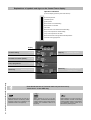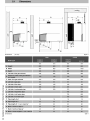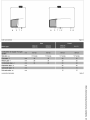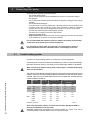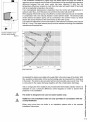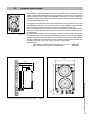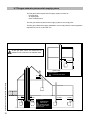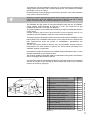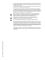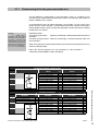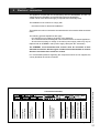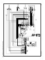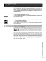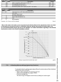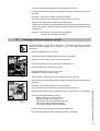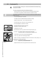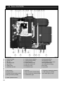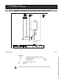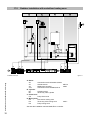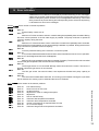
1
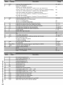
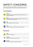
Explanations of symbols and signs on the Control Tower display.
Operation indication
(in the first display position by technical read out)
0
1
2
3
4
5
6
7
8
9
A
No heat requirement
Ventilation phase
Ignition phase
Burner active on central heating
Burner active on hot water
Fan check
Burner off when room thermostat is demanding
Pump overrun phase for central heating
Pump overrun phase for hot water
Burner off because of to high flow water temperature
Automatic venting programme
display
Central heating
on / off
Domestic hot water (DHW)
on / off
Pump programme
on / off
Installation Instructions Strebel Q-boiler range
Mode key
2
Step key
Reset key
Selecting chapters
Selecting chapters
Unlocking the boiler
in case of error
From Good-read out to Technical read out (and vice versa):
- Press 5 sec. on the STEP key.
Water pressure is to low (<0,7 bar), FILL
indication remains continuously visible,
the boiler is taken out of operation. The
installation needs to be topped up.
Water pressure is to low (<1,0 bar),
flashing FILL will alternate with indication
of water pressure, boiler power of 50% is
possible. The installation needs to be
topped up.
Water pressure is to high (>2,8 bar), if
HIGH indication remains continuously
visible, the boiler is taken out of operation.
The installation pressure needs to be
decreased by draining water.
1
2
3
4
5
6
7
8
9
10
11
12
13
14
15
16
17
18
19
Declaration of conformity ............................................................................................................. 3
Introduction .................................................................................................................................. 4
Regulations .................................................................................................................................. 4
Scope of the supply ...................................................................................................................... 6
Description of the boiler ............................................................................................................... 6
Mounting the boiler ....................................................................................................................... 6
5.1
Dimensions ....................................................................................................................... 7
Connecting the boiler ................................................................................................................... 9
6.1
Central heating system ..................................................................................................... 9
6.2
Expansion vessel ............................................................................................................ 11
6.2.1 Expansion vessel module ............................................................................................... 12
6.3
Underfloor heating system (plastic pipes) ....................................................................... 13
6.4
Gas connection ............................................................................................................... 13
6.5
Hot water supply ............................................................................................................. 13
6.6
Condensation drain pipe ................................................................................................. 14
6.7
Flue gas exhaust system and air supply system ............................................................. 15
6.7.1 Dimensions of the flue gas and air intake duct ................................................................ 18
External hot water cylinders ....................................................................................................... 19
Electrical connection .................................................................................................................. 20
Boiler controls ............................................................................................................................ 22
9.1
Explanation of the function keys ..................................................................................... 23
Filling and venting the boiler and installation .............................................................................. 24
10.1 Hot water supply ............................................................................................................. 24
Commissioning the boiler ........................................................................................................... 25
11.1 Central heating system ................................................................................................... 25
11.2 Hot water supply ............................................................................................................. 25
11.3 Adjustments .................................................................................................................... 26
11.4 Activating factory settings (green key function) ............................................................... 28
Isolating the boiler ..................................................................................................................... 29
Commissioning ........................................................................................................................... 29
13.1 Checking for contamination ............................................................................................. 29
13.2 Checking of the zero pressure control ............................................................................ 30
13.3 Checking the CO2 ............................................................................................................ 31
Maintenance ............................................................................................................................... 32
14.1 Frequency of maintenance .............................................................................................. 32
14.2 Maintenance activities ..................................................................................................... 33
14.3 Warranty ......................................................................................................................... 33
Technical specifications ............................................................................................................. 34
Parts of the boiler ....................................................................................................................... 35
Installation examples .................................................................................................................. 36
17.1 Radiator installation without thermostatic radiator valves ................................................ 36
17.2 Radiator installation with underfloor heating zone ........................................................... 37
Error indication ........................................................................................................................... 38
Declaration of conformity ........................................................................................................... 39
The appliance should only be installed by a Competent Gas Installer.
Work on the boiler must be carried out by a competent person, (Ref: Gas
Safety Installation and Use ) using correctly calibrated instruments with
current test certification.
Installation Instructions Strebel Q-boiler range
Content
3
1
Introduction
These instructions describe the functioning, installation, use and primary maintenance
of STREBEL central heating units for the United Kingdom and Ireland. Where necessary
the different regulations for each country are separately described.
These instructions are intended for the use by Corgi registered installers or registered
Bord Gais installers in connection with the installation and putting into operation of
STREBEL units. It is advisable to read these instructions thoroughly, well in advance of
installation. Separate instructions for use are supplied with the unit for users of STREBEL
central heating units. STREBEL is not liable for the consequences of mistakes or
shortcomings which have found their way into the installation instructions or user’s
manual. Further, STREBEL reserves the right to alter its products without prior
notification.
When delivering the unit, give the customer clear instructions concerning its
use; present the customer with the user’s manual and card.
Each unit is fitted with an identification plate. Consult the details on this plate to verify
whether the unit is compliant with its intended location, e.g.: gas type, power source
and exhaust classification.
Relevant Installation, Service and User manuals:
- BrainQ
Digital room thermostat
- MadQ
Cascade-/Zone controller
2
Regulations
The following regulations apply to installation of STREBEL central heating units:
Legislation and Regulations.
Gas Safety (Installation and Use). All gas appliances must by law, be installed by a
competent person, eg. Members of CORGI and in accordance with the current Gas Safety
Regulation. Failure to install appliance correctly could lead to prosecution.
Installation Instructions Strebel Q-boiler range
In addition to the above regulations this appliance must be installed in compliance with the
current IEE Regulations, the Building Standards (Scotland Consolidation) Regulations.
Regulations and bye laws of the Local Water Authority and the Current Health and Safety
Regulation.
4
The current, Electricity at Work Regulation must be complied with and also be in
accordance with the relevant and current editions of the British Standards.
The STREBEL S-HQ boiler is a certified appliance and must not be modified or installed
in any way contrary to this Installation Manual.
Manufacturers instructions must not be taken in any way as overriding statutory
obligations.
The STREBEL S-HQ is a central heating unit with an optional integrated hot water
function. These units must be connected according to these instructions and all
installation norms in respect of the part of the unit to be connected.
Observe the following rules of safety:
- All work on the unit must take place in a dry environment.
- STREBEL units may never be in operation without their housing, except in
connection with maintenance or adjustments (see Chapter 13 and 14).
- Never allow electrical or electronic components to come into contact with water.
Carry out the following tasks in connection with maintenance, etc. to an alreadyinstalled unit:
- Shut down all programmes
- Close the gas tap
- Remove the plug from the wall socket
- Close the stop cock of the unit’s intake connection
Take note of the following when maintenance or adjustments are needed:
- The unit must be able to function during these activities; for this reason, the unit’s
supply voltage, gas pressure and water pressure must be maintained. Ensure that
these is not a source of potential danger during these activities.
Following maintenance or other activities; always check the installation of all
parts through which gas flows (using leak-search spray).
Following maintenance or other activities, always replace the housing and
secure it with the screw behind the door at the front of the casing.
The following (safety) symbols may be encountered in these installation instructions
and on the unit:
This symbol indicates that the unit must be stored away from frost.
This symbol indicates that the packaging and/or contents can be damaged as
a result of insufficient care taken during transport.
KEY-symbol. This symbol indicates that assembly or dismantling, must be
carried out.
ATTENTION symbol. This symbol indicates that extra attention must be paid
in connection with a particular operation.
Useful tip or advice
Installation Instructions Strebel Q-boiler range
This symbol indicates that, whilst still in its packaging, the unit must be
protected from weather conditions during transport and storage.
5
3
Scope of the supply
The boiler is supplied ready for use. The supply kit is composed as follows:
•
•
•
•
•
•
4
Condensing
Retrieves heat from the
flue gasses. Water
condensates on the
heat exchanger.
Modulating
Higher or lower burning
according to the heat
demand.
Stainless Steel
Super solid kind of
steel which keeps its
quality for life. It will not
rust or erode in contrast to composition
materials, like aluminium.
Installation Instructions Strebel Q-boiler range
•
•
•
•
•
Template on the package wrapper;
Installation instructions
Operating manual;
Warranty card;
Benchmark logbook.
Description of the boiler
Room sealed boiler
The boiler retreives its
combustion air from
outside then discharges
the flue gasses to the
outside.
6
Boiler with casing;
Automatic vent (inside the boiler);
Safety valve (inside the boiler);
Suspension bracket
Draining valve with T-piece;
Fixing material consisting of plugs and
screws;
The STREBEL S-HQ boiler is a room sealed, condensing and modulating central heating
boiler, with or without an integrated hot water facility.
The boiler is provided with a compact stainless steel heat exchanger with smooth
tubes. A well thought out principal using durable materials.
The boiler burns gas for supplying warmth. The heat is transferred in the heat
exchanger to the water in the central heating system. By cooling down the flue gasses
condensate is formed. This results in high efficiency. The condensate, which has no
effect on the heat exchanger and the function of the boiler, is drained through an
internal siphon.
The boiler is provided with an intelligent control system (CMS Control Management
System). The boiler anticipates the heat demand of the central heating system or the
hot water facility.
When an outside sensor is connected to the boiler works weather dependantly. This
means that the boiler control measures the outside temperature and flow temperature.
With this data the boiler calculates the optimal flow temperature for the installation.
Explanation of the type indication:
Q = Type
51 = Nominal load in kW
C = Combi (S = Solo)
STREBEL Q 51C
Mounting the boiler
The room where the boiler will be placed must always be frost free.
It is NOT necessary to have a purpose provided air vent in the room or internal space in
which the boiler is installed. Neither is it necessary to ventilate a cupboard or
compartment in which the boiler is installed, due to the extremely low surface
temperature of the boiler casing during operation. Therefore the requirements of BS 6798,
Clause 12, and BS5440:2 may be disregarded.
The boiler can be mounted practically to any wall with the suspension bracket and the
enclosed fixing equipment. The wall must be flat and of sufficient strength in order to be able
to carry the boiler weight with its water content.
Above the boiler there must be at least 250 mm working space in order to be able to fit
a coaxial flue system or a twin supply. On the left side of the boiler at least 50 mm and
on the right side 10 mm must be reserved to allow fitting or removing of casing. The
location of the boiler can be determined by using the template located inside the boiler
packaging.
Lift the boiler only by the boilers rear wall
Installation Instructions Strebel Q-boiler range
5
7
6
Connecting the boiler
The boiler has the following connection pipes;
- The central heating pipes.
These can be connected to the installation by means of compression fittings;
- The gas pipe.
It is provided with a female thread into which the tail piece of the gas valve can be
screwed;
- The condensation drain pipe.
It consists of an oval 24 mm plastic pipe. The drain pipe can be connected to this
by means of an open connection. If the open connection is fitted in a different
location, then the pipe can be lengthened by means of a 32 mm PVC sleeve;
- The flue gas exhaust system and air supply system.
It consists of a concentric connection 80/125 mm.
- Cold and hot water pipes.
Only Combi boilers: These consist of 15 mm copper pipe and can be connected
to the installation by means of compression fittings.
It is recommended that isolation valves are fitted to all heating and hot water
connections to facilitate ease of future maintenace.
It is advisable to spray-clean all of the unit’s connecting pipes and/or to
spray-clean/blow-clean the installation before connecting it to the unit.
6.1
Central heating system
Connect the central heating system according to the actual regulations.
The boiler pipes can be connected to the installation by means of compression fittings.
Reducers should be used for connecting to thick-walled pipe (welded or threaded).
When removing the plastic sealing caps from the pipes, contaminated testing
water can be released.
The boiler has a self-adjusting and self-protecting control system for the load and the pump
capacity. By this means the temperature difference between the flow and return water is
checked. Table 3 shows the water displacement which supplies the circulation pump at
certain installation resistance.
Installation Instructions Strebel Q-boiler range
Boiler type
10
pump type
water flow rate
permissible installation
resistance
UPER
l/min
l/h
kPa
mbar
Q25C
20-60
16,2
972
29
290
Combi Q38C
20-70
24,6
1478
20
200
Q51C
20-70
30,1
1803
Q25S
20-60
9,7
583
47
470
Q25S
20-60
16,2
972
32
320
Q38S
20-70
24,6
1478
22
220
Q51S
20-70
30,1
1803
Q60S
20-70
38,9
2333
Solo
Installation resistance
table 3
A low velocity header must be connected to the Q51C, Q51S and Q60S to
prevent flow problems over the boiler.
STREBEL supplies the AA1OV09U Low velocity header for 1 boiler. This can be
connected directly under the boiler on the flow and return pipe.
6.2
Expansion vessel
The central heating system must be provided with an expansion vessel. The expansion
vessel which is used should be geared to the water content of the installation. The precharge pressure depends on the installation height above the mounted expansion vessel.
See table 4.
installation height above
the expansion vessel
pre-charge pressure
of the expansion vessel
5m
0,5 bar
10 m
1,0 bar
15 m
1,5 bar
choice of expansion vessel
table 4
All Combi boilers are provided with an expansion vessel connection. This pipe is
connected with the three way valve and boiler pump. This prevent the expanding water,
during hot water production, is being closed off from the expansion vessel, when the
thermostatic radiator valves are fully closed. A second expansion vessel in the installation
is not a problem.
In connection with correct functioning of the boiler it is necessary for the
expansion vessel to be connected to the expansion vessel pipe of the boiler.
Installation Instructions Strebel Q-boiler range
The Solo boilers are not provided with an expansion vessel connection. When one of
these Solo boilers is combined with a cylinder then one has to take into account that the
expansion vessel should be connected between the three-way valve and the boiler
circulation pump.
12
6.2
Expansion vessel module
The STREBEL Q25S and Q38S boilers can be provided with an expansion vessel
module. By this means the external expansion vessel is not required. This expansion
vessel module is placed behind the STREBEL S-HQ boiler, by which means the
expansion vessel is not noticeable. The content of the two expansion vessels is 20 litres.
The pre-charge pressure is 1 bar.
expansion vessel module
figure 4
The expansion vessel module can be supplied with the necessary pipes to connect with
the STREBEL S-HQ boiler. The connecting pipes for the installation correspond with
those of the boiler and have the same centre-to-centre distance to the wall.
When checking the expansion vessels these are accessible via the left, right and upper
sides. From these sides the tanks are also removable and the boiler does not have to
be dismantled.
The space which is required for mounting the expansion vessel module corresponds
with the required space for mounting an STREBEL S-HQ boiler. They included template
and mounting strip for the boiler which can be used for the expansion vessel module.
The boiler is fitted on to this after the expansion vessel module has been mounted. The
necessary mounting strip for the boiler is present on the module.
Article numbers:
- the expansion vessel module without pipe connections
AEM0209U
- pipe connections for expansion vessel module
ALE0004U
480
side view of the module with boiler (dimensions in mm)
figure 5
front view of the module with boiler (dimensions in mm)
figure 6
Installation Instructions Strebel Q-boiler range
105
wall
660
155
540
385
13
6.3
Underfloor heating system (plastic pipes)
When connecting or using an underfloor heating system, designed with plastic pipes, or
plastic pipes are used elsewhere in the installation,one should ensure that the plastic
pipes used comply with the DIN 4726/4729 standard. It is set out in this standard that
the pipes may not have oxygen permeability higher than 0.1 g/m³.d at 40°C. If the
system does not comply with this DIN standard, the underfloor heating component will
have to be separated from the central heating appliance by means of a plate
exchanger.
No recourse can be made to the terms of the warranty in the event of failure
to observe the regulations pertaining to plastic underfloor heating pipes.
6.4
Gas connection
The appliance pipe is fitted with an internal thread, into which the tail piece of the gas
tap can be screwed.
The gas supply must comply to the current Gas Safety Regulations.
The connection to the appliance must include a suitable method of disconnection and a
gas control cock must be installed adjacent to the appliance for isolation purposes. The
nominal inlet working gas pressure measured at the appliance should be 20 mbar for Nat
gas (G20).
Make sure that the gas pipe work does not contain dirt, particularly with new
pipes.
When the boiler has to be converted from natural gas to LPG, STREBEL provides
special kits for this purpose. Special instructions are supplied with the kit.
Always check the installation of all of the parts through which gas flows
(using leak-search spray)
6.5
Hot water supply
Installation Instructions Strebel Q-boiler range
Connection of the drinking water installation should be done according to the national
water laws.
14
The sanitary water pipes can be connected to the installation by means of compression
fittings. The cold water inlet on the Combi boilers must be provided with the following
(counted in the water flow direction):
Dosing valve (supplied), Safety group (consisting of an isolation valve, non-return valve
and expansion valve), Expansion vessel 6bar (potable water, blue).
A dosing valve must be fitted in the cold water pipe. The dosing valve ensures that a
quantity of water is supplied which has a guaranteed outlet temperature of 60°C
(assuming a cold water temperature of 10°C). The quantity of water is virtually
unaffected by the water pressure.
With a water pressure lower than 1.5 bar it is advisable to remove the inside mechanism
of the dosing valve.
Condensation drain pipe
STREBEL boilers produce condensate. This condensate must be drained otherwise the
boiler will not function.
The collecting condensation drain pipe should be connected to the drain by means of an
open connection. By this means the possibility of drain gases ending up in the boiler is
prevented. The drain connection should have a minimum diameter of 32mm.
Connect the condensation drain pipe according to the actual regulations.
The following components are connected to the collective condensation drain pipe:
- Condensation discharge;
- Safety valve;
Draining of the condensation water to the external rain guttering is not
permitted in view of the danger of freezing.
Before putting the boiler into operation fill the siphon with 300 ml of water.
Installation Instructions Strebel Q-boiler range
6.6
15
6.7 Flue gas exhaust system and air supply system
The flue gas exhaust system and air supply system consists of:
- Flue gas pipe;
- Air supply pipe;
- Roof or wall terminal.
The flue gas exhaust system and air supply system must comply with:
The flue gas outlet and air supply installation must comply with the current regulation
requirements. IG UP 10 and BS 715.
All flue gas parts, which are outside the fire
resistant cover, need to be in stainless steel.
PP
SS
Air filter
Open boiler
BoilerClass B
Free exhaust area
Installation Instructions Strebel Q-boiler range
SS
PP
16
PP
PP
SS
PP
PP/MW
PP/MW
PP/MW
Boiler Class C
Permitted only
when the air
intake and the flue gas
outlet are in the same
pressure area.
Room sealed system
Open boiler en roomsealed system
figure 8
The appliance connection diameter is 80/125 mm, to which the flue gas outlet and air
supply system can be fitted, with or without elbow pieces. The maximum permissible
pipe length is set out in Table 5.
It is also possible to use a parallel pipe connection of 2x 80mm. In this case a seperate
cover 125mm should be ordered.
We advise to build a simple flue gas system and air supply system out of table 6. For
further information about the available components of the flue gas and air supply
system we recommend you consult the Monopass Flue systems.
The STREBEL flue gas system is meant and designed solely the use on STREBEL
central heating boilers adjusted for Nat gas or LPG. The maximum flue gas
temperatures are below 70°C (full load 80/60°C)
The proper operation can be influenced harmfully by changes of or adjustments to the
correct set up.
Possible warranty claims will not be honoured if incorrect changes result in non
compliance with the installation manual or local rules and regulations.
The flue gas systems described in this document are solely suited for STREBEL central
heating boilers of the STREBEL boiler range. For this purpose the CE Certificate has
been supplemented under the Gastec nr: 0063BQ3021, 0063AS3538 and
0063AU3110.
The flue gas system should be built up using only STREBEL program products.
Combinations with other brands or systems are without written permission from
STREBEL Heating not permitted.
Horizontal flue system should always be installed sloping towards the boiler, in order
to avoid condensate lying in the flue system.
The minimum gradient is 50mm/Mtr. With the condensate running back to the boiler the
risk of ice forming at the terminal is reduced.
The terminal should be located where dispersal of combustion products is not impeded
and with due regard for the damage or discolouration that might occur to building
products in the vicinity (see fig 9).
A
figure 9
directly below an open window or other opening
mm
(e.g. air brick)
300
B below gutters, soil pipes or drain pipes
mm
75
C below eaves
mm
200
D below balconies or car port roof
mm
200
E from vertical drain pipes and soil pipes
mm
75
F from internal or external corners
mm
300
G above ground or below balcony level
mm
300
H from a surface facing a terminal
mm
600
I
from a terminal facing a terminal
mm
1200
J
from an opening in the car port (e.g. door
window) into dwelling
mm
1200
K vertically from a terminal on the same wall
mm
1500
L horizontally from a terminal on the same wall
mm
300
M horizontally from a vertical terminal to a wall
mm
300
Dimensions
table 6
Installation Instructions Strebel Q-boiler range
minimum
distance
terminal position for fan assisted boiler
17
In certain weather conditions condensation may also accumulate on the outside of the
air inlet pipe. Such conditions must be considered and where necessary insulation of the
inlet pipe may be required.
In cold and/or humid weather water vapour may condense on leaving the flue terminal.
The effect of such ‘plumeing’ must be considered.
The terminal must not be located in a place where it is likely to cause a nuisance.
For protection of combustibles, refer to IS 813 section 9.10.1. where the terminal is less
than 2m (6.6ft) above a pavement or platform to which people have access (including)
any balcony or flat roof the terminal must be protected by a guard of durable material.
A suitable guard is available from the country distributor.
Where a terminal is fitted below a window which is hinged at the top, and
where the hinge axis is horizontal, and the window opens outwards, the
terminal shall be 1m below the bottom of the window opening.
If the boiler is to be located under stairs, a smoke alarm meeting the
requirements of I.S. 409 or equivalent must be fitted.
The flue must be terminated in a place not likely to cause a nuisance.
For horizontal sections, the outlet system should always be fitted on an incline (50 mm/
m) sloping down towards the appliance so that no condensation water is able to
accumulate in the outlet system. The chances of icicles forming on the roof outlet is
minimised by causing the condensation water to run back towards the appliance. In the
case of horizontal outlets the inlet system should be fitted on an incline sloping down
towards the outside to prevent rainwater from coming in.
Installation Instructions Strebel Q-boiler range
The appliance produces a white wisp of condensation (plumeing). This wisp of
condensation is harmless, but can be unattractive, particularly in the case of outlets in
outside walls.
18
6.7.1
Dimensioning of the flue gas and air intake duct
The flue diameter is determined by the total length of the run, including for the
connection pipe, elbows fittings and terminal covers etc and the type and number of
boilers installed into the system.
An undersized flue pipe can lead to disorders. Look at table 1 for the choice of the
system and the correct diameter. The table below shows the maximum flue lengths
with the different boiler outputs. A longer flue gas length can be achieved by increasing
the diameter to ø 100mm.
Example:
A
25kW with a
concentric flue gas system
ø80/125mm has according to
the table a maximum flue
straight length of 31m In the
system that is going to be put in
there are 2 x 45° bends, so the
maximum flue gas length is
40 – ( 2 x 1.1 ) = 37.8 meters.
Explanation table 1:
Two pipe flue gas system: maximum noted length = distance between boiler and roof
terminal A
Concentric flue gas system: maximum noted length = distance between boiler and
roof terminal B
When using bends the noted value behind every bend should be deducted from the
maximum straight length.
Pipes with 60/100 diameter are only permitted on wall terminals in
combination with STREBEL boilers untill 25kW.
ø80mm
Maximum straight lenth 80
87° bend resistance length
45° bend resistance length
Maximum straight lenth 80
87° bend resistance length
45° bend resistance length
Maximum straight lenth 80
87° bend resistance length
45° bend resistance length
16-25 kW
26-38 kW
39-60 kW
A
in m
31
-1,5
-0,8
18
-1,5
-0,8
6
-1,5
-0,8
ø100mm
Maximum straight lenth 100
87° bend resistance length
45° bend resistance length
Maximum straight lenth 100
87° bend resistance length
45° bend resistance length
Maximum straight lenth 100
87° bend resistance length
45° bend resistance length
A
in m
40
-1,8
-0,9
39
-1,8
-0,9
18
-1,8
-0,9
B
in m
31
-2,8
-1,1
13
-2,8
-1,1
6
-2,8
-1,1
ø100/150mm
Maximum straight lenth 100/150
87° bend resistance length
45° bend resistance length
Maximum straight lenth 100/150
87° bend resistance length
45° bend resistance length
Maximum straight lenth 100/150
87° bend resistance length
45° bend resistance length
B
in m
40
-2,6
-1,1
34
-2,6
-1,1
10
-2,6
-1,1
Concentric flue system
ø60/100mm
16-25 kW Maximum straight lenth 60/100
87° bend resistance length
45° bend resistance length
26-38 kW
39-60 kW
B
in m
ø80/125mm
12 Maximum straight lenth 80/125
-1 87° bend resistance length
-1 45° bend resistance length
Maximum straight lenth 80/125
87° bend resistance length
45° bend resistance length
Maximum straight lenth 80/125
87° bend resistance length
45° bend resistance length
Dimensions flue gas system and air supply system
Table 5
Installation Instructions Strebel Q-boiler range
Two pipe flue system + chimney lining
19
7
External hot water cylinders
Depending of the comfort preferences different external hot water cylinders can be
connected to the boiler. The choice of the cylinder depends on the coil output. The coil
output must comply with the boiler output.
Installation Instructions Strebel Q-boiler range
A cylinder which is used in combination with aQ 51S of Q 60S, should have a minimal
capacity of 40 kW respectively 45kW (minimal ø28mm coil). The maximal permitted
pressure drop is respectively 20 and 10 kPa at a flow of respectively 1417 and 1587 l/h.
See installation example 16.2 on page 37 for the hydraulic connection.
20
8
Electrical connection
The appliance complies with the CE Machinery Directive 89/392/EEC. The EC Low
Voltage Directive 72/23/EEC and the EC EMC Directive 89/336/EEC.
A 230V -50Hz mains electrical supply is required fused externally at 5A.
The installation must continue to comply with:
-
the national rules for electrical installations.
The appliance must be connected to an earthed socket. this must be visible and within
reach.
The following general stipulations also apply:
- No changes may be made to the wiring of the appliance;
- All connections should be designed in accordance with the enclosed regulations.;
- Should it be necessary to change it, the mains power supply cable may only be
replaced with an STREBEL mains power supply cable (item No. S4407300).
The STREBEL room thermostat and controls must be connected to their
allocated connections. All other types or makes of room thermostats or controls
which are used must have a Volt free contact.
Connection terminalQ
24 Volts
maximum 100 mA
External safety contact
On/off thermostat or
control (Volt free)
outside sensor
external three-way
valve motor and
cylinder sensor
230 Volts
230 Volts for
external control
230 Volts for
external pump
mains power
supply
Connection terminal
room thermostat
tabel 6
boilercombinaties
figure 10
Installation Instructions Strebel Q-boiler range
For more detailed questions regarding the components which are not supplied, the
country distributor should be contacted.
21
22
electrical diagram
Installation Instructions Strebel Q-boiler range
figure 11
9
Boiler controls
The boiler is provided with a fully automatic microprocessor control, called CMS
Control Management System. This control simplifies operation by undertaking all
major control functions. Initially when power to the unit is switched on it will remain on
standby. There is no indication Led on, untill one of the programme keys is pressed. The
control panel display will show the relevant state. When the installation is empty the
display will show FILL.
The various parameters can be called up in two ways:
The Good-state or standard read out
The first way shows a simple display read out.
The boiler in operation will always show 'Good'. When a message is necessary this will
be shown instead of Good.
Technical read out
The second way is a technical read out. In normal situations the following will be shown:
• on the left the status in which the boiler is active;
• on the right the flow temperature;
• the water pressure in the installation.
When a message (error or blocking code) is necessary this will be shown instead of
the technical read out..
To switch over from the Good-state to the Technical read out (and vice versa):
- Press 5 sec. on the STEP-key.
When the system has been filled the automatic venting program starts, when a programme
has been selected, by pressing the key for Central Heating, DHW or pump programme
(
,
of
). The programme takes 17 minutes and stops automatically. After this
the unit will function normally. (See also 'Filling and venting the boiler and installation).
Installation Instructions Strebel Q-boiler range
On a call for heating or hot water the control system will select the required water control
temperature. This water temperature is called the T-set value. On a call for central
heating the boiler ignites first at low input. The input is then changed slowly to match the
load required. The boiler operates in this way to avoid excessive water noises and
temperature overshoot. On a call for hot water supply the T-set value of central heating
return water temperature is monitored. Depending on the amount of sanitary water which
is withdrawn from the DHW cylinder, the central heating return water temperature, from
which the input is adjusted, will vary.
23
9.1
Explanation of the function keys
When the pump is
switched on continuously
it can lead to undesired
heating up of the central
heating system during the
summer.I
-
Central Heating programme key.
Switching the Central Heating on or off (Led on/off);
-
Hot Water programme key.
Switching the Domestig Hot Water (DHW) facility on or off (Led on/off);
-
PC programme key.
adjusts the pump to continuous water circulation in the central heating system (Led
on), or according to the pump overrun times on the relevant programs (Led off);
•
Mode-key.
After briefly pressing, a selection of the data chapters can be retrieved.
After pressing for 5 seconds it is possible to enter the code as described in chapter
11.3;
Step-key.
After briefly pressing, the water pressure can be retrieved and pages per chapter
can be retrieved.
After pressing for 5 seconds it switches from the Good-state to technical read out
and vice versa;
Reset-key.
After briefly pressing, for:
- unlocking errors;
- ending the access code;
After pressing for 5 seconds an operating stop is made, for example, for activating
the automatic venting programme.
•
•
Installation Instructions Strebel Q-boiler range
Some keys have other functions.These functions are only active when according to the
procedure described in chapter 11.3, adjustment has to be changed or data must be
retreived from the CMS.
The other functions are:
24
-
Central Heating programme key :
-
Hot Water programme key:
PC programme key :
-
Step-key:
+ function;
- function;
store-function, which means that by means
of this key a modified setting is confirmed;
scrolling in a data chapter.
10 Filling and venting the boiler and installation
The central heating installation needs to be filled with potable water. For filling or
topping up the installation you use the filling loop according to the following procedure:
1 Switch on the power supply;
2 The diplay will show FILL;
3 All functions off (heating, DHW and pump);
4 Push briefly the 'STEP'-button: P x.x = water pressure in bar;
5 Open the filling loop (Indication on display increases);
6 Fill up slowly to 1.5 to 1.7 bar;
7 STOP appears on the display;
8 Close the filling loop;
9 De-aerate the complete installation, start at the lowest point;
10 Check the water pressure and if necessary top it up;
11 Close the filling loop;
12 Activate the functions in use (heating
, DHW
and/or pump
);
13 If A xx appears on the display, wait for 17 minutes;
14 Check the waterpressure and if necessary top it up to 1,5 to 1,7 bar
15 Close the filling loop;
16 Press the ‘STEP’-button;
17 Be sure that the filling loop is closed.
18 After the automatic de-aeration programm (A xx) is finished the boiler will return to
the Good state or Technical read out.
Check the water pressure regularly and top up the installation when necessary.
The working pressure of the installation should be between 1.5 and 1.7 bar when the
It can take a while before all air has disappeared from a filled installation.
Especially in the first week noises may be heard which indicate the presence
of air. The automatic air vent in the boiler will make this air disappear, which
means the water pressure can reduce during this period and therefore topping up with water will have to be done.
10.1
Hot water supply
Apply the water pipe pressure to the cylinder (open main valve and/or stop valve of the
safety group).
Vent the cylinder and the hot water installation by opening a hot water tap. Leave the
tap open for as long as required until all air has disappeared from the cylinder and the
pipes and only water is flowing from the tap.
Installation Instructions Strebel Q-boiler range
installation is cold.
25
11 Commissioning the boiler
Before the boiler is fired, ensure that the boiler and the system are well vented and free
of air. Purge the gas line between the gas meter and the boiler and carry out a gas
soundness test as specified in the current Gas Safety Regulations.
The boiler does not require adjustment of the burner pressure and air quantity because
it is self adjusting and is factory set at the correct value.
11.1
Central Heating system
Provided there is a heat requirement from the thermostat or control, the central heating
programme will be put into operation by means of the
key (central heating
programme). The circulation pump will start circulating and the boiler will start the
burner.
11.2
Hot water supply
Provided there is a heat requirement from the cylinder the hot water programme will
Installation Instructions Strebel Q-boiler range
be put into operation by means of the
26
key (hot water programme).
11.3
Adjustments
When the boiler is installed it is in principal ready for use. All adjustments of the boiler
control are already pre-programmed for a heating system with radiators/convectors
with a flow temperature of 85°C. The adjustments are described in the Parameter
chapter on page 28.
In certain cases adjustment have to be alterd in case of :
-
Lower flow temperature
More boilers in Cascade, i.e..
Read through the Parameter chapter to adjust the boiler to its installation.
Contact STREBEL Ltd. in case of doubt.
Please follow next procudere to alter adjustments:
Altering adjustments
STEP 1
Press the Mode-key for 5 secondss.
The display shows COdE followed by an arbitrary number;
STEP 2
Press by means of the + or the - key until the code C123 is shown;
STEP 3
Press the STORE-key to confirm the code (code blinks1 x).
Now you have acces to the installer level. There are 4 chapters:
•
PARA
Parameters
•
INFO
Information chapter (no adjustments possible)
•
SERV
Service chapter
•
ERRO
Error-chapter (no adjustments possible)
STEP 4
Press briefly the MODE-key to select one of the 4 chapters, i.e. PARA;
STEP 5
Press once or more briefly on the STEP-key to select a Parameter
(parameter visible on the left, value on the right) ;
STEP 6
Alter the value, if necessary/possible, by means of the + or the - key
STEP 7
Press briefly on the STORE-key to confirm the alteration.
When you have to change more values, repeat from step 5.
STEP 8
Press once or more on the MODE-key until StBY or Good is shown:
After a few seconds the text StBY will be replaced by the technical read-out
or Good-state (Depending from the position the acces code is keyed in)
When you want to return from an arbitrary position to the original read out
press once or more on the MODE-key until StBY is shown.
When during 20 minutes no single key is used the display will return automatically to
its original read-out (Good state or technical read out)
Installation Instructions Strebel Q-boiler range
The content of the chapters is described on the following pages.
27
12
Isolating the boiler
In some situations it may be that the entire boiler must be switched off. By switching
off the three keys with the lamps for central heating, hot water and pump programme
,
or
), the boiler is switched off. Leave the plug in the wall socket, which
(
means the circulation pump and the three-way valve are activated once every 24 hours
in order to prevent jamming.
In the event of frost danger it is advisable to drain the boiler and/or the
installation.
13 Commissioning
Work on the boiler must be carried out by a competent person, (Ref: Gas
Safety Installation and Use ) using correctly calibrated instruments with current
test certification.
To commission the boiler the casing has to be removed. The casing is locked with a
screw behind the door on the front and the top of the casing is hooked behind a locking
edge. After removing this screw the casing must be lifted at the bottom by which means
it is released from the locking edge. Then the casing can be removed forward.
The boiler settings, such as burner pressure and adjustment of the air quantity are
unnecessary, due to the fact that the boiler operates with a so-called zero pressure
control. This means the correct gas quantity is controlled by the suction operation of
the fan. The fine adjustment which is carried out at the factory is once-only, which
means that adjusting of these values is unnecessary. Only in case of replacing of the
gas valve, venturi and/or fan the zero pressure and the CO2 adjustment has to be
checked and, if necessary, adjusted at the right value.
Always check the installation of all parts through which gas flows (using
leak-search spray)
Installation Instructions Strebel Q-boiler range
13.1
30
Checking for contamination
In order to be able to check the boiler for contamination in the following running years
it is advisable to measure the maximum air displacement in the boiler when putting the
boiler into operation. This value can be different with each type of boiler.
In order to be able to measure this value follow the next procedure:
Check point contamination
figure 12
-
Press the MODE-key for 5 seconds.
-
The diplay will show COdE followed by an arbitrary number;
-
Select by means of the + or the - key the code C123;
-
Press the Store-key to confirm the code (code blinks 1 x);
-
Press the MODE-key until SERV is shown;
-
Press the STEP-key until 2 is shown;
alternately 2 and OFF will be shown.
13.2
-
Turn the upper measuring nipple on the gas valve open (fig. 12);
-
Connect the hose of the digital pressure gauge to the upper measuring nipple of the
gas valve
-
Press the + key until the maximum value is achieved;
The fan will function to its maximum revolutions (burner stays off)
-
Measure the under pressure and write down this value.
At the next commissioning visit this value may drop 20% of its original value on the
moment of intallation. When this value is dropped more than 20% the boiler needs
maintanance.
-
Press the - key until OFF is shown (keep key pressed)
With this the procedure is finished.
Checking of the zero pressure control
Check point contamination
figure 13
-
Press the MODE-key for 5 seconds.
-
The diplay will show COdE followed by an arbitrary number;
-
Select by means of the + or the - key the code C123;
-
Press the Store-key to confirm the code (code blinks 1 x);
-
Press the MODE-key until SERV is shown;
-
Press the STEP-key once until 1 is shown;
alternately 1 and OFF will be shown.
-
Turn the upper measuring nipple on the gas valve open (fig. 13);
-
Connect the hose of the digital pressure gauge to the upper measuring nipple of the
gas valve
-
Press the - key until the minimum value is achieved;
The fan will function to its minimum revolutions (burner is active)
-
Measure the negative pressure. Value should be +/- 0 to -4Pa (+/- 0 to -0,04 mbar).
-
If the zero pressure deviates too much:
Remove black cover of the gas valve
Remove cap with Torx key (fig. 14)
Turn slightly the Torx screw behind the cap:
Turn left is positive pressure deviation
Turn right is negative pressure deviation
-
Ending this procedure is done by pressing the Reset key.
-
Proceed by checking the CO2 value and correct it if necessary.
Adjustment zero pressure
figure 14
Installation Instructions Strebel Q-boiler range
The zero pressure control is set at the factory. To measure this value you need a
difference pressure gauge with a range of +0,2 to -0,8 mbar. Follow the next
procedure:
31
13.3
Checking the CO2
The CO2 percentage is factory-set. This has to be checked at commissioning,
maintance and faults.
This can be checked by means of the following procedure:
- Remove the black cover of the gas valve by unscrewing the sealed screw.
-
Put the boiler into operation and take care that it can deliver its heat;
Tip: If there is no demand for heat on CH, turn the hot water tap completely open and
measure the CO2.
checkpoint CO2
figure 15
-
Press the MODE-key for 5 seconds.
-
The diplay will show COdE followed by an arbitrary number;
-
Select by means of the + or the - key the code C123;
-
Press the Store-key to confirm the code (code blinks 1 x);
-
Press the MODE-key until SERV is shown;
-
Press the STEP-key once until 1 is shown;
alternately 1 and OFF will be shown.
-
Calibrate the CO2 meter ;
-
Place the lance of the CO2 meter into the check point (see fig. 15);
-
Press the + key until the maximum value (in kW) is achieved;
The boiler will burn on full load (value on display in kW)
-
Check Table 7 for the correct CO2 percentage (page 35)
-
Let the CO2 meter do its measuring procedure.
-
Adjust, if necessary, the adjustment screw to correct the CO2 value (see fig. 16).
Installation Instructions Strebel Q-boiler range
Ending the CO2 measuring procedure:
- Press the - key until OFF is shown (keep key pressed).
With this the procedure has ended..
32
adjustment screw CO2
figure 16
-
Replace the black cover on the gas valve and fix it with the screw.
14 Maintenance
Maintenance or changes to the unit may only be carried out by an authorised technician.
14.1
The frequency of maintenance
We advise to carry out an inspection/overhaul to the boiler every year, but at least after
two years and an overhaul every four years, depending from the running hours
mentiond in the warranty conditions. When doing this the circumstances of the boiler’s
location must be taken into account. From this one can determine whether to deviate
from this advice. Please contact the country distributor for further guidance on the
frequency ans service requirements.
Maintenance activities
To carry out the maintenance activities please follow the next procedure:
- switch off the power supply;
- remove the screw behind the door on the front of the casing;
- Lift the casing and remove it towards the front.
The air box
- remove the transparant air box;
- clean the box with a cloth with a simple (non-abrasive) cleaning agent;
The fan unit and burner cassette
- remove the electrical connection plug from the gas valve and fan motor;
- loosen the nut of the gas pipe under the gas valve;
- replace the gasket by a new one;
- loosen the front cross head screw of the black plastic silencer;
- after this turn the two clamping rods ¼ turn and remove them by pulling them
forward. Note the right turning direction (red indicator);
- slightly lift the fan unit and remove it towards the front of the heat exchanger;
- remove the burner cassette out of the fan unit;
- check the burner cassette on wear, pollution and possible cracks. Clean the burner
cassette with a soft bruch and vacuum cleaner. If burners are cracked replace the
complete burner cassette;
- replace the gaskets between burner and fan unit and the gasket between fan unit
and heat exchanger;
- check the venturi and the gas-air distribution plate for pollution and clean this part,
if necessary with a soft brush and vacuum cleaner. If the air box contains a lot of
dirt it is plausible that the fan itself is dirty as well. To clean this, the fan has to be
removed from the hood and the venturi. Clean the fan with a soft brush and a
vacuum cleaner. Replace the gasket and ensure that all gaskets of the fan parts are
mounted correctly.
Heat exchanger
- check the heat exchanger for contamination. Clean this if necessary with a soft
brush and a vacuum cleaner. Prevent dirt falling down into the heat exchanger.
Flushing the heat exchanger from the top down is not permitted
Refitting of the components is done in reverse order.
Make sure that during refitting the clamping rods they are put in the right
position. They should be turned vertical.
Installation Instructions Strebel Q-boiler range
14.2
33
Ignition electrode
The replacement of the electrode is only necessary when the electrode is worn off. This
can be checked by measuring the ionisation current. The minimum ionisation current has
to be higher the 4µA on full load.
If the viewing glass is damaged the complete electrode must be replaced.
Replacement goes as follows:
- remove the electrical connections of the electrode;
- press the clips on both sides of the electrode to both sides and remove the complete
electrode;
- remove and replace the gasket;
Refitting of the components is done in reverse order.
Siphon and condensate tray
- first remove the condensate cup;
Check this for pollution. If there is no sign of strong pollution it is not necessary to
clean the condense tray. If there is a strong pollution in the cup it is necessary to
remove and clean the condensate tray;
- remove the inner siphon pipe which remains in the condensat tray;
- check the O-rings of the cup as well as those from the pipe and replace if necessary;
- clean both part by flushing it with clean water;
- grease the O-rings again wit acid free O-ring grease to make fitting easier;
- if there is a leak at the siphon cup or tray the complete siphon unit has to be replaced
by S44516xx;
- remove the plug from the flue gas sensor if present;
- turn the two short clamping rods ¼ turn and remove them by pulling them forward;
Note the right turning direction (red indicator);
- lift the flue gas pipe out of the condensate tray;
- press the condensate tray carefully downwards and remove it by pulling it forward;
- replace the gasket between condensate tray and heat exchanger by a new one;
- clean the condensate tray with water and a hard brush;
- check the condensate tray on leaks.
Refitting is done in reverse order.
Note thate the gasket of the condensate tray seals completely.
Make sure that during refitting the clamping rods they are put in the right
position. They should be turned vertical.
Replace always all removed gaskets of dismanteled parts during the
maintenance activities.
Installation Instructions Strebel Q-boiler range
Put the boiler into operation and check the CO2 (see page 32).
34
14.3
Warranty
For warranty conditions we refer to the warranty card supplied with the boiler.
STREBELSHQ
16 Parts of the boiler
4
2
1
3
5
8 19
18
7
6
20 16
9
T1
P1
T5
T2
T3
G
A
21
R
C
10
E
W
K
11
13 14
15
17
Installation Instructions Strebel Q-boiler range
Strebel Q-boiler
36
1
2
3
4
5
6
7
heat exchanger
ignition unit
fan unit
air inlet damper
gas valve
safety valve
automatic air vent
T1 flow sensor
T2 return sensor
T3 cylinder sensor DHW (combi)
T5 flue gas sensor (if fitted)
P1 water pressure sensor
figure 15
8
9
10
11
12
13
14
ceramic burner cassette
cylinder DHW (Combi)
operating panel
Control Tower (CMS)
water filter return CH
three-way valve
circulation pump
15
16
17
18
19
20
21
safety group DHW
expansion vessel
thermostatic mixing valve
flue gas discharge
combustion air supply
air boiler
type plate
G
A
R
C
gas pipe
flow connection central heating
return connection central heating
condensation pipe
E expansion vessel pipe (Q51C)
K cold water pipe (combi)
W hot water pipe (combi)
17 Installation examples
17.1
Radiator installation without thermostatic radiator valves
BP
figure 16
A Boiler:
A0
A1
A4
tra
BP`
Connection terminal Strebel Q-boiler
BrainQ thermostat
RSC
Outside sensor
ARV12
Thermostatic radiator valve
By-pass
Use alway a by pass in combination with thermostatic radiator valves.
Installation Instructions Strebel Q-boiler range
installation example
37
17.2
Radiator installation with underfloor heating zone
Installation Instructions Strebel Q-boiler range
installation example
38
figure 17
A Boiler:
A0
Connection terminal Strebel Q-boiler
A4
Outside sensor
ARV12
A9
MadQ zone controller
23BC
A10
Connection terminal MadQ built in
B Cylinder:
B3
Cylinder sensor
B5
Three-way valve cylinder
C Direct zone:
C6
Pump direct zone
D Mixing zone:
D2
Flow sensor mixing zone
D5
Three way valve mixing zone
230V~
D6
Pump mixing zone
See also the installation manual MadQ Zone controller.
18 Error indication
A detected error is indicated on the display by means of blocking or error messages.
A distinction should be made between these two messages due to the fact that blocking
can be of a temporary nature, however, error messages are fixed lockings. The control
will try its utmost to prevent locking and will temporarily switch off the unit by blocking
it. Hereunder is a list of some messages.
Blocks
with a number in the last 2 positions.
Block 01:
External safety contact cut off
Block 11:
Maximum 'T of flow and return sensor in central heating has repeatedly been exceeded. During
the block normal operation of the hot water supply is possible. The pump continues to operate at
minimum capacity during the block.
Block 12:
Maximum 'T of flow and return sensor in domestic hot water has repeatedly been exceeded.
During the block normal operation of the central heating installation is possible. During the block the
pump continues to operate at minimum capacity.
Block 60:
Incorrect parameter setting of the minimum or maximum power.
Block 67:
A 'T has been detected between flow and return sensor whereas the burner is not in operation.
After the 'T has disappeared the block will disappear.
Block 80:
Maximum flue gas temperature has been exceeded (if present). The block will not be cancelled
until the flue gas temperature has arrived below the temperature.
Block 81:
The flue gas sensor is not connected although it was connected to the control. The burner is
blocked until the flue gas sensor is reconnected.
Block 82:
The flue gas sensor has short-circuited, heat requirement blocked and pump capacity at
minimum.
Block 85:
The control has not detected a water flow. The venting cycle is started. If during this cycle water
flow is detected, the venting cycle is ended and the burner is released.
with a number in the last two positions.
Error 00:
Error 01:
Error 02:
Error 04:
Error 05:
Error 12:
Error 18:
Error 19:
Error 28:
Error 69:
Error 80:
Poor flame-forming
short-circuit of 24 volt circuit
no flame-forming
adjustment or error for voltage interruption
adjustment
fuse 24 volt/3AT faulty
maximum flow temperature exceeded
maximum return temperature exceeded
number of revolutions not reported back from fan
no or incorrect display
maximum flue gas sensor temperature exceeded
Installation Instructions Strebel Q-boiler range
Error
39
This renewed publication cancels all previous installation instructions. The company reserves the right to change the specifications and dimensions without prior notice.
STREBEL LTD. • 1F, Albany park industrial estate • Frimley road, Camberley • Surrey GU15 2PL
Telephone: (01276) 685422 • Fax: (01276) 685405 • E-mail: [email protected] • Internet: www.strebel.co.uk
E. & O. E.