1
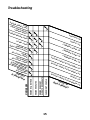
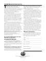
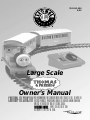
78-1011-250
9/02
Large Scale
Owner’s Manual
CAUTION-ELECTRIC TOY
NOT RECOMMENDED FOR CHILDREN UNDER EIGHT YEARS OF AGE. AS WITH ALL
ELECTRIC PRODUCTS, PRECAUTIONS SHOULD BE OBSERVED DURING HANDLING
AND USE TO REDUCE THE RISK OF ELECTRIC SHOCK.
TRANSFORMER RATINGS - INPUT: 120 VAC 60 HZ 28W
DC OUTPUT: 6-16V; 19.2 VA TOTAL.
Introduction
ongratulations on your purchase of the
Large Scale Thomas & Friends Train
Set! Before you assemble your train set for
operation, this instruction book should be
read by everyone who will be operating it.
You will learn important information on
train set operation and the proper use of
your set in order to avoid damage. If you
have any remaining questions about your
train set or accessories, contact your authorized Lionel Service Center using the listing
included in a separate flyer in your train set
box. After you have read this booklet, assembled your train, and plugged in the trans-
former, you will be ready to enjoy many
hours of railroading fun.
As with all LIONEL LARGE SCALE engines,
this set was designed o run on Lionel Large
Scale Track and has an operating voltage
range of 6-16 volts D.C. only. CAUTION:
USING A.C. POWER WILL DAMAGE
THE MOTOR IN YOUR LOCOMOTIVE.
Parents should periodically inspect the
power pack for potential hazards and have it
repaired if necessary. See the Lionel Service
Station listing for the address of the nearest
authorized Service Station.
C
Table of contents
Track Layout
Joining the track sections
Creating a Large Scale layout
Attaching the Lock-On to the track
Connecting the Lock-On to the track
3
4
5
6
Controller operations
Understanding short circuits
Connecting the power supply
Operating the power supply
7
8
9
Train operations
Arranging the train on the track
Operating the knuckle couplers
Installing and operating hook and loop couplers
Attaching the 3 Thomas Faces
Picking Up Thomas
Locomotive Care
Troubleshooting
Limited Warranty/Lionel Service
10
10
11
12
13
14
15
16
Visit the Thomas & Friends website at:
www.thomasthetankengine.com
Q Gullane (Thomas) Limited 2002
The following Lionel marks may be used throughout this instruction manual and are protected under
law. All rights reserved.
Lionel®, TrainMaster®, Odyssey®, RailSounds™, CrewTalk™, TowerCom™, DynaChuff™,
StationSounds™, Pullmor®, ElectroCoupler™, Magne-Traction®, CAB-1 Remote Controller®,
PowerMaster®, Lionel ZW®, ZW®, PowerHouse®, TMCC™, Lionelville™
2
Track layout
Joining the track sections
oin the track sections together by inserting the pins of each track section into
the rail openings of another section. Refer
to Figure 1. Track joints must be tight for
good electrical contact, and the track should
fit together firmly.
If the rail openings have become enlarged
so that the track fits loosely together, pinch
the rail around a track pin with a pair of pli-
ers. If any pins fall out of the track and are
missing, replace them immediately. The rails
should be kept clean, dry, and free from oil
and grease. Clean off tarnish and dirt spots
with any commercial metal polishing pad to
keep your track in top condition. Wipe the
track with a clean soft cloth dampened with
track cleaner from the Lionel Maintenance
Kit (available separately, 6-62927).
J
Figure 1. Track assembly
3
Track layout
Creating a Large-Scale layout
he layout shown in Figure 2 can be
assembled using the twelve track sections supplied with this set.
Extra sections of track are available from
your authorized Lionel dealer. Add on to your
circle to build your own railroad empire!
T
NOTE: 12 curved track sections = circle layout
Track Diameter 51”
Figure 2. Circle of track
4
Track layout
Attaching the Lock-On to the track
o attach the Lock-On onto the track, first
place the Lock-On under any curved section of the track between the rail ties. Fit the
flange of the outside rail into the squared
brass contact on the Lock-On. Next, press
the Lock-On upward so the spring contact
snaps onto the inner rail. See Figure 3. The
Lock-On should now be attached to the track
as shown in Figure 5 on page 6.
T
SQUARED BRASS CONTACT
SPRING CONTACT
BRASS FLANGE OF
THE OUTSIDE RAIL
Figure 3. Lock-On attachment
5
Track layout
Connecting the controller wires to the Lock-On
he wire coming out of the controller
splits into two thinner wires that are
stripped on the ends. These stripped wires
will be inserted into the Lock-On. This is
done by pressing down the upper half of the
clip until the metal loop in the lower part
projects through the top. Insert the bare wire
end into the loop and release the clip, as
illustrated in Figure 4 below. Spring tension
will hold the wire tight. The wire positions
are interchangeable.
T
Figure 4. Wire connections
on the actual controller is much longer
than appears in the illustration.
R
The set-up should now look something like
the one in Figure 5. You will find the wire
Figure 5. Completed track connections
6
Controller operations
Understanding short circuits
engine), or by two bare wires touching each
other at the track Lock-On. Some other
causes of short circuits might be staples,
nails, paper clips, or other metallic objects
lying across the rails.
An overload condition could be caused by
carrying too much weight inside the cars, or
by holding the engine while it is under
power, or by a sudden start or direction
change.
After operating the power pack for a while
you will find it warm to the touch. It is the
nature of all electrical power equipment to
become warm when in use. If your power
pack is loaded to capacity, it is a good idea
to let it cool down after an hour or two of
continuous use. Be sure to unplug the power
pack when not in use.
he power pack furnished with this train
set has been listed by the Underwriters
Laboratories, Inc. and has been carefully
tested to assure proper performance. This
controller is equipped with a built-in circuit
breaker that will alternately cut off and
restore the flow of power to the track whenever a short circuit exists until the cause of
the short circuit is eliminated. This circuit
breaker is incorporated into the controller to
protect the power pack from possible permanent damage. It will not protect the locomotive or electrically operated accessories.
T
NOTE: The transformer must be unplugged
from the wall socket when a short circuit
is noticed, and the short circuit must be
corrected.
A short circuit is caused by a direct connection across the rails (such as a derailed
Parents should periodically inspect the power pack for potential hazards such as a broken
or damaged case and have it repaired or replaced. See the Lionel Service Station listing for
information and the address of the nearest Authorized Service Station.
7
Controller operations
Connecting the power supply
W
ith the throttle in the OFF position,
plug in the wall power pack to a stan-
dard wall outlet, then plug the power pack
into the controller jack. See Figure 6.
POWER
PACK
CONTROLLER
JACK
FORWARD / REVERSE SWITCH
R
L
FUL ED
SPE
F
OF
NOTE: The speed control
dial should always be in
the OFF position when the
power pack is first
plugged in.
Figure 6. Power supply connection
8
Controller operations
Operating the train
fter you have assembled the track layout, place the locomotive and cars on
the track (see page 10 and 11). Before coupling the cars, make sure the wheels are
properly set on the rails. Once your train is
ready, have an adult plug the wall pack into
any wall outlet. Next, advance the transformer dial until the train begins to move.
To change directions, turn the speed control to off to stop the train, then change the
position of the direction switch. Increase the
throttle, and the engine is now traveling in
the reverse direction. Refer to Figure 7.
It should be noted that, while power is
continually increased as the controller knob
is turned to the right, it will not drive the
train until the knob is in the approximate
position shown in the illustration above. As
the load on the engine increases, (by adding
cars for the engine to pull for example) the
amount that the knob needs to be turned to
the right to run the train will increase.
A
R
L
FUL ED
E
P
S
OF
Directional control switch
Figure 7. Direction control switch
9
F
Train operations
Arranging the train on the track
fter the track is assembled, place
Thomas, Annie, and Clarabel on the
track, making sure that all wheels are properly set on the rails. The engine and two
coaches should be positioned as follows:
Thomas the Tank Engine - Annie - Clarabel.
You may want to arrange the coaches as they
appear in the books and on TV. Annie travels
facing Thomas, and Clarabel travels facing
away from Thomas. Refer to Figure 8.
A
THOMAS THE TANK ENGINE
CLARABEL
ANNIE
Figure 8. Arranging the set on the track
Operating the knuckle couplers
To join the cars together, open at least one
coupler by pressing up on the plunger located on the bottom of the coupler, then push
the cars together on any part of your track
with the couplers lined up.
ANNIE
Plunger, push up to open
Figure 9. Knuckle couplers
10
Train operations
Installing and operating hook and loop couplers
face. Place a coupler with hook and loop on
the other end of the coach.
he hook and loop style couplers included
with this set may be used in place of the
knuckle couplers that are installed on the
engine and coaches. To replace the couplers
follow the instructions below.
T
Engine installation
Loosen the two rear screws on the bottom of
the engine. Carefully lift the rear cover plate
off the gear box and slide the coupler off its
pivot post.
Slide a coupler with hook and loop over the
pivot post. Be sure the centering tab pin fits in
the support post inside the gear box. Use the
first coupler mounting hole (nearest the end
of the coupler). Tighten the two cover screws.
Annie and Clarabel
Turn the coach over and remove the screw
securing each coupler. Remove the knuckle
coupler and place the hook or loop coupler
in its place, aligning the screw post with the
third hole in the coupler mounting tab (the
hole that is furthest away from the end of
the coupler). Replace the screw to secure the
coupler.
On Clarabel, place one coupler with an
attached hook on the end of the coach with
the painted face. Place a coupler with loop
only on the other end of the coach.
On Annie, place a coupler with loop only
on the end of the coach with the painted
To couple the Annie and Clarabel coaches
together, simply push the hook into the
center of the loop, being careful to locate
the hook between the ribs. To uncouple the
coaches, push the tab on the hooked coupler
of the Annie coach. Refer to Figure 10.
CLARABEL
ANNIE
UNCOUPLER
BUTTON
RIBS
HOOK SIDE OF COUPLER
Lionel Part No. 818-5120-401 (with hooks)
LOOP SIDE OF COUPLER
818-5120-405 (without hooks)
Make sure that the hook is attached between the two ribs on the loop side
of the coupler!
Figure 10. Hook and loop coupler.
11
Train operations
Attaching the 3 Thomas Faces
T
hree interchangeable facial expressions
(surprised, tired and angry) easily slip
SURPRISED
on and off Thomas for fun and imaginative
play. Refer to Figure 11.
TIRED
ANGRY
Figure 11. Interchangeable faces
that the smiling Thomas face cannot be
removed. Refer to Figure 12.
To attach one of the faces, carefully position
it in front of the permanent smiling Thomas
face and push it straight on. To remove it,
simply pull it straight off. Please remember
Figure 12. Attaching the faces
12
Train operations
Picking Up Thomas
N
ever pick up the Thomas Engine by the
cab since the removable cab top may
come loose and the engine may drop. This is
illustrated in Figure 13.
WRONG WAY TO PICK UP THOMAS
Figure 13. Picking up Thomas incorrectly
Be sure to pick up the engine around the
middle as illustrated in Figure 14. This pro-
vides better stability.
RIGHT WAY TO PICK UP THOMAS
Figure 14. Picking up Thomas correctly
13
Train operations
Locomotive Care
o not attempt to disassemble and/or
lubricate your locomotive. All locomotives have been pretested and the necessary
moving parts have been sufficiently lubricated for life at the factory and should run
correctly. If you have difficulty with the
operation of your locomotive, please return
it to an authorized Lionel Trains Service
Center or the Factory Service Department for
proper service. See the Service section on
page 16 for additional information.
It is very important to keep the track and
wheels free from dirt and grease. Wipe them
with a soft cloth whenever they get dirty. This
will help the engine run more efficiently.
D
14
CO
RR
AC ECT
TIO IVE
N
&S
HO
SH
&S
EM
BL
R
TC
IR
OR
HO
R
CU
TC
IR
TC
IR
ITS
ITS
Y
LY
BL
PR
O
CA BABL
U
E
SE
PO
W
UN ER
P
LUG PACK
GE
INC
D
BE ORR
CO TWEEECT W
N
T
RO N TR IRING
LLE AC
SH
R K&
O
CO RT C
N
TRO IRCU
LLE IT ON
R
SH
OR
TC
T
R
A
CK IRCU
IT O
N
TRA
C
NO K CO
T
SEC NNEC
TIO
UR
E
NS
ITS
CU
CU
CARS WON'T COUPLE
P
PA
CK
&
AC
K
AS
S
KA
MB
EM
ENGINE RUNS VERY
SLOWLY OR OVERHEATS
ER
AC
K
ON
ER
ER
P
AC
SS
E
AS
S
ENGINE HESITATES
O
CK
OW
R
R
CK
ENGINE WILL NOT RUN
PO
W
eL
e
PO
W
eP
eT
AC
K
eT
R
eT
AC
K
eL
O
UP
PROBLEM
S
ee
Se
Se
Se
Se
Se
Se
Se
Se
eC
O
15
D
Y
IRT
Y
ON
LIN
TRA
CK
D
I
R
TY
EN
GIN
E
WH
LO
EEL
OS
S
LO E WI
OS
R
E C ING
/
ON
E
CA
CTI
R
ON
S
W TUR
A
N
Y
ED
WR
ON
G
G
Troubleshooting
Limited Warranty/Lionel Service
his Lionel product, including all
mechanical and electrical components,
moving parts, motors and structural
components, except for light bulbs, is warranted to
the original consumer-purchaser, for one year
against original defects in materials or
workmanship when purchased through an
authorized Lionel merchant.
This warranty does NOT cover normal wear
and tear, light bulbs, defects appearing in the
course of commercial use, or damage resulting
from abuse or misuse of the product by the
purchaser. Transfer of this product by the original
consumer-purchaser to another person voids this
warranty. Modification of this product voids this
warranty.
Any warranted product which is defective in
original materials or workmanship and is delivered
by the original consumer-purchaser to Lionel
L.L.C. or an authorized Lionel L.L.C. Service
Center, together with proof of original purchase
will, at the option of Lionel L.L.C., be repaired or
replaced, without charge for parts or labor. In the
event the defective product cannot be repaired, and
a replacement is not available, a refund of the
original purchase price will be granted. Any
products on which warranty service is sought must
be sent freight or postage prepaid, as
transportation and shipping charges are not
covered by the warranty.
T
In no event shall Lionel L.L.C. be
liable for incidental or
consequential damages.
Some states do not allow the exclusion or
limitation of incidental or consequential damages,
so the above exclusion may not apply to you.
This limited warranty gives you specific legal
rights, and you may have other rights which vary
from state to state.
Instructions for Obtaining Service
If service for this Lionel L.L.C. product is
required, bring the item, along with your dated
sales receipt and completed warranty information
to the nearest Authorized Lionel Service Center.
Your nearest Lionel Service Center can be found by
calling 1-800-4-Lionel, or by accessing our
Website at www.lionel.com.
If you prefer to send your product back to
Lionel L.L.C. for repair in Michigan, you must first
call 586-949-4100 or FAX 586-949-5429, or write
to Customer Service, P.O. Box 748, New Baltimore,
MI 48047-0748, stating what the item is, when it
was purchased and what seems to be the problem.
You will be sent a return authorization letter and
label to ensure your merchandise will be properly
handled upon receipt.
Once you have received your return
authorization and label, make sure that the item
is packed to prevent damage during shipping and
handling. We suggest that you use the product’s
original packaging. This shipment must be
prepaid and we recommend that it be insured.
Please make sure you have followed all of the
above instructions carefully before returning any
merchandise for service. You may choose to have
your product repaired by one of our Authorized
Lionel Service Centers after its warranty has
expired. A reasonable service fee will be charged.
Warranty Information
Please complete the information below and
keep it, along with your dated sales receipt. You
must present this and your dated sales receipt
when requesting warranty service.
Name ____________________________
Address ____________________________
Place of Purchase ____________________
Date of Purchase
____________________
Product Number ______________________
Product Description____________________
________________________________
©2002 LIONEL LLC, CHESTERFIELD, MI 48051-1956
UNITED STATES OF AMERICA
PRINTED IN U.S.A.