1
PRIMERGY TX200 S3 Configuration Sheets
About this manual
A
Configuration Sheets of Hardware
Use this form to record the hardware configuration and various settings of your server.
B
Configuration Sheets of BIOS Setup Utility Parameters
Use this form to record the settings of the BIOS Setup Utility.
C
Configuration Sheets of Remote Management Controller's Web Interface
Use this form to record the settings of the Remote Management Controller Web interface.
D
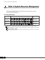
Table of System Resource Management
The I/O port address that can be selected with various expansion cards is the following tables.
E
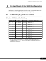
Design Sheet of the RAID Configuration
Use this form to record the definitions of the disk groups (or the physical packs) and the logical drives in the RAID
configuration (array configuration).
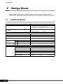
F
Design Sheet
Use this form to record the software settings.
G
Accident Sheet
Use this form to record any failures that occur in your server.
1
Product Names
The following expressions and abbreviations are used to describe the product names used in this manual.
Product names
PRIMERGY TX200 S3
®
Microsoft Windows
Server™
Expressions and abbreviations
This server or the server
2003 R2, Standard Edition
Windows Server 2003 R2,
Standard Edition
Microsoft® Windows Server™ 2003 R2, Enterprise Edition
Windows Server 2003 R2,
Enterprise Edition
Microsoft® Windows Server™ 2003, Enterprise Edition
Windows Server 2003,
Enterprise Edition
Microsoft® Windows Server™ 2003, Standard Edition
Windows Server 2003, Standard
Edition
Microsoft® Windows Server™ 2003 R2, Standard x64 Edition
Windows Server 2003 R2,
Standard x64 Edition
Microsoft® Windows Server™ 2003 R2, Enterprise x64 Edition
Windows Server 2003 R2,
Enterprise x64 Edition
Microsoft® Windows Server™ 2003, Standard x64 Edition
Windows Server 2003, Standard
x64 Edition
Microsoft® Windows Server™ 2003, Enterprise x64 Edition
Windows Server 2003 R2,
Enterprise x64 Edition
Microsoft® Windows® 2000 Server
Windows 2000 Server
®
®
Microsoft Windows 2000 Advanced Server
Windows 2000 Advanced Server
Microsoft®
SP
Windows
Server™
2003 Service Pack
Windows
2003
Windows
2000
Microsoft® Windows® 2000 Service Pack
Trademarks
Microsoft, Windows, MS, Windows Server are registered trademarks of the Microsoft Corporation in the USA and other
countries.
Intel, Celeron and Pentium are registered trademarks or trademarks of Intel Corporation or its subsidiaries in the USA
and other countries.
All other hardware and software names used are trademarks or registered trademarks of their respective manufacturers.
Other product names are copyrights of their respective manufacturers.
All Rights Reserved, Copyright© FUJITSU LIMITED 2006
2
PRIMERGY TX200 S3 Configuration Sheets
Contents
A Configuration Sheets of Hardware . . . . . . . . . . . . . . . . . . . . . . . 4
B Configuration Sheets of BIOS Setup Utility Parameters . . . . . . 6
B.1 Parameters in the Main Menu . . . . . . . . . . . . . . . . . . . . . . . . . . . . . . . . . . . .6
B.2 Parameters in the Advanced Menu . . . . . . . . . . . . . . . . . . . . . . . . . . . . . . . .8
B.3 Parameters in the Security Menu . . . . . . . . . . . . . . . . . . . . . . . . . . . . . . . . .14
B.4 Parameters in the Server Menu . . . . . . . . . . . . . . . . . . . . . . . . . . . . . . . . . .15
C Configuration Sheets of Remote Management Controller's Web
Interface. . . . . . . . . . . . . . . . . . . . . . . . . . . . . . . . . . . . . . . . . . . 17
C.1 Parameters in the iRMC Information . . . . . . . . . . . . . . . . . . . . . . . . . . . . . .17
C.2 Parameters in the Power On/Off . . . . . . . . . . . . . . . . . . . . . . . . . . . . . . . . .17
C.3 Parameters in the Fans . . . . . . . . . . . . . . . . . . . . . . . . . . . . . . . . . . . . . . . .18
C.4 Parameters in the Temperature . . . . . . . . . . . . . . . . . . . . . . . . . . . . . . . . . .18
C.5 Parameters in the Server Management Information . . . . . . . . . . . . . . . . . .19
C.6 Parameters in the Network Settings . . . . . . . . . . . . . . . . . . . . . . . . . . . . . . .20
C.7 Parameters in the SNMP Trap Alerting . . . . . . . . . . . . . . . . . . . . . . . . . . . .21
C.8 Parameters in the Email Alerting . . . . . . . . . . . . . . . . . . . . . . . . . . . . . . . . .21
C.9 Parameters in the User Management . . . . . . . . . . . . . . . . . . . . . . . . . . . . .22
C.10 Parameters in the BIOS Text Console . . . . . . . . . . . . . . . . . . . . . . . . . . . .25
D Table of System Resource Management . . . . . . . . . . . . . . . . . . 26
E Design Sheet of the RAID Configuration . . . . . . . . . . . . . . . . . . 27
E.1 For PG-140FL (MegaRAID SAS 8300XLP) . . . . . . . . . . . . . . . . . . . . . . . . .27
E.2 For PG-142E3 (MegaRAID SCSI 320-2) . . . . . . . . . . . . . . . . . . . . . . . . . . .29
E.3 For Integrated Mirroring SAS . . . . . . . . . . . . . . . . . . . . . . . . . . . . . . . . . . . .31
F Design Sheet . . . . . . . . . . . . . . . . . . . . . . . . . . . . . . . . . . . . . . . . 32
F.1 RAID/Disk Wizard . . . . . . . . . . . . . . . . . . . . . . . . . . . . . . . . . . . . . . . . . . . . .32
F.2 OS Wizard (Windows 2003 Install Wizard) . . . . . . . . . . . . . . . . . . . . . . . . . .33
F.3 OS Wizard (Windows 2000 Install Wizard) . . . . . . . . . . . . . . . . . . . . . . . . . .40
F.4 Application Wizard . . . . . . . . . . . . . . . . . . . . . . . . . . . . . . . . . . . . . . . . . . . . .46
G Accident Sheet . . . . . . . . . . . . . . . . . . . . . . . . . . . . . . . . . . . . . . 47
3
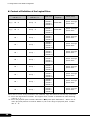
A Configuration Sheets of Hardware
A
Configuration Sheets of Hardware
Use this form to record the hardware configuration and various settings of your server.
Put a check mark in parentheses of your server settings.
3.5-inch Internal Options
Installation 3.5 inch internal option
Installed position
Bay 1
( ) 73.4 GB
( ) 146.8 GB
Bay 2
( ) 73.4 GB
( ) 146.8 GB
Bay 3
( ) 73.4 GB
( ) 146.8 GB
Bay 4
( ) 73.4 GB
( ) 146.8 GB
Bay 5
( ) 73.4 GB
( ) 146.8 GB
Bay 6
( ) 73.4 GB
( ) 146.8 GB
5-inch Internal Options
Installed position
Bay 1*
Bay 2 or Bay 3
Both bay 2 and
bay 3
Installation 5 inch internal option (Product ID)
( ) Internal DVD-RAM unit (PG-DVA102D)
-
( ) Internal DAT72 unit (PG-DT504)
-
( ) Internal VXA2 unit (PG-VX201)
5 or 6
( ) Internal LTO2 unit (PG-LT201)
5 or 6
( ) Internal LTO3 unit (PG-LT301)
5
( ) Internal hard disk unit bay conversion kit (PG-BC 103)
-
*) C D-ROM drive / floppy disk drive is standard installed in bay 1.
RAM Modules
Installation slot
Memory Bank 1
Memory Bank 2
Memory Bank 3
4
SC SI ID
Slot 1A
Slot 1B
Slot 2A
Slot 2B
Slot 3A
Slot 3B
Installation RAM module
( ) 512 MB
( ) 1 GB
( ) 2 GB
( ) 512 MB
( ) 1 GB
( ) 2 GB
( ) 512 MB
( ) 1 GB
( ) 2 GB
PRIMERGY TX200 S3 Configuration Sheets
CPU
Installation C PU
Installed position
( ) Xeon Processor 5050/2x2MB(FSB667MHz)
( ) Slot 1
( ) Slot 2
( ) Xeon Processor 5060/2x2MB(FSB1066MHz)
( ) Slot 1
( ) Slot 2
( ) Xeon Processor 5080/2x2MB(FSB1066MHz)
( ) Slot 1
( ) Slot 2
( ) Xeon Processor 5130/4MB(FSB1333MHz)
( ) Slot 1
( ) Slot 2
( ) Xeon Processor 5160/4MB(FSB1333MHz)
( ) Slot 1
( ) Slot 2
Same C PU must be installed in Slot 1 and Slot 2.
Option Cards
Expansion card (Product ID)
PC I slot location
1
2
3
4
5
SAS array controller card (PG-140FL)
( )
-
-
-
-
Fibre C hannel C ontroller (PG-FC 202)
-
-
( )
( )
-
LAN card (PG-2861)
-
-
( )
( )
-
LAN card (PG-1892)
( )
-
-
-
( )
LAN card (PG-1882)
( )
-
-
-
( )
LAN card (PG-1862)
( )
-
-
-
( )
SC SI array controller card (PG-142E3)
( )
( )
-
-
( )
SC SI card (PG-1281)
( )
( )
-
-
( )
-: Indicates that this item cannot be installed.
5
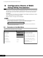
B Configuration Sheets of BIOS Setup Utility Parameters
B
Configuration Sheets of BIOS
Setup Utility Parameters
Use this form to record the settings of the BIOS Setup Utility. If you have not changed
the initial value, put a check mark in parentheses of "The initial values have been
unchanged".
The initial values in the frame can be changed. If you change any setting, put a check
mark in parentheses of the "Setting" column.
Keep the values on the gray zones unchanged.
` Follow the procedure below to start the BIOS Setup Utility.
When the following message appears on the screen during POST, press the [F2] key while the
message is displayed. When POST is completed, the Main menu screen appears.
<F2> BIOS Setup/ <F12> Boot Menu
If the system starts before starting the BIOS Setup Utility, press the [Ctrl] + [Alt] + [Delete] keys
simultaneously and restart the system.
B.1
Parameters in the Main Menu
( )The initial values have been unchanged.
I tem
I nitial value
Sys tem T ime:
H H :M M :SS
D is plays /Sets pres ent time.
Sys tem D ate:
M M /D D /Y Y Y Y
D is plays /Sets pres ent date.
D is kette A :
1 .4 M
( )N one ( )3 6 0 K ( )1 .2 M ( )7 2 0 K
C D -RO M
L inks to the Standard I D E s ubmenu
> Standard I D E
> Boot O ption
6
Setting
L inks to the Boot O ption s ubmenu
Bas e M emory:
6 4 0 KB
D is plays the available bas e memory
s ize below 1 M B.
E xtended M emory:
xxxM
D is plays the memory s ize.
PRIMERGY TX200 S3 Configuration Sheets
Standard IDE Submenu
( )The initial values have been unchanged.
I tem
Standard I D E :
I nitial value
Setting
[C D -RO M ]
P I O M ode:
PIO 4
D is plays the P I O mode s upported by
devic es .
D M A M ode:
U DMA 2
D is plays the D M A mode s upported by
devic es .
Firmware:
x.xx
D is plays the firmware vers ion.
Boot Options Submenu
( )The initial values have been unchanged.
I tem
Setting
I nitial value
Boot O ptions
P O ST E rrors
H alt O n A ll E rrors
( )N o H alt O n A ny E rrors
Keyboard C hec k
E nabled
( )D is abled
SM E rror H alt
D is abled
( )E nabled
Fas t Boot:
D is abled
( )E nabled
Q uiet Boot:
D is abled
( )E nabled
N um L oc k:
A uto
( )O n ( )O ff
Boot M enu:
E nabled
( )D is abled
M ultiBoot for H D s :
E nabled
( )D is abled
> Boot Sequenc e
L inks to the Boot Sequenc e s ubmenu.
Boot Sequence Submenu
( )The initial values have been unchanged.
I tem
I nitial value
Setting
Boot O ptions
> Boot Sequenc e
C D -RO M D rive
- D is kette
Standard
- H ard D rive
Bus 0 2 D ev 0 E )P C I RA I D A dapter
(Write down the boot s equenc e)
(
)C D - RO M D rive
(
)D is kette
(
)H ard D rive
(
)L egac y L A N C ard
A lternate D evic e
L egac y L A N C ard
7
B Configuration Sheets of BIOS Setup Utility Parameters
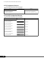
B.2
Parameters in the Advanced Menu
( )The initial values have been unchanged.
I tem
I nitial value
Setting
Setup Warning
Setting items on this menu to inc orrec t values
may c aus e your s ys tem to malfunc tion
8
> P eripheral C onfiguration
L inks to P eripheral C onfiguration s ubmenu
> P C I C onfiguration
L inks to P C I C onfiguration s ubmenu
> A dvanc ed Sys tem C onfiguration
L inks to A dvanc ed Sys tem C onfiguration
s ubmenu
> P ower O n/O ff
L inks to P ower O n/O ff s ubmenu
> IP MI
L inks to I P M I s ubmenu
Res et c onfiguration D ata:
No
( )Y es
M ultiproc es s or Spec ific ation:
1 .4
( )1 .1
PRIMERGY TX200 S3 Configuration Sheets
Peripheral Configuration Submenu
( )The initial values have been unchanged.
I tem
I nitial value
Setting
P eripheral C onfiguration
Serial 1 :
A uto
( )D is abled ( )E nabled ( )O S C ontrolled
Serial P ort1 A ddres s : * 1
3 F8 h,I RQ 4
( )2 F8 h,I RQ 3 ( )3 E 8 h,I RQ 4
( )2 E 8 h,I RQ 3
Serial M ultiplexer:
Sys tem
( )iRM C
Serial 2 :
A uto
( )D is abled ( )E nabled ( )O S C ontrolled
Serial 2 A ddres s : * 2
2 F8 h,I RQ 3
( )3 F8 h,I RQ 4 ( )3 E 8 h,I RQ 4
( )2 E 8 h,I RQ 3
P arallel:
A uto
( )D is abled ( )E nabled
P arallel M ode:
Bidirec tion
( )P rinter ( )E P P ( )E C P
P arallel A ddres s : * 3
3 7 8 h,I RQ 7
( )2 7 8 h,I RQ 5 ( )3 BC h,I RQ 7
U SB H os t C ontroller:
E nabled
( )D is abled
U SB 2 .0 H os t C ontroller:
E nabled
( )D is abled
U SB BI O S Supported D evic es :
A uto
( )N one ( )Keyboard/M ous e ( )A ll
U SB Boot D elay:
0s
( )3 s ( )6 s ( )9 s
U SB BI O S H ot-P lug:
E nabled
( )D is abled
> A T A C ontroller C onfig
L inks to A T A C ontroller C onfig s ubmenu
D is kette C ontroller:
E nabled
M ous e C ontroller:
A uto D etec t
( )D is abled
( )D is abled ( )E nabled
O nboard V ideo:
E nabled
( )D is abled
L A N C ontroller:
E nabled
( )D is abled
L A N Remote Boot:
D is abled
( )P XE
M anagement L A N :
E nabled
( )D is abled
* 1 : A ppears when "E nabled" is s elec ted for [Serial 1 ].
* 2 : A ppears when "E nabled" is s elec ted for [Serial 2 ].
* 3 : A ppears when "E nabled" is s elec ted for [P arallel].
ATA Controller Config Submenu
( )The initial values have been unchanged.
I tem
Setting
I nitial value
A T A C ontroller C onfig
S- A T A M ode:
N ative
P - A T A M ap to: * 1
Sec ondary
( )C ompatible ( )A H C I
( )D is abled ( )P rimary
P rimary I D E C hannel:
E nabled
( )D is abled
Sec ondary I D E C hannel: * 1
E nabled
( )D is abled
T ertiary I D E C hannel: * 2
E nabled
( )D is abled
Q uaternary I D E C hannel: * 2
E nabled
( )D is abled
* 1 : A ppears when " C ompatible" is s elec ted for [S- A T A M ode].
* 2 : A ppears when other than " C ompatible" is s elec ted for [S- A T A M ode].
9
B Configuration Sheets of BIOS Setup Utility Parameters
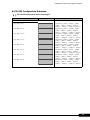
PCI Configuration Submenu
( )The initial values have been unchanged.
I tem
I nitial value
Setting
P C I C onfiguration
> P C I SL O T S C onfiguration
L inks to P C I SL O T S C onfiguration
> P C I I RQ C onfiguration
L inks to P C I I RQ C onfiguration s ubmenu
PCI SLOTS Configuration Submenu
( )The initial values have been unchanged.
I tem
Setting
I nitial value
P C I SL O T S C onfiguration
P C I Slot 1 C onfiguration
O ption RO M SC A N :
E nabled
( )D is abled
E nabled
( )D is abled
D is abled
( )E nabled
D is abled
( )E nabled
D is abled
( )E nabled
E nabled
( )D is abled
P C I Slot 2 C onfiguration
O ption RO M SC A N :
P C I Slot 3 C onfiguration
O ption RO M SC A N :
P C I Slot 4 C onfiguration
O ption RO M SC A N :
P C I Slot 5 C onfiguration
O ption RO M SC A N :
P C I Slot 1 0 C onfiguration
O ption RO M SC A N :
10
PRIMERGY TX200 S3 Configuration Sheets
PCI IRQ Configuration Submenu
( )The initial values have been unchanged.
I tem
I nitial value
Setting
P C I I RQ C onfiguration
P C I I RQ L ine 1 :
A uto
P C I I RQ L ine 2 :
A uto
P C I I RQ L ine 3 :
A uto
P C I I RQ L ine 4 :
A uto
P C I I RQ L ine 5 :
A uto
P C I I RQ L ine 6 :
A uto
P C I I RQ L ine 7 :
A uto
P C I I RQ L ine 8 :
A uto
( )D is abled ( )I RQ 3 ( )I RQ 4 ( )I RQ 5
( )I RQ 6 ( )I RQ 7 ( )I RQ 9 ( )I RQ 1 0
( )I RQ 1 1 ( )I RQ 1 2 ( )I RQ 1 4 ( )I RQ 1 5
( )D is abled ( )I RQ 3 ( )I RQ 4 ( )I RQ 5
( )I RQ 6 ( )I RQ 7 ( )I RQ 9 ( )I RQ 1 0
( )I RQ 1 1 ( )I RQ 1 2 ( )I RQ 1 4 ( )I RQ 1 5
( )D is abled ( )I RQ 3 ( )I RQ 4 ( )I RQ 5
( )I RQ 6 ( )I RQ 7 ( )I RQ 9 ( )I RQ 1 0
( )I RQ 1 1 ( )I RQ 1 2 ( )I RQ 1 4 ( )I RQ 1 5
( )D is abled ( )I RQ 3 ( )I RQ 4 ( )I RQ 5
( )I RQ 6 ( )I RQ 7 ( )I RQ 9 ( )I RQ 1 0
( )I RQ 1 1 ( )I RQ 1 2 ( )I RQ 1 4 ( )I RQ 1 5
( )D is abled ( )I RQ 3 ( )I RQ 4 ( )I RQ 5
( )I RQ 6 ( )I RQ 7 ( )I RQ 9 ( )I RQ 1 0
( )I RQ 1 1 ( )I RQ 1 2 ( )I RQ 1 4 ( )I RQ 1 5
( )D is abled ( )I RQ 3 ( )I RQ 4 ( )I RQ 5
( )I RQ 6 ( )I RQ 7 ( )I RQ 9 ( )I RQ 1 0
( )I RQ 1 1 ( )I RQ 1 2 ( )I RQ 1 4 ( )I RQ 1 5
( )D is abled ( )I RQ 3 ( )I RQ 4 ( )I RQ 5
( )I RQ 6 ( )I RQ 7 ( )I RQ 9 ( )I RQ 1 0
( )I RQ 1 1 ( )I RQ 1 2 ( )I RQ 1 4 ( )I RQ 1 5
( )D is abled ( )I RQ 3 ( )I RQ 4 ( )I RQ 5
( )I RQ 6 ( )I RQ 7 ( )I RQ 9 ( )I RQ 1 0
( )I RQ 1 1 ( )I RQ 1 2 ( )I RQ 1 4 ( )I RQ 1 5
11
B Configuration Sheets of BIOS Setup Utility Parameters
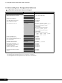
Advanced System Configuration Submenu
( )The initial values have been unchanged.
I tem
I nitial value
Setting
A dvanc ed Sys tem C onfiguration
BI O S Work Spac e L oc ation:
Expansion ROM Area
( )T op of Bas e M emory
M emory Redundanc y:
D is abled
( )M irroring
C P U M is matc h D etec tion:
E nabled
( )D is abled
C P U T imeout C ounter:
D is abled
( )E nabled
C P U Frequenc y (G H z):
A utomatic
・ For Xeon ® P roc es s or 5 1 6 0
( )2 .0 0 ( )2 .3 3 ( )2 .6 6 ( )3 .0 0
・ For Xeon ® P roc es s or 5 1 3 0
unavailable
・ For Xeon® P roc es s or 5 0 8 0
( )3 .1 9 ( )3 .4 6 ( )3 .7 2
・ For Xeon® P roc es s or 5 0 6 0
unavailable
・ For Xeon® P roc es s or 5 0 5 0
( )1 .9 9 ( )2 .1 6 ( )2 .3 2 ( )2 .4 9
( )2 .6 6 ( )2 .8 2 ( )2 .9 9
H yper-T hreading:* 1
D is abled
( )E nabled
L imit C P U I D func tions :
D is abled
( )E nabled
C P U T hermal M anagement:* 2
E nhanc ed
( )Standard
C P U H alt M ode:
E nhanc ed
( )Standard
N X M emory P rotec tion:
D is abled
( )E nabled
C P U M C Status C lear:
N ext Boot
( )E nabled ( )D is abled
E nhanc ed SpeedStep: * 3
D is abled
( )E nabled
V irtualization T ec hnology:
D is abled
( )E nabled
H ardware P refetc h:
E nabled
( )D is abled
A djac ent Sec tor P refetc h:
E nabled
( )D is abled
H igh P rec is ion E vent T imer:
D is abled
( )E nabled
I /O A T :
D is abled
( )E nabled
* 1 : N ot appears when Xeon® P roc es s or 5 1 3 0 /5 1 6 0 is ins talled.
* 2 : A ppears when Xeon® P roc es s or 5 1 3 0 /5 1 6 0 is ins talled.
* 3 : N ot appears when Xeon® P roc es s or 5 0 6 0 /5 1 3 0 is ins talled.
12
PRIMERGY TX200 S3 Configuration Sheets
Power On/Off Submenu
( )The initial values have been unchanged.
I tem
I nitial value
Setting
P ower O n/O ff
P ower O ff Sourc e
Software:
E nabled
( )D is abled
P ower Button:
E nabled
( )D is abled
P ower O n Sourc e:
BI O S C ontrolled
( )A C P I C ontrolled
Remote:
E nabled
( )D is abled
LA N:
E nabled
( )D is abled
Wake U p T imer:
D is abled
( )E nabled
Wake U p T ime: * 1
[0 0 :0 0 :0 0 ]
Wake U p M ode: * 1
D aily
( )M onthly
1
( )[1 ~3 1 ]
P revious State
( )A lways O ff ( )A lways O n
Wake U p D ay: * 2
P ower Failure Rec overy:
* 1 : A ppears when "E nabled" is s elec ted for [Wake U p T imer].
* 2 : A ppears when "M onthly" is s elec ted for [Wake U p M ode].
IPMI Submenu
( )The initial values have been unchanged.
I tem
Setting
I nitial value
IP MI
SE L L oad
xx%
C lear Sys tem E vent L og:
D is abled
D is plays perc entage of s tored SE L
( )E nabled
E vent L og Full M ode:
O verwrite
( )M aintain
iRM C T ime Sync :
E nabled
( )D is abled
> Sys tem E vent L og
D is plays Sys tem E vent L og
> SD RR Brows er
D is plays information of s ens ors
> L A N Settings
L inks to L A N Settings s ubmenu
LAN Settings Submenu
( )The initial values have been unchanged.
I tem
Setting
I nitial value
L A N Settings
DHC P :
D is abled
( )E nabled
L oc al I P addres s
[0 0 0 .0 0 0 .0 0 0 .0 0 1 ]
I P addres s of iRM C
[
.
.
.
]
Subnet mas k
[0 0 0 .0 0 0 .0 0 0 .0 0 0 ]
Subnet mas k
[
.
.
.
]
G ateway addres s
[0 0 0 .0 0 0 .0 0 0 .0 0 0 ]
G ateway addres s
[
.
.
.
]
13
B Configuration Sheets of BIOS Setup Utility Parameters
B.3
Parameters in the Security Menu
( )The initial values have been unchanged.
I tem
I nitial value
Setup P as s word
N ot ins talled
D is plays whether or not the s etup
pas s word is s et.
Sys tem P as s word
N ot ins talled
D is plays whether or not the s ys tem
pas s word is s et.
Set Setup P as s word:
P res s E nter
E nter the s etup pas s word.
Setup P as s word L oc k:
Standard
( )E xtended
Set Sys tem P as s word:
P res s E nter
E nter the s ys tem pas s word * 1
Sys tem P as s word M ode:
Sys tem
( )Keyboard * 2
Sys tem L oad:
Standard
( )D is kette/C D RO M L oc k
Setup P rompt:
E nabled
( )D is abled
V irus Warning:
D is abled
( )E nabled ( )C onfirm
D is kette Write:
E nabled
( )D is abled
Flas h Write:
E nabled
( )D is abled
* 1 : C an be s et when [Setup P as s word] is s et.
* 2 : C an be s et when [Sys tem P as s word] is s et.
14
Setting
PRIMERGY TX200 S3 Configuration Sheets
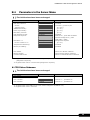
B.4
Parameters in the Server Menu
( )The initial values have been unchanged.
I tem
O /S Boot T imeout:
Setting
I nitial value
D is abled
( )E nabled
A c tion:
Res et
( )C ontinue ( )P ower C yc le
T imeout V alue:
0
(
)[0 ~1 0 0 ]
A SR&R Boot D elay:
2
(
P ower C yc le D elay:
7
(
)[1 ~3 0 ]
)[0 ~1 5 ]
(
)[0 ~7 ]
( )E nabled
Boot Retry C ounter:
3
H ide D iagnos tic I D E :
D is abled
D iagnos tic Sys tem:
D is abled
N ext Boot: * 1
Boot O ption
( )D iagnos tic s Sys tem
0
(
( )I D E D rive ( )D is k N ot I ns talled
( )Remote I mage D is k ( )L A N
( )RSB U SB ( )iRM C
D evic e I ns tanc e: * 2
T emperature M onitoring:
D is abled
)[0 ~1 5 ]
( )E nabled
M emory Sc rubbing:
D is abled
( )E nabled
> C P U Status
L inks to C P U Status s ubmenu
> M emory Status
L inks to M emory Status s ubmenu
> C ons ole Redirec tion
L inks to C ons ole Redirec tion s ubmenu
* 1 : A ppears when "I D E D rive" , "Remote I mage D is k" , "L A N " , "RSB U SB" or "iRM C " is s elec ted for
[D iagnos tic s Sys tem].
* 2 : A ppears when "L A N " is s elec ted for [D iagnos tic s Sys tem].
CPU Status Submenu
( )The initial values have been unchanged.
I tem
I nitial value
Setting
C P U Status
C P U 1 Status
E nabled
( )Failed * 1 ( )D is abled * 2
C P U 2 Status
E nabled
( )Failed * 1 ( )D is abled * 2
* 1 : A ppears when C P U I E RR oc c urs . T his c an be c hanged to " E nabled" only.
* 2 : A ppears when C P U is removed.
15
B Configuration Sheets of BIOS Setup Utility Parameters
Memory Status Submenu
( )The initial values have been unchanged.
I tem
I nitial value
Setting
M emory Status
M emory M odule 1 A
E nabled
( )Failed* 1 ( )D is abled * 2
M emory M odule 2 A
E nabled
( )Failed* 1 ( )D is abled * 2
M emory M odule 3 A
E nabled
( )Failed* 1 ( )D is abled * 2
M emory M odule 1 B
E nabled
( )Failed* 1 ( )D is abled * 2
M emory M odule 2 B
E nabled
( )Failed* 1 ( )D is abled * 2
M emory M odule 3 B
E nabled
( )Failed* 1 ( )D is abled * 2
* 1 : A ppears when memory error oc c urs . T his c an be c hanged to "E nabled" only.
* 2 : A ppears when memory module is removed.
Console Redirection Submenu
( )The initial values have been unchanged.
I tem
I nitial value
Setting
C ons ole Redirec tion
C ons ole Redirec tion
D is abled
( )E nabled
P ort * 1
Serial1
( )Serial2
Baud Rate * 1
9600
( )1 2 0 0 ( )2 4 0 0 ( )4 8 0 0 ( )1 9 .2 K
( )3 8 .4 K ( )5 7 .6 K ( )1 1 5 .2 K
P rotoc ol * 1
V T100+
( )V T 1 0 0 ( )V T 1 0 0 ,8 bit
( )P C -A N SI ,7 bit ( )P C -A N SI
Flow C ontrol * 1
C T S/RT S
( )N one ( )XO N /XO FF
M ode * 1
E nhanc ed
( )Standard
* 1 : A ppears when "E nabled" is s elec ted for [C ons ole Redirec tion].
16
PRIMERGY TX200 S3 Configuration Sheets
C
Configuration Sheets of Remote
Management Controller's Web Interface
Use this form to record the settings of the Remote Management Controller Web
interface. If you have not change the initial value, put a check mark in parentheses of
"The initial values have been unchanged".
The initial values in the frame can be changed.
C.1
Parameters in the iRMC Information
( )The initial values have been unchanged.
I tem
I nitial value
iRM C I nformation
D is plays iRM C information.
SSL and SSH C ertific ate
C ertific ate U pload
C ertific ation for SSL &SSH
N ot U pload
( )N ot U pload
N ot U pload
L ic ens e Key ( N ot dis played input data.)
( )N ot U pload ( )U pload
L ic ens e Key
U pload
C.2
Setting
( )U pload
Parameters in the Power On/Off
( )The initial values have been unchanged.
I tem
I nitial value
Res tart
Setting
G ives a direc t ins truc tion on power c ontrol
of the s erver.
P ower Res tore P ollic y
BI O S s etting is
reflec ted
( )A lways P ower off
( )A lways P ower on
( )Res tore to powered s tate prior to power
los s
P ower O n/O ff T ime
Sets s c hedule O n/O ff time.
N one
N one
N one
O n T ime[
O n T ime[ O n T ime[ N one
O n T ime[
N one
O n T ime[
N one
O n T ime[
N one
N one
] O ff T ime[
] Sunday
] O ff T ime[
] M onday
] O ff T ime[ ] T ues day
] O ff T ime[
] Wednes day
] T hurs day
] Friday
O n T ime[
] O ff T ime[
] O ff T ime[
] Saturday
O n T ime[
] O ff T ime[
] E veryday
] O ff T ime[
17
C Configuration Sheets of Remote Management Controller's Web Interface
C.3
Parameters in the Fans
( )The initial values have been unchanged.
I tem
I nitial value
Fan T es t
Setting
Sets Fan T es t time.
Fan C hec k T ime
2 3 :0 0
A nalog Fans
[
] H H :M M
Sets the operation at the Fan malfunc tion.
0 FA N C P U 1
c ontinue
( )s hutdown- and-power-off D elay[
]s ec
1 FA N C P U 2
c ontinue
( )s hutdown- and-power-off D elay[
]s ec
2 FA N 1 SY S
c ontinue
( )s hutdown- and-power-off D elay[
]s ec
3 FA N 2 SY S
c ontinue
( )s hutdown- and-power-off D elay[
]s ec
4 FA N 3 SY S
c ontinue
( )s hutdown- and-power-off D elay[
]s ec
5 FA N 4 SY S
c ontinue
( )s hutdown- and-power-off D elay[
]s ec
6 FA N 1 SY S
c ontinue
( )s hutdown- and-power-off D elay[
]s ec
7 FA N 2 SY S
c ontinue
( )s hutdown- and-power-off D elay[
]s ec
8 FA N P SU 1
c ontinue
( )s hutdown- and-power-off D elay[
]s ec
9 FA N P SU 1
c ontinue
( )s hutdown- and-power-off D elay[
]s ec
1 0 FA N P SU 2
c ontinue
( )s hutdown- and-power-off D elay[
]s ec
C.4
Parameters in the Temperature
( )The initial values have been unchanged.
I tem
I nitial value
T emperature Sens or I nformation
18
Setting
Sets the operation at the temperature
malfunc tion.
0 Sys temboard
c ontinue
( )s hutdown- and-power-off
1 CPU 1
c ontinue
( )s hutdown- and-power-off
2 CPU 2
c ontinue
( )s hutdown- and-power-off
3 FBD - 1 A
c ontinue
( )s hutdown- and-power-off
4 FBD - 2 A
c ontinue
( )s hutdown- and-power-off
5 FBD - 3 A
c ontinue
( )s hutdown- and-power-off
6 FBD - 1 B
c ontinue
( )s hutdown- and-power-off
7 FBD - 2 B
c ontinue
( )s hutdown- and-power-off
8 FBD - 3 B
c ontinue
( )s hutdown- and-power-off
9 A mbient
c ontinue
( )s hutdown- and-power-off
PRIMERGY TX200 S3 Configuration Sheets
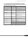
C.5
Parameters in the Server Management Information
( )The initial values have been unchanged.
I tem
I nitial value
E rror H alt Settings
BI O S s etting is
reflec ted
Boot O ptions
Setting
Sets the boot options .
( )C ontinue
( )H alt on errors
L as t P ower O n Reas on:
D is plays trigger for power- on.
L as t P ower O ff Reas on:
D is plays trigger for power- off.
P ower Res tore P olic y
Sets the operation at res toring power failure.
BI O S s etting is
reflec ted
( )A lways P ower off
( )A lways P ower on
( )Restore to powered state prior to power loss
A SR&R O ptions
A SR & R Boot D elay
A c tion with retry c ounter zero
BI O S s etting is
reflec ted
[ ]minutes
BI O S s etting is
( )P ower O ff
reflec ted
( )Boot D iagnos tic I D E D is k
( )Boot P XE
( )Boot iRM C Remote I mage
Retry c ounter
BI O S boot s ourc e for next boot
BI O S s etting is
reflec ted
[ ]
BI O S s etting is
( )Boot O ption
reflec ted
( )D iagnos tic Sys tem
BI O S rec overy flas h bit
D is abled
P ower C yc le D elay
BI O S s etting is
reflec ted
( )D is abled ( )E nabled
[ ]s ec onds
Watc hdog Settings
Software Watc hdog:
Boot Watc hdog:
BI O S s etting is
reflec ted for Boot
Sets Watc hdog
D is abled
( )E nabled
C ontinue
( )C ontinue ( )Res et ( )P ower C yc le
timeout delay: [ ]minutes
D is abled
( )E nabled
C ontinue
( )C ontinue ( )Res et ( )P ower C yc le
timeout delay: [ ]minutes
19
C Configuration Sheets of Remote Management Controller's Web Interface
C.6
Parameters in the Network Settings
( )The initial values have been unchanged.
I tem
Setting
I nitial value
E thernet
M A C A ddres s
Dis plays M A C addres s of iRM C .
I P A ddres s
BI O S s etting is
reflec ted
[
.
.
.
]
Subnet M as k
BI O S s etting is
reflec ted
[
.
.
.
]
Gateway
BI O S s etting is
reflec ted
[
.
.
.
]
DH C P
BI O S s etting is
reflec ted
( )E nabled
[ ]
[ ]
( )Dis abled
P orts and N etwork Servic es
H T T P P ort
80
H T T P S P ort
443
T elnet P ort
3172
SSH P ort
22
V N C P ort ~V ideo Sec ure P ort
[ ]
[ ]
For other ports , the s ettings are only
dis played (U nc hangeable).
T elnet Drop T ime
600
Forc e H T T P S
Dis abled
[ ]
( )E nabled
( )Dis abled
T elnet enabled
Dis abled
( )E nabled
( )Dis abled
Regis ter DH C P A ddres s in DN S
E nabled
( )E nabled
( )Dis abled
U s e iRM C N ame ins tead of
H os tname
E nabled
( )E nabled
( )Dis abled
DH C P C onfiguration
A dd Serial N umber
Dis abled
( )E nabled
( )Dis abled
A dd E xtens ion
Dis abled
( )E nabled
( )Dis abled
iRM C N ame
I RM C
[ ]
[ ]
E xtens ion
-iRM C
DN S Settings
20
DN S enabled
E nabled
( )E nabled
( )Dis abled
O btain DN S c onfiguration from
DH C P
E nabled
( )E nabled
( )Dis abled
DN S Domain
domain.c om
DN S Server1
0 .0 .0 .0
[ [
.
]
.
.
]
DN S Server2
0 .0 .0 .0
[
.
.
.
]
DN S Server3
0 .0 .0 .0
[
.
.
.
]
DN S Server4
0 .0 .0 .0
[
.
.
.
]
DN S Server5
0 .0 .0 .0
[
.
.
.
]
PRIMERGY TX200 S3 Configuration Sheets
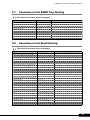
C.7
Parameters in the SNMP Trap Alerting
( )The initial values have been unchanged.
I tem
I nitial value
Setting
SN M P T rap D es tination
SN M P C ommunity
public
[
]
SN M P Server1
0 .0 .0 .0
[
]
SN M P Server2
0 .0 .0 .0
[
]
SN M P Server3
0 .0 .0 .0
[
]
SN M P Server4
0 .0 .0 .0
[
]
SN M P Server5
0 .0 .0 .0
[
]
SN M P Server6
0 .0 .0 .0
[
]
SN M P Server7
0 .0 .0 .0
[
]
C.8
Parameters in the Email Alerting
( )The initial values have been unchanged.
I tem
I nitial value
Setting
G lobal E mail P aging C onfiguration
E mail A lerting E nable
D is abled
( )E nabled
SM T P Retries
3
[
SM T P Retry D elay
30
[
]
SM T P Res pons e T imeout
30
[
]
]
P rimary SM T P Server C onfiguration
SM T P Server
0 .0 .0 .0
[
SM T P P ort
25
[
]
A uth T ype
N one
( )N one
]
A uth U s erN ame * 1
A uth P as s word * 1
* D is plays
C onfirm P as s word * 1
* D is plays
( )SM T P A U T H (RFC 2 5 5 4 )
[
]
Sec ondarySM T P ServerC onfiguration
SM T P Server
0 .0 .0 .0
[
SM T P P ort
25
[
]
A uth T ype
N one
( )N one
]
A uth U s erN ame * 1
A uth P as s word * 1
[
* D is plays
C onfirm P as s word * 1
* D is plays
( )SM T P A U T H (RFC 2 5 5 4 )
]
M ail Format dependend C onfiguration
From
M ailFrom@ domain.c om [
]
Subjec t
FixedM ailSubjec t
[
]
M es s age
FixedM ailM es s age
[
]
A dmin. N ame
I T S_U s erI nfo0
[
]
A dmin. P hone
I T S_U s erI nfo1
[
]
http://www.s erver.c om
[
RE M C S I d
Server U RL
U nc hangeable
]
* 1 :A ppears when " SM T P A U T H (RFC 2 5 5 4 )" is s elec ted for [A uth T ype].
21
C Configuration Sheets of Remote Management Controller's Web Interface
C.9
Parameters in the User Management
( )The initial values have been unchanged.
I tem
I nitial value
Setting
iRM C U s er I nformation
I D /N ame
2 admin
2 [
]
T he U s er N ame is dis played that is c reated by [N ew U s er]. C lic king "U s erN ame" dis plays a s etting
window for eac h U s erN ame.
T he default s ettings or the s ettings that are c onfigured when c reating a new us er are dis played on the
s etting window.
22
PRIMERGY TX200 S3 Configuration Sheets
User "nnnnnn(2)" Configuration
( )The initial values have been unchanged.
I tem
I nitial value
Setting
A c c es s I nformation
U s er E nabled
E nabled
( )D is abled
N ame
admin
[
( )E nabled
]
*D is plays
*E nter the pas s word again to c onfirm it.
P as s word
C onfirm P as s word
P rivilege / Shell
L A N P rivilege
O EM
( )U s er ( )O perator ( )A dminis trator
( )O E M
Remote M anager
( )SM A SH C L P ( )Remote M anager
( )I P M I Bas ic M ode ( )I P M I T erminal M ode
Serial P rivilege
U s er Shell
U ns upported
( )N one
E mail C onfiguration
E mail E nabled
D is abled
( )D is abled
M ail Format
Standard
( )Standard ( )Fixed Subjec t
( )I T S Format ( )Fujits u RE M C S- Format
( )E nabled
P refered M ail Server
A utomatic
( )A utomatic ( )P rimary ( )Sec ondary
U s er D es c ription
U s er0 2 D es c ription
{
E mail A ddres s
U s er0 2 @ domain.c om [
Fan Sens ors
WA RN I N G
}
]
( )N O N E ( )C RI T I C A L ( )WA RN I N G ( )A L L
T emperature Sens ors
WA RN I N G
( )N O N E ( )C RI T I C A L ( )WA RN I N G ( )A L L
C ritic al H ardware E rrors
A LL
( )N O N E ( )C RI T I C A L ( )WA RN I N G ( )A L L
Sys tem H ang
C RI T I C A L
( )N O N E ( )C RI T I C A L ( )WA RN I N G ( )A L L
P O ST E rrors
A LL
( )N O N E ( )C RI T I C A L ( )WA RN I N G ( )A L L
Sec urity
WA RN I N G
( )N O N E ( )C RI T I C A L ( )WA RN I N G ( )A L L
Sys tem Status
NO NE
( )N O N E ( )C RI T I C A L ( )WA RN I N G ( )A L L
D is k D rivers & C ontrollers
C RI T I C A L
( )N O N E ( )C RI T I C A L ( )WA RN I N G ( )A L L
N etwork I nterfac e
WA RN I N G
( )N O N E ( )C RI T I C A L ( )WA RN I N G ( )A L L
Remote M anagement
C RI T I C A L
( )N O N E ( )C RI T I C A L ( )WA RN I N G ( )A L L
Sys tem P ower
WA RN I N G
( )N O N E ( )C RI T I C A L ( )WA RN I N G ( )A L L
M emory
C RI T I C A L
( )N O N E ( )C RI T I C A L ( )WA RN I N G ( )A L L
O thers
NO NE
( )N O N E ( )C RI T I C A L ( )WA RN I N G ( )A L L
T his is the U s erN ame s etting window for us er I D 2 .
T he us er I D 2 ( admin ) is the U s erN ame/I D as initial value.
23
C Configuration Sheets of Remote Management Controller's Web Interface
User " ( )" Configuration
( )The user is not newly created.
I tem
Setting
I nitial value
A c c es s I nformation
U s er E nabled
Setting at c reating
a new us er
( )D is abled
N ame
Setting at c reating
a new us er
[
P as s word
Setting at c reating
a new us er
* D is plays
C onfirm P as s word
( )E nabled
]
* E nter the pas s word again to c onfirm it.
P rivilege / Shell
L A N P rivilege
Setting at c reating
a new us er
Serial P rivilege
U s er Shell
( )U s er ( )O perator ( )A dminis trator
( )O E M
U ns upported
Setting at c reating
( )SM A SH C L P ( )Remote M anager
a new us er
( )I P M I Bas ic M ode ( )I P M I T erminal M ode
( )N one
E mail C onfiguration
E mail E nabled
D is abled
( )D is abled
M ail Format
Standard
( )Standard ( )Fixed Subjec t
( )E nabled
P refered M ail Server
A utomatic
( )I T S Format ( )Fujits u RE M C S- Format
( )A utomatic ( )P rimary ( )Sec ondary
U s er D es c ription
{
E mail A ddres s
[
Fan Sens ors
WA RN I N G
}
]
( )N O N E ( )C RI T I C A L ( )WA RN I N G ( )A L L
T emperature Sens ors
WA RN I N G
( )N O N E ( )C RI T I C A L ( )WA RN I N G ( )A L L
C ritic al H ardware E rrors
A LL
( )N O N E ( )C RI T I C A L ( )WA RN I N G ( )A L L
Sys tem H ang
C RI T I C A L
( )N O N E ( )C RI T I C A L ( )WA RN I N G ( )A L L
P O ST E rrors
A LL
( )N O N E ( )C RI T I C A L ( )WA RN I N G ( )A L L
Sec urity
WA RN I N G
( )N O N E ( )C RI T I C A L ( )WA RN I N G ( )A L L
Sys tem Status
NO NE
( )N O N E ( )C RI T I C A L ( )WA RN I N G ( )A L L
D is k D rivers & C ontrollers
C RI T I C A L
( )N O N E ( )C RI T I C A L ( )WA RN I N G ( )A L L
N etwork I nterfac e
WA RN I N G
( )N O N E ( )C RI T I C A L ( )WA RN I N G ( )A L L
Remote M anagement
C RI T I C A L
( )N O N E ( )C RI T I C A L ( )WA RN I N G ( )A L L
Sys tem P ower
WA RN I N G
( )N O N E ( )C RI T I C A L ( )WA RN I N G ( )A L L
M emory
C RI T I C A L
( )N O N E ( )C RI T I C A L ( )WA RN I N G ( )A L L
O thers
NO NE
( )N O N E ( )C RI T I C A L ( )WA RN I N G ( )A L L
T his is the U s erN ame s etting window for us er I D 3 to 7 .
T he us er I D 3 to 7 have s ame s ettings as initial value. C opy this s heet when two or more us ers are
c reated.
24
PRIMERGY TX200 S3 Configuration Sheets
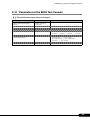
C.10 Parameters in the BIOS Text Console
( )The initial values have been unchanged.
I tem
BI O S C ons ole Redirec tion
O ptions
C ons ole Redirec tion E nabled
I nitial value
Setting
BI O S s etting is
reflec ted
( )D is abled ( )E nabled
C ons ole Redirec tion M ode
( )Standard
C ons ole Redirec tion P ort
( )Serial 1
( )E nhanc ed
Serial P ort Baudrate
( )1 2 0 0 ( )2 4 0 0 ( )4 8 0 0 ( )9 6 0 0
( )1 9 2 0 0 ( )3 8 4 0 0 ( )5 7 6 0 0 ( )1 1 5 2 0 0
( )Serial 2
Serial P ort Flow C ontrol
( )N one ( )XO N /XO FF ( )C T S/RT S
T erminal E mulation
( )V T 1 0 0 7 Bit
( )V T 1 0 0 8 Bit
( )P C - A N SI 7 Bit
( )P C - A N SI 8 Bit
( )V T 1 0 0 + ( )V T -U T F8
Serial 1 M ultiplexer
( )Sys tem
( )iRM C
25
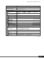
D Table of System Resource Management
D
Table of System Resource Management
The I/O port addresses that can be selected with various expansion cards are
described in the following table.
I/O Port Addresses
I/O port address (h)
Product name 100 140 180 1C 0 200 240 280 2C 0 300 340 380 3C 0 400
||||||||||||||||||||||||
Setup method
Serial port 1
||||||||||||||||||||||||
BIOS setup
Serial port 2
||||||||||||||||||||||||
BIOS setup
Parallel port 1
||||||||||||||||||||||||
BIOS setup
* indicate the I/O port address space that can be selected in the expansion card.
indicates that some or all of the 16 bytes that follow the marker address may be used
( space selected for default)
indicates that some or all of the 32 bytes that follow the marker address may be used
( space selected for default)
26
PRIMERGY TX200 S3 Configuration Sheets
E
Design Sheet of the RAID Configuration
Use this form to record the definitions of the disk groups (or the physical packs) and
the logical drives in the RAID configuration (array configuration).
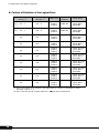
E.1
For PG-140FL (MegaRAID SAS 8300XLP)
Content of Definition of the Disk Group
Installation
HDD Slot / Bay
HDD model
name
HDD
capacity
Disk group / Spare disk *
(e.g.)
0
PG-HDB75A
73.4GB
(3)Disk group [0]
( )Spare disk
(e.g.)
1
PG-HDB75A
73.4GB
(3)Disk group [0]
( )Spare disk
0
( )Disk group [ ]
( )Spare disk
1
( )Disk group [ ]
( )Spare disk
2
( )Disk group [ ]
( )Spare disk
3
( )Disk group [ ]
( )Spare disk
4
( )Disk group [ ]
( )Spare disk
5
( )Disk group [ ]
( )Spare disk
*: When the hard disk is included in the disk group, put a checkmark to "Disk group"
and fill in the disk group number in [ ]. The disk group number is allocated in
order defining it like 0, 1, 2, …. When the hard disk is set as a spare disk, put a
checkmark to "Spare disk".
27
E Design Sheet of the RAID Configuration
Content of Definition of the Logical Drive
Logical drive number Disk group number
Logical drive
RAID level
(DG No.)*2
(LD No.)*1
capacity
Write policy
(e.g.)
LD : 0
DG : 0
( )RAID 0
(3)RAID 1
( )RAID 5
34464 MB
(3)Write Through
( )Write Back
( )Bad BBU
(e.g.)
LD : 1
DG : 0
( )RAID 0
(3)RAID 1
( )RAID 5
34464 MB
(3)Write Through
( )Write Back
( )Bad BBU
LD :
DG :
( )RAID 0
( )RAID 1
( )RAID 5
( )Write Through
( )Write Back
( )Bad BBU
LD :
DG :
( )RAID 0
( )RAID 1
( )RAID 5
( )Write Through
( )Write Back
( )Bad BBU
LD :
DG :
( )RAID 0
( )RAID 1
( )RAID 5
( )Write Through
( )Write Back
( )Bad BBU
LD :
DG :
( )RAID 0
( )RAID 1
( )RAID 5
( )Write Through
( )Write Back
( )Bad BBU
LD :
DG :
( )RAID 0
( )RAID 1
( )RAID 5
( )Write Through
( )Write Back
( )Bad BBU
LD :
DG :
( )RAID 0
( )RAID 1
( )RAID 5
( )Write Through
( )Write Back
( )Bad BBU
LD :
DG :
( )RAID 0
( )RAID 1
( )RAID 5
( )Write Through
( )Write Back
( )Bad BBU
LD :
DG :
( )RAID 0
( )RAID 1
( )RAID 5
( )Write Through
( )Write Back
( )Bad BBU
*1: Fill in the logical drive number. The logical drive number is allocated in order
defining it like 0, 1, 2, ….
*2: Fill in the disk group number defined in "■Disk group definitions".
28
PRIMERGY TX200 S3 Configuration Sheets
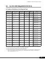
E.2
For PG-142E3 (MegaRAID SCSI 320-2)
Content of Definition of the Physical Pack
Installation
HDD Slot / Bay
HDD destination
SC SI channel
(C H)*1
HDD
destination
SC SI ID*2
HDD model
name
HDD
capacity
Physical pack
(Array)
/ Spare disk *3
(e.g.)
0
CH : 0
ID : 0
PG-HDB75A
73.4GB
(3)Physical pack [0]
( )Spare disk
(e.g.)
8
CH : 0
ID : 1
PG-HDB75A
73.4GB
(3)Physical pack [0]
( )Spare disk
0
CH :
ID :
( )Physical pack [ ]
( )Spare disk
1
CH :
ID :
( )Physical pack [ ]
( )Spare disk
2
CH :
ID :
( )Physical pack [ ]
( )Spare disk
3
CH :
ID :
( )Physical pack [ ]
( )Spare disk
4
CH :
ID :
( )Physical pack [ ]
( )Spare disk
5
CH :
ID :
( )Physical pack [ ]
( )Spare disk
6
CH :
ID :
( )Physical pack [ ]
( )Spare disk
7
CH :
ID :
( )Physical pack [ ]
( )Spare disk
8
CH :
ID :
( )Physical pack [ ]
( )Spare disk
9
CH :
ID :
( )Physical pack [ ]
( )Spare disk
10
CH :
ID :
( )Physical pack [ ]
( )Spare disk
11
CH :
ID :
( )Physical pack [ ]
( )Spare disk
12
CH :
ID :
( )Physical pack [ ]
( )Spare disk
13
CH :
ID :
( )Physical pack [ ]
( )Spare disk
When two or more array controllers are installed, copy this sheet for each array controller.
*1: Fill in the SC SI channel number of hard disk destination.
*2: Fill in the SC SI ID number of hard disk destination.
*3: When the hard disk is included in the physical pack, put a checkmark to "Physical pack"
and fill in the physical pack number in [ ]. The physical pack number is allocated in
order defining it like 0, 1, 2, ….
29
E Design Sheet of the RAID Configuration
Content of Definition of the Logical Drive
Logical drive number
(LD No.)*1
(e.g.)
(e.g.)
LD : 0
LD : 1
LD :
LD :
LD :
LD :
LD :
LD :
LD :
LD :
Physical pack number
(DG No.)*2
RAID level
Logical drive
capacity
Write policy
Array : 0
( )RAID
(3)RAID
( )RAID
( )RAID
0
1
34464 MB
5
10
(3)Write Through
( )Write Back
Array : 0
( )RAID
(3)RAID
( )RAID
( )RAID
0
1
34464 MB
5
10
(3)Write Through
( )Write Back
Array :
(
(
(
(
)RAID
)RAID
)RAID
)RAID
0
1
5
10
( )Write Through
( )Write Back
Array :
(
(
(
(
)RAID
)RAID
)RAID
)RAID
0
1
5
10
( )Write Through
( )Write Back
Array :
(
(
(
(
)RAID
)RAID
)RAID
)RAID
0
1
5
10
( )Write Through
( )Write Back
Array :
(
(
(
(
)RAID
)RAID
)RAID
)RAID
0
1
5
10
( )Write Through
( )Write Back
Array :
(
(
(
(
)RAID
)RAID
)RAID
)RAID
0
1
5
10
( )Write Through
( )Write Back
Array :
(
(
(
(
)RAID
)RAID
)RAID
)RAID
0
1
5
10
( )Write Through
( )Write Back
Array :
(
(
(
(
)RAID
)RAID
)RAID
)RAID
0
1
5
10
( )Write Through
( )Write Back
Array :
(
(
(
(
)RAID
)RAID
)RAID
)RAID
0
1
5
10
( )Write Through
( )Write Back
When two or more array controllers are installed, copy this sheet for each array controller.
*1: Fill in the logical drive number. The logical drive number is allocated in order defining
it like 0, 1, 2, ….
*2: Fill in the physical pack number defined in "■Physical pack definitions". When two or
more physical packs are used for RAID 10, fill in the range of physical pack number
like "0 - 2".
30
PRIMERGY TX200 S3 Configuration Sheets
E.3
For Integrated Mirroring SAS
Content of Definition of the Logical Drive
Installation
HDD Slot / Bay
HDD model name
HDD capacity
Logical drive capacity
(e.g.)
0
PG-HDB75A
73.4GB
34464MB
(e.g.)
1
PG-HDB75A
73.4GB
34464MB
0
1
31
F Design Sheet
F
Design Sheet
When setting up the server using ServerStart, select the setting values and put a
check mark in parentheses below in advance to ensure setup is performed smoothly.
F.1
RAID/Disk Wizard
Parameters
Setting
( ) Logical Drive View
( ) Mass Storage C ontroller View
(The RAID configuration can be specified)
( ) RAID
( ) SC SI
( ) Fibrechannel ( ) IDE
C ontroller
When you select "RAID" with controller's type
C onfigure RAID
( ) Automatically
( ) Manually
Existing RAID Array
( ) Delete Existing RAID Array
C ontroller Vendor
C ontroller Number
C onfigure R AID:
Ma nually
RAID Level
Number of Disks
HotSpare
( ) Yes
( ) No
Disk ↓Make copies when installing multiple disks.
Partition ↓Make copies when more sheets are needed.
Volume label
32
File system
( ) NTFS ( ) FAT
Partition size
( ) Auto setting
( ) MB
Quick format
( ) Execute
( ) Do not execute
Partition Usage
( ) Boot
( ) OS ( ) Data
PRIMERGY TX200 S3 Configuration Sheets
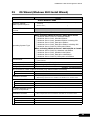
F.2
OS Wizard (Windows 2003 Install Wizard)
Parameters
Regional settings
(with keyboard layout)
Setting
Install Windows 2003
( ) U s e the default regional s ettings for the Windows -V ers ion you are
ins talling
( ) Selec t here ( )
Password for Administrator
account
Computer Identification
Operating System Type
When selecting Windows Server 2003/R2 to install
( ) Windows Server 2003 R2, Standard Edition
( ) Windows Server 2003, Standard Edition
( ) Windows Server 2003, Standard Edition including SP1
( ) Windows Server 2003, Enterprise Edition
( ) Windows Server 2003, Enterprise Edition including SP1
( ) Windows Server 2003 R2, Enterprise Edition
When selecting Windows Server 2003 x64/R2 to install
( ) Windows Server 2003 R2, Standard x64 Edition
( ) Windows Server 2003, Standard x64 Edition
( ) Windows Server 2003, Enterprise x64 Edition
( ) Windows Server 2003 R2, Enterprise x64 Edition
License Mode
( ) per Seat
( ) per Server
User permitted
(Only when concurrent users are selected)
will participate in
( ) a work group
( ) a domain
Workgroup or Domain Name
(Default - MYUSERGROUP)
User account to create computer account (only when Domain is selected)
User account
Password
Installation method
( ) O perating s ys tem s ourc e media in A vailable in loc al C D-RO M drive
( ) O perating s ys tem s ourc e media in A vailable on a remote s hare
when installing OS from remote share
Remote Source Path
Remote Username
Remote Password
( ) Install Windows Server 2003 R2 Components
To install Windows Server
2003 R2 Components
Installation method
( ) R2 C omponents s ourc e media is available in loc al C D-RO M drive
( ) R2 C omponents s ourc e media is available on a remote s hare
When you install it from a remote share
Remote Source
Remote Username
Remote Password
(continued)
33
F Design Sheet
Parameters
Setting
Installation Directory and Time zone
(Default -(GMT+01:00) Amsterdam, Berlin,
Time Zone
Bern, Rome, Stockholm, Vienna)
Installation Drive
( ) Use default
( ) Drive Letter
( ) C : ( ) D: ( ) E: ( ) F: ( ) G: ( ) H: ( ) I: ( ) J:
When selecting drive name ( ) K: ( ) L: ( ) M: ( ) N: ( ) O: ( ) P: ( ) Q: ( ) R:
( ) S: ( ) T: ( ) U: ( ) V: ( ) W: ( ) X: ( ) Y: ( ) Z:
Installation Directory
Installation destination
( ) Use default
( ) Specify in advance
(Default - \winnt)
User Name
User Name
Organization
C omputer Name
Product-ID
( )
-
-
-
-
Display settings
Resolution
Vrefresh
BitsPerPel
Installation method
( ) 640 * 480
( ) 1156 * 864
( ) 800 * 600 ( ) 1024 * 768
( ) 1280 * 1024 ( ) 1600 * 1200
( ) 60 ( ) 70 ( ) 72 ( ) 75 ( ) 80 ( ) 85 ( ) 100
( ) 16 colors ( ) 256 colors
( ) High C olor (16bits)
( ) True C olor (24bits) ( ) True C olor (32bits)
Network protocol
( ) Install Unattended
( ) Install Manually
Network protocol property (for auto-installation)
C onnection name
Available Protocols
( ) TC P/IP
( ) DLC
( ) NWIPX
( ) NetMon
Use of DHC P
(When TC P/IP selected)
( ) Use DHC P
( ) NetBEUI
( ) PPTP
( ) Apple Talk
Adapter 1
Do not use DHCP
IP-Address
Subnet Mask
Default Gateway
Subnet mas k (additional)
(only when added)
(only when added)
D efault gateway
(additional)
(only when added)
I P addres s (additional)
DNS domain name
DNS server address
Use WINS
WINS server address
NetBIOS Option
(only when specified)
(only when specified)
( ) Use
DHC P (only when selected to use)
( ) Use NetBIOS setting from the DHC P Server
( ) Use NetBIOS over TC P/IP
( ) Do not use NetBIOS over TC P/IP
Only when NWIPX is selected
0x
Network number
0x
Frame type
Copy this sheet to install multiple adapters.
I nternal network number
(continued)
34
PRIMERGY TX200 S3 Configuration Sheets
Parameters
Setting
(Continuation of Network protocol)
C onnection name
Protocol binding to this
adapter
( ) TC P/IP
( ) DLC
Use of DHC P
(When TC P/IP selected)
( ) Use DHC P
( ) NWIPX
( ) NetMon
( ) NetBEUI
( ) PPTP
( ) Apple Talk
Adapter 2
Do not use DHCP
IP Address
Subnet Mask
Default Gateway
Subnet mas k (additional)
(only when added)
(only when added)
D efault gateway
(additional)
(only when added)
I P addres s (additional)
DNS domain name
DNS server address
Use WINS
WINS server address
NetBIOS Option
(only when specified)
(only when specified)
( ) Use
DHC P(only when selected to use)
( ) Use NetBIOS setting from the DHC P Server
( ) Use NetBIOS over TC P/IP
( ) Do not use NetBIOS over TC P/IP
Only when NWIPX is selected
0x
Network number
0x
Frame type
Copy this sheet to install multiple adapters.
I nternal network number
(continued)
35
F Design Sheet
Parameters
Select installation method
Setting
Software Components
( ) Install default C omponents
( ) Install customized C omponents
R2
( ) R2 C omponents
Only when selecting R2 components to install
Active Directory
(
(
(
(
(
)
)
)
)
)
Distributed File System
( ) DFS Management
( ) DFS Replication Service
File Server
( ) Management C onsole
Microsoft Services for NFS
(
(
(
(
(
(
(
Unix Identity Management
( ) Administration C omponents
( ) Password Synchronisation
( ) Server For NIS
)
)
)
)
)
)
)
Application Mode(ADAM)
C laims-Aware Applications
Traditional Applications
Federation Service
Federation Service Proxy
User Name Mapping
Microsoft Services for NFS Administration
C lient for NFS
Server for NFS
RPC Portmapper
RPC External Data Representation
Server For NFS Authentication
Windows SharePoint Services Enable Windows Sharepoint Services
( ) C ommon Log File System
( ) Microsoft .NET Framework2.0(English)
( ) Microsoft .NET Framework2.0(International)
( ) Microsoft .NET Framework2.0 Languagepack
Additional C omponents
( ) Print Management C onsole
( ) Storage Manager SAN
( ) Storage Ressource Manager
( ) Windows Subsystem for UNIX based Applications
Uninstall C omponennts
(
(
(
(
)
)
)
)
uninstall
uninstall
uninstall
uninstall
hidden C FSC ommonUIFX
hidden DFSExt
hidden DFSRHelper
set of files from FileServerManagement C onsole
(continued)
36
PRIMERGY TX200 S3 Configuration Sheets
Parameters
Setting
(Continuation of Software Components)
Only when selecting component to install
Application and utilities
Accessories
(
(
(
(
(
(
(
(
)
)
)
)
)
)
)
)
clipboard viewer
Desktop Wallpaper
Document Template
Paint
All available mousepointers
Word pad
C alculator
C haracter Map
Accessibility Wizard
( ) Install
C ommunications
( ) C hat
( ) Hyper Terminal
Application server
ASP.NET web
development platform
( ) Install
Application server
console
( ) Install
(
(
(
(
(
Internet information
services
(IIS)
)
)
)
)
)
( )
( )
( )
( )
(
(
(
(
Te rm inal Se rvice s lice nsing (
Remote install Services
(
ne twork C O M + a cce ss
DTC network access
Indexing Server Files
Terminal Services
)
)
)
)
)
)
FrontPage 2002 Server Extensions
FTP (File Transfer Protocol) service
NNTP Service - NNTP Service
SMTP Service - SMTP Service
World Wide Web Server
- Internet Information Services ASP support
World Wide Web Server
- Internet Information Services web DAV publishing
World Wide Web Server
- World Wide Web (WWW) Service
World Wide Web Server
- Internet Information Services internet data connector
World Wide Web Server
- Internet Information Services web user interface
Install
Install
Install
Install
Install
Install
C ertificate Service
( ) Insta ll ( ) Se rve r com pone nts of the C e rtificate Se rvice s
( ) W e b clie nt com pone nt of the C e rtificate Se rvice s
POP3 root component
( ) Install ( ) POP3 main service
( ) POP3 web user interface
(continued)
37
F Design Sheet
Parameters
Setting
FTP service property (Only when FTP service is selected)
FTP site directory
(Default - \Inetpub\Ftproot)
WWW service property (Only when WWW service is selected)
WWW server directory
(Default - \Inetsrv\WWWroot)
Terminal server property (Only when terminal server is selected)
Terminal service
( ) Permit remote desktop during unattended setup
Authorize the following acce ss
( ) Access permit compatible with Windows 2000 Users
pe rm its to te rm ina l se rvice
( ) Access permit compatible with Terminal Server 4.0 Users
use rs
License mode
( ) Number of simultaneous users
( ) Number of connected sessions
C urrent mode for terminal
service
( ) Application server mode
( ) Remote management mode
Services
( ) Services for Macintosh (SFM)
Other network File and Print
( ) Print Service for Macintosh
Services
( ) Print Service for UNIX
Networking Services
(
(
(
(
(
)
)
)
)
)
WINS Server
Internet Authentication Service (IAS)
MS DNS Server
Simple TC P/IP Service
MS DHC P Serve
Management and Monitoring ( ) Network Monitor tools
Tools
( ) SNMP Service (Required to install SNMP-ServerView)
SNMP details (Only when SNMP is selected)
Trap
C ommunity name
Trap destination
Security
Send authentication trap ( ) Send
Receivable community
name
Receive SNMP packet
from all hosts
Host name
Agent
C ontact
Address
Service
( ) Receive
(only when specified)
( ) Physical
( ) End-to-End
( ) Datalink and sub network
( ) Application
( ) Internet
(continued)
38
PRIMERGY TX200 S3 Configuration Sheets
Parameters
Setting
Active Directory details setting (only when DNS is selected)
Install Active Directory
( ) Install
Active Directory type
(
(
(
(
)
)
)
)
C reate a domain in a new forest
Additional domain controller of the existing domain
C reate a new child domain under the existing domain tree
C reate a new domain tree in the existing forest
Database folder
Log folder
SYSVOL folder location
C ompatibility with
( ) Permit
Windows 2000 or earlier
C reate a domain in a new forest (only when selected)
C omplete DNS name of
the new domain
Domain NetBIOS name
Additional domain controller of the existing domain (only when selected)
User name
Password
Domain
C omplete DNS name of
the existing domain
C reate a new child domain under the existing domain tree (only when selected)
User name
Password
Domain
C omplete DNS name of
the parent domain
New child domain name
Domain NetBIOS name
C reate a new domain tree in the existing forest (only when selected)
User name
Password
Domain name
C omplete DNS name of
the new domain
Domain NetBIOS name
39
F Design Sheet
F.3
OS Wizard (Windows 2000 Install Wizard)
Parameters
Regional settings
(with keyboard layout)
Setting
Install Windows 2000
( ) U s e the de fault re gional s e ttings for the Windows - V e rs ion y ou are
ins talling
( ) S e le c t he re ( )
Password for Administrator
Computer identification
Operating System Type
(
(
(
(
)
)
)
)
Windows
Windows
Windows
Windows
2000
2000
2000
2000
License mode
( ) per Seat
( ) per Server
Server
Server including SP4
Advanced Server
Advanced Server including SP4
User Permitted
(Only when concurrent users are selected)
Participation
( ) a work group
( ) a domain
Work group or domain name
(Default - MYUSERGROUP)
User account to create computer account (only when Domain is selected)
User account
Password
Installation method
( ) O pe rating s y s te m s ourc e me dia in A v ailable in loc al C D - R O M driv e
( ) O pe rating s y s te m s ourc e me dia in A v ailable on a re mote s hare
when installing OS from remote share
Remote source
Remote Username
Reote Password
Time zone and installation driv e
(Default -(GMT+01:00)
Select time zone
Bern, Rome,
Installation drive
( ) Use default
( ) Drive name
( ) C : ( ) D: ( ) E: ( ) F: ( ) G: ( ) H: (
( ) K: ( ) L: ( ) M: ( ) N: ( ) O: ( ) P: (
When selecting drive name
( ) S: ( ) T: ( ) U: ( ) V: ( ) W: ( ) X: (
Installation directory
Amsterdam, Berlin,
Stockholm, Vienna)
) I: ( ) J:
) Q: ( ) R:
) Y: ( ) Z:
( ) Use default
( ) Specify during installation
( ) Specify in advance
Installation destination
(Default - \winnt)
User information
Name
C ompany name
C omputer name
Product-ID
Display setting
-
Resolution
( ) 640 * 480
( ) 1156 * 864
Vrefresh
( ) 60 ( ) 70 ( ) 72 ( ) 75 ( ) 80 ( ) 85 ( ) 100
BitsPerPel
40
( )
( ) 800 * 600 ( ) 1024 * 768
( ) 1280 * 1024 ( ) 1600 * 1200
( ) 16 colors ( ) 256 colors ( ) High C olor (16bits)
( ) True C olor (24bits) ( ) True C olor (32bits)
(continued)
PRIMERGY TX200 S3 Configuration Sheets
Parameters
Setting
Network protocol
( ) Auto-installation
( ) Install driver only
Network protocol property (when auto-installation is selected)
C onnection name
Protocol binding to this
( ) TC P/IP ( ) NWIPX ( ) NetBEUI
adapter
( ) DLC
( ) NetMon ( ) PPTP
Installation method
Use of DHC P
(When TC P/IP selected)
Adapter 1
Do not use DHCP
IP-Address
Subnet Mask
Default Gateway
IP address
(additional)
Subnet mask
(additional)
Default gateway
(additional)
DNS domain name
DNS server address
Use WINS
WINS server address
NetBIOS Option
( ) Apple Talk
( ) Use
(only when added)
(only when added)
(only when added)
(only when specified)
(only when specified)
( ) Use
(only when selected to use WINS)
( ) Use NetBIOS setting from the DHC P Server
( ) Enable NetBIOS over TC P/IP
( ) Disable NetBIOS over TC P/IP
Only when NWIPX is selected
Internal network
number
0x
Network number
0x
( ) Ethernet Ⅱ ( ) Ethernet 802.2 ( ) Ethernet 802.3
Frame type
( ) Ethernet SNAP ( ) Auto-detection
Copy this sheet to install multiple adapters.
(continued)
41
F Design Sheet
Parameters
Setting
(Continuation of Network protocol)
C onnection name
Protocol binding to this
adapter
( ) TC P/IP
( ) DLC
Use of DHC P
(When TC P/IP selected)
( ) Use
( ) NWIPX
( ) NetMon
( ) NetBEUI
( ) PPTP
( ) Apple Talk
IP Address
Subnet Mask
Default Gateway
Adapter 2
Do not use DHCP
IP address
(additional)
(only when added)
Subnet mask
(additional)
(only when added)
Default gateway
(additional)
(only when added)
DNS domain name
DNS server address
Use WINS
WINS server address
NetBIOS Option
(only when specified)
(only when specified)
( ) Use
(only when selected to use WINS)
( ) Use NetBIOS setting from the DHC P Server
( ) Enable NetBIOS over TC P/IP
( ) Disable NetBIOS over TC P/IP
Only when NWIPX is selected
Internal network
number
Network number
0x
0x
( ) Ethernet Ⅱ ( ) Ethernet 802.2 ( ) Ethernet 802.3
Frame type
( ) Ethernet SNAP ( ) Auto-detection
Copy this sheet to install multiple adapters.
(continued)
42
PRIMERGY TX200 S3 Configuration Sheets
Parameters
Setting
Software Components
Select installation method
( ) Select component to install
Only when selecting component to install
Service
FTP site directory
WWW Server directory
C ommunication
(
(
(
(
(
(
(
(
(
(
(
(
)
)
)
)
)
)
)
)
)
)
)
)
(IIS) common component
(IIS) online help
FTP (File Transfer Protocol) server
Internet service manager (HTML)
Internet information service snap-in
NNTP Service
SMTP Service
WWW (World Wide Web) server
Remote install service
Remote storage
Terminal service
Terminal service license
(Default - \Inetpub\Ftproot)
(Default - \Inetsrv\WWWroot)
Setting
Multimedia
( ) C D player
( ) Utopia sound setting
( ) Volume control
Accessory
(
(
(
(
(
Game
Service
)
)
)
)
)
( ) Media player
( ) Sound recorder
( ) Sample sound
Accessibility setting wizard ( ) C haracter code table
C alculator
( ) Paint
Word pad
( ) Document templates
Script debugger
( ) Object packager
Desktop wallpaper
( ) Free cell ( ) Mine sweeper ( ) Pinball ( ) Solitaire
Service
(
(
(
(
(
(
(
(
(
(
(
(
)
)
)
)
)
)
)
)
)
)
)
)
Simple Network Management Protocol (SNMP)
Domain Name System (DNS)
Dynamic Host C onfiguration Protocol (DHC P)
Windows Internet Name Service (WINS)
Simple TC P/IP service
Network monitor tool
Internet authentication service
Site Server ILS service
Print service for UNIX
Print service for Macintosh
C onnection manager component
File service for Macintosh
(continued)
43
F Design Sheet
Parameters
Setting
SNMP details (only when SNMP is selected)
Trap
C ommunity name
Trap destination
Security
Send authentication trap
( ) Send
Receivable community
name
Receive SNMP packet
from all hosts
Host name
Agent
C ontact
Address
Service
( ) Receive
(only when specified)
( ) Physical
( ) Datalink and sub network
( ) Internet
( ) End-to-End ( ) Application
(continued)
44
PRIMERGY TX200 S3 Configuration Sheets
Parameters
Setting
Active Directory details setting (only when DNS is selected)
Install Active Directory
( ) Install
( ) C reate a new forest of a domain tree
( ) Add additional domain controller of the existing domain
Active Directory type
( ) Add a new child domain under the existing domain tree
( ) Place a new domain tree in the existing forest
Database location
Log location
SYSVOL folder location
Acce ss pe rm it
com pa tibility with W indows ( ) Permit
2000 or e a rlie r se rve r
C reate a new forest of a domain tree (only when selected)
C omplete DNS name of
the new tree
Domain NetBIOS name
Add additional domain controller of the existing domain (only when selected)
User name
Password
Domain
C omplete DNS name of
the domain
Add a new child domain under the existing domain tree (only when selected)
User name
Password
Domain
Parent domain name
C hild domain name
Domain NetBIOS name
Place a new domain tree in the existing forest (only when selected)
User name
Password
Domain name
C omplete DNS name of
the new tree
Domain NetBIOS name
45
F Design Sheet
F.4
Application Wizard
Parameters
Installable applications
Setting
(
(
(
(
(
)
)
)
)
)
Windows 2000 service pack4
Windows Server 2003 service pack1
ServerView
DSNAP
RAID Management Tool
Userspecific Command
Userspecific Command
When installing from remote server
Remote Source Path
Remote Username
Remote Password
46
(only when selecting additional software)
( ) Install selected application from Local CD
( ) Install selected application from Remote Server
( ) Install
( ) Do not install
PRIMERGY TX200 S3 Configuration Sheets
G
Accident Sheet
Name (Product ID)
PRIMERGY TX200 S3 (PG
)
OS
Environment
LAN/WAN config.
DATE/TIME
Phase of accident
What did you do?, what message? etc.
Attached paper
Yes / No
47
PRIMERGY TX200 S3
Configuration Sheets
B7FH-4441-01ENZ0-01
Issued on
Issued by
September, 2006
FUJITSU LIMITED
● The contents of this manual may be revised without prior notice.
● Fujitsu assumes no liability for damages to third party copyrights or other rights
arising from the use of any information in this manual.
● No part of this manual may be reproduced in any form without the prior written
permission of Fujitsu.